

See other KIA Soul:


Fuse Layout Kia Soul 2020-…
Contents

Cigar lighter (power outlet) fuses in the Kia Soul are located in the Instrument panel fuse box (see fuse “POWER OUTLET” (Front Left Power Outlet)), and in the Engine compartment fuse box (fuses “POWER OUTLET 1” (Power Outlet Relay), “POWER OUTLET 2” (Front Right Power Outlet) and “POWER OUTLET 3” (Rear Power Outlet)).
Table of Contents
Instrument panel fuse box
Instrument panel fuse box
Fuse box location
The fuse box is located behind the cover on the driver’s side of the instrument panel.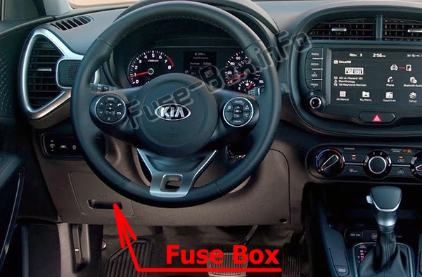
Fuse box diagram
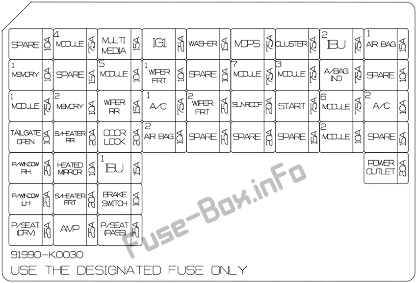
Assignment of the fuses in the Instrument panel (2020)
| Name | Amp rating | Protected component |
|---|---|---|
| POWER OUTLET | 20 A | Front Power Outlet LH |
| MODULE2 | 10 A | Sound Mood Lamp, E/R Junction Block (Power Outlet Relay), Audio, DC-DC Converter, Front/Rear USB Charger, Wireless Charger, AMP, Driver/Passenger Door Mood Range Lamp, Power Outside Mirror Switch, A/V & Navigation Head Unit, IBU |
| HEATED MIRROR | 10 A | Driver/Passenger Power Outside Mirror, A/C Control Module, ECM |
| IG1 | 25 A | PCB Block (Fuse – ABS3, ECU5, SEN50R4, TCU2) |
| AIR BAG1 | 15 A | Occupant Detection Sensor, SRS Control Module |
| A/BAG IND | 7.5 A | Instrument Cluster, A/C Control Module |
| IBU2 | 7.5 A | IBU |
| CLUSTER | 7.5 A | HUD, Instrument Cluster |
| MDPS | 7.5 A | MDPS Unit |
| MODULE3 | 7.5 A | ATM Shift Lever, Stop Lamp Switch |
| M0DULE4 | 7.5 A | Multifunction Camera, IBU, Smart Cruise Control Radar, Crash Pad Switch, Blind-Spot Collision Warning Unit LH/RH |
| MODULE5 | 10 A | Front Air Ventilation Seat Control Module, A/C Control Module, A/V & Navigation Head Unit, Front Seat Warmer Control Module, ATM Shift Lever Indicator, Rear Seat Warmer Module, Audio |
| A/C1 | 7.5 A | E/R Junction Block (Blower Relay, PTC Heater #l/#2 Relay), A/C Control Module |
| WIPER FRT2 | 25 A | Front Wiper Motor, PCB Block (Front Wiper (Low) Relay) |
| WIPER RR | 15 A | Rear Wiper Motor, ICM Relay Box (Rear Wiper Relay) |
| WASHER | 15 A | Multifunction Switch |
| MODULE6 | 7.5 A | IBU |
| MODULE7 | 7.5 A | Front/Rear Seat Warmer Control Module, Front Air Ventilation Seat Control Module, Front Heated Box (Front Heated LH Relay) |
| WIPER FRT1 | 10 A | Front Wiper Motor, PCB Block (Front Wiper (Low) Relay), IBU, ECM/PCM |
| A/C2 | 10 A | ECM/PCM, A/C Control Module, Blower Resistor, Blower Motor, E/R Junction Block (Blower Relay) |
| START | 7.5 A | W/O Smart Key & IMMO.: ICM Relay Box (Burglar Alarm Relay) With Smart Key or IMMO.: Transmission Range Switch, IBU,ECM/PCM, E/R Junction Block (Start Relay) |
| P/WINDOW LH | 25 A | Power Window LFI Relay, Driver Safety Power Window Module |
| P/WINDOW RH | 25 A | Power Window RH Relay, Passenger Safety Power Window Module |
| TAILGATE OPEN | 10 A | Tail Gate Open Relay |
| SUNROOF | 20 A | Sunroof Motor |
| AMP | 25 A | W/O ISG: AMP With ISG: DC-DC Converter |
| S/HEATER FRT | 20 A | Front Seat Warmer Control Module, Front Air Ventilation Seat Control Module |
| P/SEAT (DRV) | 25 A | Driver Seat Manual Switch |
| P/5EAT (PASS) | 25 A | Passenger Seat Manual Switch |
| S/HEATER RR | 20 A | Rear Seat Warmer Control Module |
| DOOR LOCK | 20 A | Door Lock/Unlock Relay, ICM Relay Box (T/Turn Unlock Relay) |
| BRAKE SWITCH | 10 A | Stop Lamp Switch, IBU |
| IBU1 | 15 A | IBU |
| AIR BAG2 | 10 A | SRS Control Module |
| MODULE 1 | 7.5 A | Hazard Switch, Key Interlock Solenoid, Rain Sensor, Data Link Connector |
| MEMORY 1 | 10 A | Instrument Cluster, A/C Control Module, HUD |
| MULTI MEDIA | 15 A | Audio, A/V & Navigation Head Unit, DC-DC Converter |
Engine compartment fuse box
Engine compartment fuse box
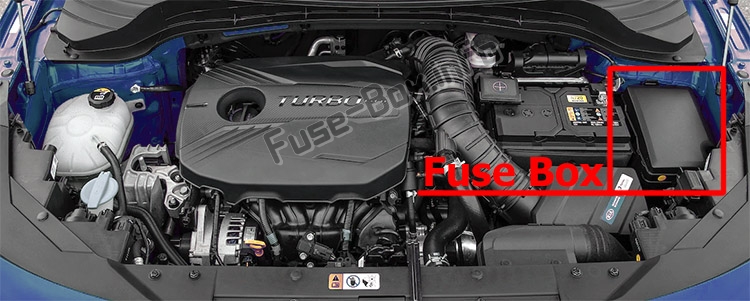
Fuse box location
Fuse box diagram
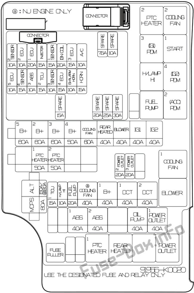
Assignment of the fuses in the engine compartment (2020)
| Name | Amp rating | Circuit Protected |
|---|---|---|
| ALT | 150 A (G4FJ) 180 A (G4NH) |
Alternator, E/R Junction Block (Fuse – MDPS (Motor Driven Power Steering), ESC (Electronic Stability Control) 1, ESC (Electronic Stability Control)2) |
| MDPS | 80 A | MDPS (Motor Driven Power Steering) Unit |
| B+5 | 60 A | PCB (Printed Circuit Board) Block (Engine Control Relay, Fuse – ECU3, ECU4, HORN, A/C) |
| B+2 | 60 A | ICU Junction Block (IPS (1CH), IPS Control Module) |
| B+3 | 60 A | ICU Junction Block (IPS Control Module) |
| B+4 | 50 A | ICU Junction Block (Fuse – P/WINDOW LH, P/WINDOW RH, TAILGATE OPEN, SUNROOF, AMP, S/HEATER FRT, P/SEAT (DRV), P/SEAT (PASS) |
| COOLING FAN | 60 A | G4FH: Cooling Fan #1 Relay |
| REAR HEATER | 40 A | Rear Heater Relay |
| BLOWER | 40 A | Blower Relay |
| IG1 | 40 A | W/O Smart Key: Ignition Switch With Smart Key: E/R Junction Block (PDM (ACC) #2 Relay, PDM (IG1) #3 Relay) |
| IG2 | 40 A | W/O Smart Key: Ignition Switch, Start #1 Relay With Smart Key: E/R Junction Block (PDM (IG2) #4 Relay), Start #1 Relay |
| PTC HEATER 1 | 50 A | PTC Heater #1 Relay |
| PTC HEATER 2 | 50 A | PTC Heater #2 Relay |
| ABS1 | 40 A | ESC (Electronic Stability Control) Module, ABS (Anti-lock Brake System) Control Module, Multipurpose Check Connector |
| ABS2 | 40 A | ESC (Electronic Stability Control) Module, ABS (Anti-lock Brake System) Control Module |
| POWER OUTLET 1 | 40 A | Power Outlet Relay |
| POWER OUTLET 2 | 20 A | Front Power Outlet RH |
| POWER OUTLET 3 | 20 A | Rear Power Outlet |
| OIL PUMP | 40 A | Electronic Oil Pump |
| VACUUM PUMP | 20 A | Electric Vacuum Pump |
| TCU1 | 15 A | TCM (Transmission Control Module) |
| H/LAMP HI | 10 A | Head Lamp (High) Relay |
| FUEL PUMP | 20 A | Fuel Pump Relay |
| COOLING FAN | 40 A | G4NH: Cooling Fan #1/#2 Relay |
| B+1 | 40 A | ICU Junction Block (Long Term Load Latch Relay, Fuse -BRAKE SWITCH, MODULE 1, IBU1, AIR BAG2, DOOR LOCK, S/HEATER RR) |
| DCT1 | 40 A | TCM (Transmission Control Module) |
| DCT2 | 40 A | TCM (Transmission Control Module) |
| ECU3 | 15 A | GAMMA 1.6L T-GDI: ECM (Engine Control Module) NU 2.0L MPI: PCM (Power train Control Module) |
| ECU4 | 15 A | GAMMA 1.6L T-GDI: ECM (Engine Control Module) NU 2.0L MPI: PCM (Power train Control Module) |
| HORN | 15 A | Horn Relay |
| A/C | 10 A | A/C COMP Relay |
| IGN COIL | 20 A | Ignition Coil #1/#2/#3/#4 |
| SENSOR3 | 10 A | E/R Junction Block (Fuel Pump Relay) |
| INJECTOR | 15 A | NU 2.0L MPI: Injector #1 /#2/#3/#4 |
| ECU2 | 10 A | GAMMA 1,6L T-GDI: ECM (Engine Control Module) |
| SENSOR1 | 15 A | Oxygen Sensor (Up/Down) |
| SENSOR2 | 10 A | A/C COMP Relay, Canister Close Valve, GAMMA 1.6L T-GDI: Oil Control Valve #1 /#2, Purge Control Solenoid Valve, E/R Junction Block (Cooling Fan #1 Relay), Turbo Recirculation Valve NU 2.0L MPI: PCM (Power train Control Module) |
| ABS3 | 10 A | ESC (Electronic Stability Control) Module, ABS (Anti-lock Brake System) Control Module, Data Link Connector, Multipurpose Check Connector |
| ECU5 | 10 A | GAMMA 1.6L T-GDI: ECM (Engine Control Module) NU 2.0L MPI: PCM (Power train Control Module) |
| SENSOR4 | 15 A | GAMMA 1.6L T-GDI: Electric Vacuum Pump NU 2.0L MPI: Electronic Oil Pump |
| TCU2 | 15 A | GAMMA 1.6L T-GDI: TCM (Transmission Control Module), Transmission Range Switch NU 2.0L MPI: Transmission Range Switch |


