See other KIA Forte / Cerato:


Table of Contents
Fuse Layout KIA Forte / Cerato 2019-…
Contents

Cigar lighter (power outlet) fuse in the KIA Forte / Cerato is located in the Instrument panel fuse box (see fuse “POWER OUTLET” – Cigarette Lighter), and in the Engine compartment fuse box (fuses “POWER OUTLET 2” – Front Power Outlet, “POWER OUTLET 1” – Power Outlet Relay).
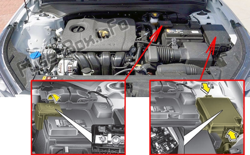
Fuse box location
Fuse box location
Instrument panel
The fuse panel is located in the driver’s side of the instrument panel behind the cover.
Engine compartment
Fuse box diagrams
Fuse box diagrams
2019
Instrument panel
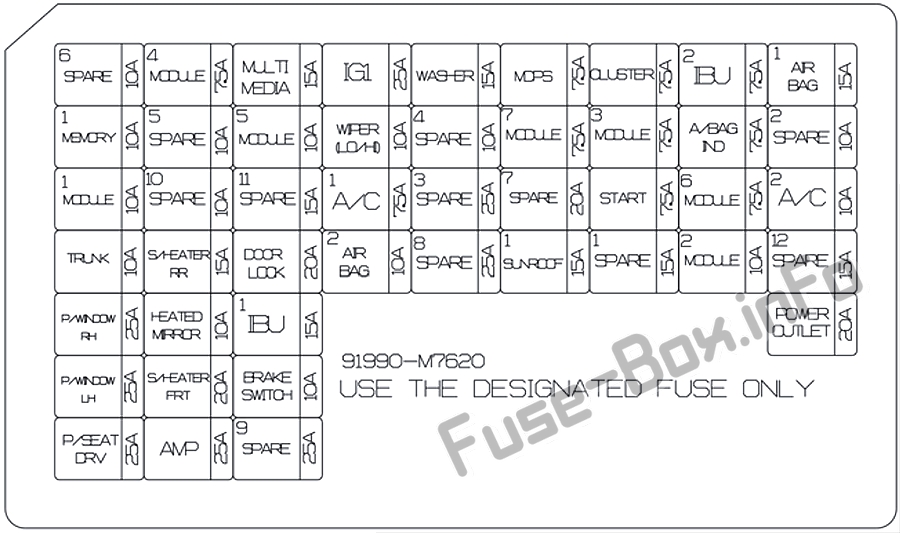
Assignment of the fuses in the Instrument panel (2019)
| Name | Amp rating | Circuit Protected |
|---|---|---|
| MEMORY 1 | 10A | Driver IMS (Integrated memory system) Module,Air Conditioner Control Module, Instrument Cluster |
| MODULE 1 | 10A | Key Interlock Switch, Data Link Connector, Hazard Switch, Driver/Passenger Smart Key Outside Handle, ICM (Integrated Circuit Module) Relay Box (Outside Mirror Folding/Unfolding Relay) |
| TRUNK | 10A | Trunk Relay |
| POWER WINDOW RH | 25A | Power Window Right Handle side Relay |
| POWER WINDOW LH | 25A | Power Window Left Handle side Relay, Driver Safety Power Window Module |
| POWER SEAT DRIVER | 25A | Driver Seat Manual Switch |
| MODULE 4 | 7.5A | Lane Keeping Assist Unit, IBU (Integrated Body Control Unit), Forward Collision Avoidance Assist Unit, Blind-Spot Collision Warning Unit Left Handle side/Right Handle side |
| SEAT HEATER REAR | 15A | Rear Seat Warmer Control Module |
| HEATED MIRROR | 10A | Driver/Passenger Power Outside Mirror, Air Conditioner Control Module, ECM (Engine Control Module)/PCM (Power train Control Module) |
| SEAT HEATER FRONT | 20A | Front Seat Warmer Control Module, Front Air Ventilation Seat Control Module |
| AMP | 25A | AMP (Amplifier) |
| MULTI MEDIA | 15A | Audio/Video & Navigation Head Unit |
| MODULE 5 | 10A | Crash Pad Switch, Head Lamp Left Handle side/Right Handle side, Auto Transmission Shift Lever Indicator, Electro Chromic Mirror, Audio/Video & Navigation Head Unit, Air Conditioner Control Module, Rear Seat Warmer Control Module, Front Seat Warmer Control Module, Front Air Ventilation Seat Control Module |
| DOOR LOCK | 20A | Door Lock/Unlock Relay, ICM (Integrated Circuit Module) Relay Box (Two Turn Unlock Relay) |
| IBU 1 | 15A | IBU (Integrated Body Control Unit) |
| BRAKE SWITCH | 10A | IBU (Integrated Body Control Unit), Stop Lamp Switch |
| IG1 | 25A | Engine Room Junction Block (Fuse – ABS 3, ECU 5, SENSOR 4, TCU 2) |
| WIPER (LO/HI) | 10A | Engine Room Junction Block (Front Wiper (Low) Relay), Front Wiper Motor, ECM (Engine Control Module)/PCM (Power train Control Module), IBU (Integrated Body Control Unit) |
| AIR CONDITIONER1 | 7.5A | Engine Room Junction Block (Blower, PTC Heater), Air Conditioner Control Module |
| AIR BAG 2 | 10A | SRS (Supplemental Restraint System) Control Module |
| WASHER | 15A | Multifunction Switch |
| MDPS | 7.5A | MDPS (Motor Driven Power Steering) Unit |
| MODULE 7 | 7.5A | Rear Seat Warmer Control Module, Front Seat Warmer Control Module, Front Air Ventilation Seat Control Module |
| SUNROOF 1 | 15A | Sunroof Motor |
| CLUSTER | 7.5A | Instrument Cluster |
| MODULE 3 | 7.5A | Sport Mode Switch, Stop Lamp Switch |
| START | 7.5A | ICM (Integrated Circuit Module) Relay Box (Burglar Alarm Relay), Transaxle Range Switch, IBU (Integrated Body Control Unit), ECM (Engine Control Module)/PCM (Power train Control Module), Engine Room Junction Block (Start) |
| IBU 2 | 7.5A | IBU (Integrated Body Control Unit) |
| AIR BAG INDICATOR | 7.5A | Instrument Cluster, Air Conditioner Control Module |
| MODULE 6 | 7.5A | IBU (Integrated Body Control Unit) |
| MODULE 2 | 10A | Audio/Video & Navigation Head Unit, IBU (Integrated Body Control Unit), Rear USB Charger, Wireless Charger, AMP (Amplifier), Power Outside Mirror Switch, Engine Room Junction Block (Power Outlet) |
| AIR BAG 1 | 15A | SRS (Supplemental Restraint System) Control Module, Passenger Occupant Detection Sensor |
| AIR CONDITIONER 2 | 10A | Engine Room Junction Block (BLOWER Relay), Air Conditioner Control Module, Blower Resistor, Blower Motor |
| POWER OUTLET | 20A | Cigarette Lighter |
Engine compartment
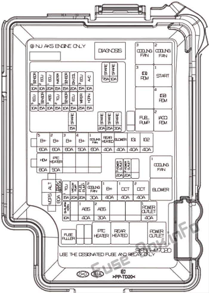
Assignment of the fuses in the Engine compartment (2019)
| Name | Amp rating | Circuit Protected |
|---|---|---|
| ALTERNATOR | 200A (NU 2.0L AKS) 150A (GAMMA 1.6LT-GDI) |
Fuses: BURGLAR ALARM, ABS1, ABS2, POWER OUTLET1, Alternator |
| MDPS | 80A | MDPS (Motor Driven Power Steering) Unit |
| B+5 | 60A | Fuse : ECU 3, ECU 4, HORN, WIPER, A/C, Engine Control Relay |
| B+2 | 60A | Instrument Panel Junction Block |
| B+3 | 60A | Instrument Panel Junction Block |
| B+4 | 50A | Instrument Panel Junction Block (Fuse : POWER WINDOW LH, POWER WINDOW RH, TRUNK, SUNROOF 1, SEAT HEATER FRONT, AMP, POWER SEAT DRIVER) |
| COOLING FAN 1 | 60A | GAMMA 1.6L T-GDI: Cooling Fan 1 Relay |
| REAR HEATED | 40A | Rear Heated Relay |
| BLOWER | 40A | BLOWER Relay |
| IG1 | 40A | Ignition Switch, PDM #2 (ACC) Relay, PDM #3 (IG1) Relay |
| IG2 | 40A | Ignition Switch, PDM #4 (IG2) Relay |
| PTC HEATER | 50A | PTC Heater Relay |
| POWER OUTLET 2 | 20A | Front Power Outlet |
| TCU 1 | 15A | GAMMA 1.6L T-GDI: TCM (Transmission Control Module) |
| VACUUM PUMP | 20A | GAMMA 1.6L T-GDI: Vacuum Pump |
| FUEL PUMP | 20A | Fuel Pump Relay |
| COOLING FAN 2 | 30A | NU 2.0L AKS: Cooling Fan 2 Relay, Cooling Fan 3 Relay |
| B+1 | 40A | Instrument Panel Junction Block (Long Term Load Latch Relay, Fuse : (BRAKE SWITCH, IBU 1, AIR BAG 2, DOOR LOCK, SEAT HEATER REAR, MODULE 1)) |
| DCT 1 | 40A | GAMMA 1.6L T-GDI: TCM (Transmission Control Module) |
| DCT 2 | 40A | GAMMA 1.6L T-GDI: TCM (Transmission Control Module) |
| ABS 1 | 40A | ABS (Anti-lock brake system) Module, ESC (Electronic Stability Control) Module, Multipurpose Check Connector |
| ABS 2 | 30A | ABS (Anti-lock brake system) Module, ESC (Electronic Stability Control) Module |
| POWER OUTLET 1 | 40A | Power Outlet Relay |
| SENSOR 2 | 10A | NU 2.0L AKS: Purge Control Solenoid Valve, Oil Control Valve #1/#2/#3, Canister Close Valve, Mass Air Folw Sensor, Fuel Filter Warning Sensor, A/Con Relay GAMMA 1.6L T-GDI: Purge Control Solenoid Valve, Oil Control Valve #1/#2, Canister Close Valve, RCV Control Solenoid Valve, E/R Junction Block (Cooling Fan Relay 1) |
| ECU 2 | 10A | GAMMA 1.6L T-GDI: ECM (Engine Control Module) |
| ECU 1 | 20A | NU 2.0L AKS: PCM (Power train Control Module) GAMMA 1.6L T-GDI: ECM (Engine Control Module) |
| INJECTOR | 15A | NU 2.0L AKS: Injector #1~#4 |
| SENSOR 1 | 15A | NU 2.0L AKS: Oxygen Sensor (Up), Oxygen Sensor (Down) GAMMA 1.6L T-GDI: Oxygen Sensor (Up), Oxygen Sensor (Down) |
| IGN COIL | 20A | Ignition Coil #1~#4 |
| ECU 3 | 15A | NU 2.0L AKS: PCM (Power train Control Module) GAMMA 1.6L T-GDI: ECM (Engine Control Module) |
| A/C | 10A | NU 2.0L AKS: A/Con Relay |
| ECU 5 | 10A | NU 2.0L AKS: PCM (Power train Control Module) GAMMA 1.6L T-GDI: ECM (Engine Control Module) |
| SENSOR 4 | 15A | GAMMA 1.6L T-GDI: Vacuum Pump |
| ABS 3 | 10A | ABS (Anti-lock brake system) Module, ESC (Electronic Stability Control) Module |
| TCU 2 | 15A | NU 2.0L AKS: Transaxle Range Switch GAMMA 1.6L T-GDI: Transaxle Range Switch, TCM |
| SENSOR 3 | 10A | NU 2.0L AKS: Fuel Pump Relay GAMMA 1.6L T-GDI: Fuel Pump Relay |
| ECU 4 | 15A | NU 2.0L AKS: PCM (Power train Control Module) GAMMA 1.6L T-GDI: ECM (Engine Control Module) |
| WIPER | 25A | Wiper Relay |
| HORN | 15A | Horn Relay |
Battery terminal cover