Fuse Layout Kia Telluride 2020-…
Contents

Cigar lighter (power outlet) fuses in the Kia Telluride are located in the Engine compartment fuse box (see fuses “POWER OUTLET 2” (Front Power Outlet), “POWER OUTLET 1” (Luggage Power Outlet) and “POWER OUTLET 3” (Rear Power Outlet)).
Table of Contents
Instrument panel fuse box
Instrument panel fuse box
Fuse box location
It is located behind the cover on the driver’s side of the instrument panel.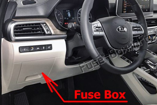
Fuse box diagram
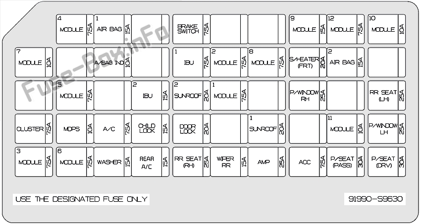
Assignment of the fuses in the Instrument panel (2020)
| Name | Amp rating | Protected component |
|---|---|---|
| MODULE 4 | 7.5 A | ATM (Auto Transmission) Shift Lever Switch, Stop Lamp Switch, Driver Door Module |
| AIR BAG 1 | 15 A | SRS (Supplemental Restraint System) Control Module, Passenger Occupant Detection Sensor |
| BRAKE SWITCH | 7.5 A | IBU (Integrated Body Control Unit), Stop Lamp Switch |
| MODULE 9 | 15 A | Front A/C Control Module, Low DC-DC Converter (Audio), Power Tail Gate Module, Driver IMS Control Module, Driver Door Module, Driver/Passenger Power Outside Mirror, |
| MODULE 12 | 7.5 A | Head-Up Display |
| MODULE 10 | 10 A | Blind-Spot Collision Warning Unit LH/RH, Front A/C Control Module, Rear A/C Control Module, Electro Chromic Mirror, Data Link Connector |
| AIR BAG IND | 10 A | Front A/C Control Module, Instrument Cluster |
| IBU 1 | 7.5 A | IBU (Integrated Body Control Unit) |
| MODULE 2 | 7.5 A | 360° camera monitoring system, AC Inverter Outlet, AC Inverter Unit, Front Air Ventilation Seat Control Module, Front Seat Warmer Control Module, 2ND Air Ventilation Seat Control Module LH/RH, 2ND Seat Warmer Control Module LH/RH |
| MODULE 8 | 7.5 A | Hazard Switch, Rain Sensor, Driver/Passenger Smart Key Outside Handle, Mood Lamp Control Unit, Driver/Passenger Mood Lamp, Driver/Passenger Door Mood Lamp, Rear Dooe Mood Lamp LH/RH |
| S/HEATER (FRT) | 20 A | Front Air Ventilation Control Module, Front Seat Warmer Control Module |
| AIR BAG 2 | 15 A | SRS (Supplemental Restraint System) Control Module |
| MODULE 5 | 7.5 A | Multifunction Camera Unit, Crash Pad Switch, IBU (Integrated Body Control Unit), Smart Cruise Control Radar, ATM (Auto Transmission) Shift Lever Indicator, 4WD ECM (Engine Control Module), Console Switch, Electric Parking Brake Switch |
| IBU 2 | 15 A | IBU (Integrated Body Control Unit) |
| SUNROOF 2 | 20 A | Rear Sunroof Controller |
| MODULE 1 | 7.5 A | IBU (Integrated Body Control Unit) |
| P/WINDOW RH | 25 A | Passenger Safety Power Window Module, Rear Safety Power Window Module RH |
| RR SEAT (LH) | 25 A | 2ND Air Ventilation Seat Control Module LH, 2ND Seat Warmer Control, Module LH, 2ND Seat LH Reclining Folding Actuator |
| CLUSTER | 7.5 A | Instrument Cluster, Head-Up Display |
| MDPS | 10 A | MDPS (Motor Driven Power Steering) Unit |
| A/C | 7.5 A | E/R Junction Block (Blower FRT Relay, Blower RR Relay, PTC Heater 1/2 Relay), Front A/C Control Module, Rear A/C Control Module |
| CHILD LOCK | 15 A | ICM (Integrated Circuit Module) Relay Box (Child Lock/Unlock Relay) |
| DOOR LOCK | 20 A | Door Lock Relay, Door Unlock Relay, Tail Gate Relay, T/Turn Unlock Relay |
| SUNROOF 1 | 20 A | Front Sunroof Controller |
| MODULE 11 | 10 A | Rear Occupant Detection Sensor |
| P/WINDOW LH | 25 A | Driver Safety Power Window Module, Rear Safety Power Window Module LH |
| MODULE 3 | 7.5 A | IBU (Integrated Body Control Unit) |
| MODULE 6 | 7.5 A | Audio, A/V & Navigation Head Unit, Low DC-DC Converter (Audio/AMP), Front A/C Control Module, Electro Chromic Mirror, Center fascia Keyboard, Driver/Passenger Seat Warmer Switch, Driver/Passenger Seat Warmer LIN Switch, Driver IMS Control Module, Rear Power Window Switch LH/ RH, Front Air Ventilation Control Module, Front Seat Warmer Control Module, 2ND Air Ventilation Seat Control Module LH/RH, 2ND Seat Warmer Control Module LH/RH |
| WASHER | 15 A | Multifunction Switch |
| RR SEAT (RH) | 25 A | 2ND Air Ventilation Seat Control Module RH, 2ND Seat Warmer Control, Module RH, 2ND Seat RH Reclining Folding Actuator |
| WIPER RR | 15 A | Rear Wiper Relay, Rear Wiper Motor |
| AMP | 25 A | Low DC-DC Converter (AMP) |
| ACC | 7.5 A | IBU (Integrated Body Control Unit), Low DC-DC Converter (Audio/AMP) |
| P/SEAT (PASS) | 30 A | Passenger Seat Manual Switch |
| P/SEAT (DRV) | 30 A | Driver IMS Control Module, Driver Seat Manual Switch |
Engine compartment fuse box
Engine compartment fuse box
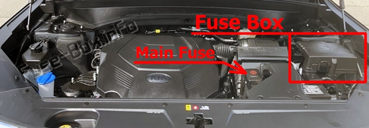
Fuse box location
Fuse box diagram
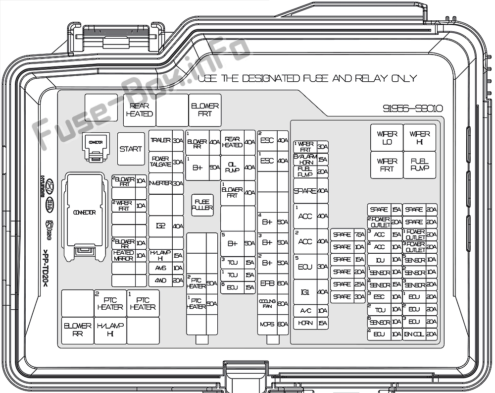
Assignment of the fuses in the engine compartment (2020)
| Name | Amp rating | Circuit Protected |
|---|---|---|
| MDPS | 80 A | MDPS (Motor Driven Power Steering) Unit |
| COOLING FAN | 80 A | Cooling Fan Controller |
| EPB | 60 A | ESC (Electronic Stability Control) Module |
| B+2 | 50 A | ICU Junction Block (IPS 8/IPS 10/IPS 11/IPS 12/IPS 13/IPS 14/1 PS 15) |
| B+3 | 50 A | ICU Junction Block (Fuse – P/WINDOW LH, RR SEAT (LH), P/SEAT (DRV), P/SEAT (PASS), MODULE 11) |
| B+4 | 50 A | ICU Junction Block (Fuse – MODULE 8, S/HEATER (FRT), P/ WINDOW RH, AMP, SUNROOF 1) |
| ESC 1 | 40 A | ESC (Electronic Stability Control) Module |
| ESC 2 | 40 A | ESC (Electronic Stability Control) Module |
| PTC HEATER 1 | 50 A | PTC Heater 1 Relay |
| PTC HEATER 2 | 50 A | PTC Heater 2 Relay |
| ECU 6 | 15 A | ECM (Engine Control Module) |
| TCU 1 | 15 A | TCM (Transmission Control Module) |
| TCU 3 | 15 A | TCM (Transmission Control Module) |
| B+5 | 50 A | ICU Junction Block (Fuse – DOOR LOCK, IBU (Integrated Body Control Unit) 1, IBU (Integrated Body Control Unit) 2, BRAKE SWITCH, CHILD LOCK, RR SEAT (RH), SUNROOF 2) |
| BLOWER FRT 1 | 40 A | Blower FRT Relay |
| OIL PUMP | 40 A | Electric Oil Pump Inverter |
| REAR HEATED | 40 A | Rear Heated Relay |
| B+1 | 50 A | ICU Junction Block (IPS 1 /IPS 2/IPS 3/IPS 5/IPS 6/IPS 7, Long/ Short Term Load Latch Relay) |
| BLOWER RR 1 | 40 A | Blower RR Relay |
| 4WD | 20 A | 4WD ECM (Engine Control Module) |
| AMS | 10 A | Battery Sensor |
| H/LAMP HI | 15 A | H/Lamp HI Relay |
| IG2 | 40 A | Start Relay, PCB Block (IG2 Relay) |
| INVERTER | 30 A | AC Inverter Unit |
| POWER TAIL GATE | 30 A | Power Tail Gate Module |
| TRAILER | 30 A | Trailer Connector |
| HEATED MIRROR | 10 A | Driver/Passenger Power Outside Mirror, Front A/C Control Module |
| BLOWER RR 2 | 10 A | Rear A/C Control Module |
| WIPER FRT 2 | 10 A | IBU (Integrated Body Control Unit) |
| BLOWER FRT 2 | 10 A | Front A/C Control Module |
| WIPER FRT 1 | 30 A | Wiper FRT Relay |
| B/ALARM HORN | 15 A | B/Alarm Horn Relay |
| FUEL PUMP | 20 A | Fuel Pump Relay |
| ACC 1 | 40 A | ACC 1 Relay |
| ACC 2 | 40 A | ACC 2 Relay |
| ECU 5 | 30 A | Engine Control Relay |
| IG1 | 40 A | IG1 Relay |
| A/C | 10 A | A/C Relay |
| HORN | 15 A | Horn Relay |
| POWER OUTLET 2 | 20 A | Front Power Outlet |
| ACC 3 | 15 A | Rear USB Charger, Luggage USB Charger, Driver/Passenger Seat Cushion USB Charger |
| ACC 4 | 10 A | Front USB Charger, Rear USB Charger RH |
| ICU | 10 A | ICU Junction Block (Fuse – ACC) |
| SENSOR 1 | 10 A | Fuel Pump Relay |
| SENSOR 4 | 15 A | Canister Close Valve, Oxygen Sensor #l/#2/#3/#4 |
| ESC 3 | 10 A | Data Link Connector, ESC (Electronic Stability Control) Module |
| TCU 2 | 10 A | TCM (Transmission Control Module), Transaxle Range Switch |
| SENSOR 6 | 10 A | Electric Oil Pump Inverter |
| ECU 4 | 10 A | ECM (Engine Control Module) |
| POWER OUTLET 1 | 20 A | Luggage Power Outlet |
| POWER OUTLET 3 | 20 A | Rear Power Outlet |
| SENSOR 5 | 10 A | Oil Pump Solenoid |
| SENSOR 2 | 10 A | A/C Relay, Purge Control Solenoid Valve, Oil Control Valve #l/#2/#3/#4 (Intake/Exhaust), Variable Intake Solenoid Valve #1 /#2, Electronic Thermostat |
| SENSOR 3 | 20 A | Cooling Fan Controller |
| ECU 1 | 20 A | ECM (Engine Control Module) |
| ECU 2 | 20 A | ECM (Engine Control Module) |
| ECU 3 | 20 A | ECM (Engine Control Module) |
| IGN COIL | 20 A | Ignition Coil #l/#2/#3/#4/#5/#6 |
| Relay Name | Type | |
| Blower FRT | MINI | |
| Rear Heated | MINI | |
| Start | MICRO | |
| PTC Heater 1 | MICRO | |
| PTC Heater 2 | MICRO | |
| H/LAMP HI | MICRO | |
| Blower RR | MICRO | |
| Wiper Lo | MICRO | |
| Wiper Hi | MICRO | |
| Wiper FRT | MICRO | |
| FUEL PUMP | MICRO |
Battery terminal (Main Fuse 250A)