

See other KIA Forte / Cerato:


Fuse Layout KIA Forte / Cerato 2009-2013
Contents

Cigar lighter (power outlet) fuses in the KIA Forte / Cerato are located in the Instrument panel fuse box (see fuses “P/OUTLET”).
Table of Contents
Instrument panel fuse box
Instrument panel fuse box
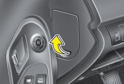
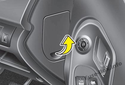
Fuse box location
It is located behind the cover on the driver’s side of the instrument panel.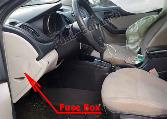
Left-hand drive vehicles
Right-hand drive vehicles
Assignment of the fuses in the Instrument panel
| Name | Amp rating | Protected component |
|---|---|---|
| START | 10A | Transaxle Range Switch (A/T), Ignition Lock Switch (M/T), E/R Fuse & Relay Box (Start Relay) |
| A/CON SW | 10A | A/C Control Module (Auto A/C), PCM |
| MIRR. HTD | 10A | Driver/ Passenger Power Outside Mirror (Defogger), A/C Control Module (Rear Defogger SW) |
| S/HTR | 15A | Front Seat Warmer LH/RH |
| A/CON | 10A | E/R Fuse & Relay Box (Blower Relay), BCM, Incar Temperature Sensor (Auto), Sunroof Control Module, A/C Control Module |
| HEAD LAMP | 10A | E/R Fuse & Relay Box (H/LP (HI/LO) Relay), DRL Control Module |
| WIPER (FR) | 25A | Multifunction Switch (Wiper & Washer SW), E/R Fuse & Relay Box (Wiper Relay), Front Wiper Motor |
| DRL | 15A | DRL Control Module |
| FOG LP (RR) | 15A | – |
| P/WDW DR | 25A | Power Window Main Switch, Rear Power Window Switch LH |
| D/CLOCK | 10A | Audio, BCM, Clock, Power Outside Mirror Switch |
| P/OUTLET | 15A | Power Outlet |
| DR LOCK | 20A | Sunroof Control Module, ICM Relay Box (Door Lock/Unlock Relay, Two Turn Unlock Relay) |
| DEICER | 15A | ICM Relay Box (Windshield Defogger Relay) |
| STOP LP | 15A | Stop Lamp Switch, Sport Mode Switch, Key Solenoid |
| POWER CONNECTOR: ROOM LP | 15A | Trunk Room Lamp, BCM, Clock, Instrument Cluster (IND.), Data Link Connector, A/C Control Module, Ignition Key III. & Door Warning Switch, Room Lamp, Map Lamp |
| POWER CONNECTOR: AUDIO | 15A | Audio |
| TRUNK OPEN | 15A | Trunk Open Relay |
| PDM | 25A | – |
| SAFETY P/WDW | 25A | – |
| P/WDW ASS | 25A | Power Window Main Switch, Passenger Power Window Switch, Rear Power Window Switch RH |
| P/OUTLET | 15A | Power Outlet |
| T/SIG LP | 10A | Hazard Switch |
| A/BAG IND | 10A | Instrument Cluster (IND.) |
| CLUSTER | 10A | Instrument Cluster (IND.), BCM, Electronic Chromic Mirror, Rheostat, Steering Angle Sensor |
| A/BAG | 15A | SRS Control Module |
| IGN1-A | 15A | PDM, EPMESC Switch, EPS Control Module Control Module |
| HAZARD LP | 15A | ICM Relay Box (Hazard Relay), Hazard Switch |
| TAIL LP (RH) | 10A | Rear Combination Lamp (In/Out) RH, Head Lamp RH, Shunt Connector, Passenger Power Window Switch, License Lamp RH (4DR), Illuminations, Rheostat Relay (With DRL) |
| TAIL LP (LH) | 10A | Head Lamp LH, Rear Combination Lamp (In/Out) LH, Power Window Main Switch, License Lamp (2DR), License Lamp LH (4DR) |
Engine compartment fuse box
Engine compartment fuse box
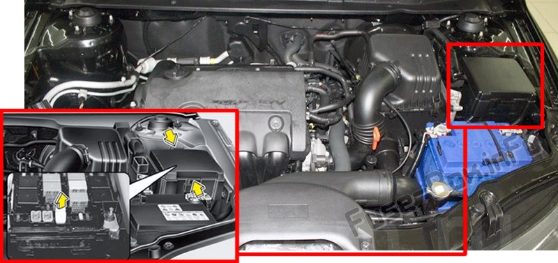
Fuse box location
Assignment of the fuses in the Engine compartment
| Description | Amp rating | Protected component |
|---|---|---|
| MULTI FUSES: | ||
| ALT | 125A | Generator, Fuse (MDPS, HTD GLASS, C/FAN, ABS 2, BLOWER, IGN 1, FOG LP (FR), ABS 1) |
| MDPS | 80A | EPS Control Module |
| ABS 2 | 40A | ESC Control Module, ABS Control Module |
| C/FAN | 40A | C/Fan LO/HI Relay |
| BLOWER | 40A | Blower Relay |
| HTD GLASS | 40A | I/P Junction Box (Rear Defogger Relay) |
| IGN 2 | 30A | Ignition Switch, Start Relay, Button Relay Box (ESCL Relay) |
| BATT 1 | 50A | I/P Junction Box (Fuse (TAIL LAMP (LH/RH), P/WDW DR, P/WDW ASS, FOG LP (RRJ/SSB, SMK, PDM), Tail Lamp Relay, Power Window Relay) |
| FUSES: | ||
| ABS 1 | 40A | ESC Control Module, ABS Control Module |
| IGN 1 | 30A | Ignition Switch, Button Relay Box (ESCL Relay (IGN 1)) |
| BATT 2 | 50A | I/P Junction Box (Power Connector (AUDIO, ROOM LP LAMP), FUSE (STOP LP, DEICER, HAZARD LP, DR LOCK, TRUNK OPEN)) |
| ECU | 30A | Engine Control Relay |
| FOG LP (FR) | 10A | Multipurpose Check Connector, Front Fog Relay, Battery Sensor |
| H/LP HI | 20A | H/LP (HI) Relay, |
| HORN | 10A | Horn Relay |
| H/LP LO(LH) | 10A | Head Lamp LH |
| H/LP LO(RH) | 10A | Head Lamp RH |
| SPARE | 10A | – |
| SNSR 3 | 10A | ECM, PCM, Vehicle Speed Sensor, Pulse Generator ‘A’, Stop Lamp Switch |
| ABS | 10A | Multipurpose Check Connector, ESC Control Module, ABS Control Module |
| ECU 3 | 15A | Ignition Coil (#1 —#4), Condenser, PCM |
| B/UP LP | 10A | Inhibitor Switch, Pulse Generater ‘B’, Back Up Lamp Switch |
| SPARE | 15A | – |
| SPARE | 20A | – |
| IGN COIL | 20A | Condenser (G4KF), Ignition Coil #1~4 |
| SNSR 2 | 10A | Oil Control Valve (#1, #2), Camshaft Position Sensor (Intake, Exhaust), F/PUMP Relay, C/FAN LO Relay, Immobilizer Module |
| ECU 2 | 10A | PCM, Purge Control Solenoid Valve, Oxygen Sensor (Down) |
| INJECTOR | 10A | A/CON Relay, Crankshaft Position Sensor, Oxygen Sensor (UP), Injector #1~4, Variable Intake Sensor |
| SNSR 1 | 15A | PCM, Canister Close Valve |
| ECU 1 | 10A | PCM |
| A/CON | 10A | A/CON Relay |
| F/PUMP | 15A | F/FUMP Relay |


