See other KIA Cadenza:

Fuse Layout KIA Cadenza 2017-2019…
Contents

Cigar lighter (power outlet) fuses in the KIA Cadenza are located in the Instrument panel fuse box (see fuse “POWER OUTLET” (Front Power Outlet, Rear Power Outlet)) and in the Engine compartment fuse box (see fuses “POWER OUTLET1 ” (Power Outlet Relay) and “POWER OUTLET2” (Front Power Outlet & Cigarette Lighter)).
Table of Contents
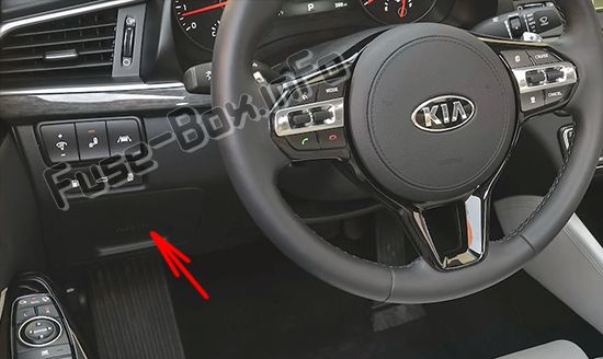
Fuse box location
Fuse box location
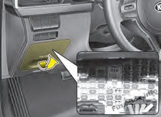
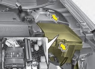
Instrument panel
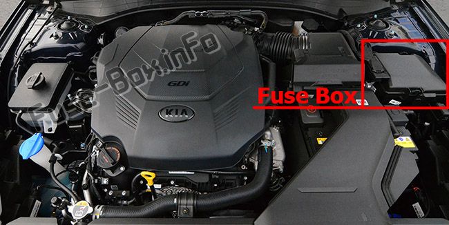
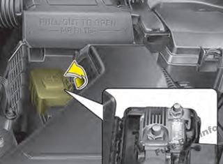
Engine compartment
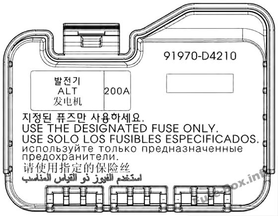
Main fuse
Fuse box diagrams
Fuse box diagrams
2017, 2018, 2019
Instrument panel
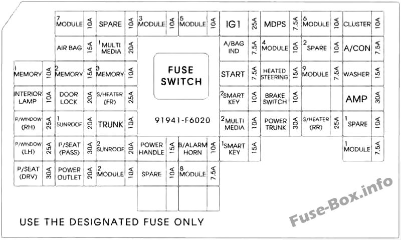
Assignment of the fuses in the Instrument panel
| Name | Amp rating | Circuit Protected |
|---|---|---|
| MODULE 7 | 10A | Driver Door Module, Passenger Door Module |
| SPARE | 10A | Spare |
| MODULE 3 | 10A | Stop Lamp Switch, BCM (Body Control Module), Sports Mode Switch |
| MODULE 5 | 10A | Console Switch, Blind Spot Detection Radar Left Handle side/Right Handle side, BCM (Body Control Module), Smart Cruise Control Unit, Crash Pad Switch, Fuel Filler & Trunk Open Switch, Lane Departure Warning Unit, Steering Tilt & Telescopic Module |
| IG1 | 25A | PCB (Printed Circuit Board) Block |
| MDPS | 7.5A | MDPS (Motor Driven Power Steering) Unit |
| MODULE 6 | 10A | Air Conditioner Switch, Air Conditioner Control Module, Electro Chromic Mirror, Head Lamp Left Handle side/Right Handle side, Auto Head Lamp Leveling Device Module, Front Seat Warmer Control Module, Front Air Ventilation Seat Control Module, Rear Seat Warmer Control Module, Audio/Video & Navigation Head Unit, Driver Integrated memory system Module, Auto Transmission Shift Lever Indicator, Multipurpose Check Connector |
| CLUSTER | 10A | Instrument Cluster, Head-Up Display |
| AIR BAG | 15A | SRS (Supplemental Restraint System) Control Module |
| MULTIMEDIA 1 | 20A | IGPM (Integrated Gateway Power control Module), Audio/Video & Navigation Head Unit |
| A/BAG IND | 7.5A | Air Conditioner Switch, Instrument Cluster |
| MODULE 4 | 10A | Smart Key Control Module, Immobilizer Module |
| SPARE 2 | 10A | Spare |
| A/CON | 7.5A | Air Conditioner Switch, Air Conditioner Control Module, Ionizer, Engine Room Junction Block (Blower Relay) |
| MEMORY 1 | 10A | Head-Up Display, Instrument Cluster, Wireless Charger Unit, Analog Clock, BCM (Body Control Module), Rain Sensor, Driver Door Module, Power Trunk Module, Passenger Door Module, Air Conditioner Switch, Air Conditioner Control Module, Security Indicator |
| MEMORY 2 | 15A | Driver Door Module |
| MEMORY 3 | 10A | Passenger Door Module |
| START | 7.5A | Transaxle Range Switch, ECM (Engine Control Module) |
| HEATED STEERING | 15A | BCM (Body Control Module) |
| MODULE 9 | 7.5A | Surround View Unit, Rear Seat Warmer Control Module, Front Seat Warmer Control Module, Front Air Ventilation Seat Control Module |
| WASHER | 15A | Multifunction Switch |
| INTERIOR LAMP | 10A | Glove Box Lamp, Passenger Foot Lamp, Driver Foot Lamp, Trunk Room Lamp, Front Vanity Lamp Switch Left Handle side/Right Handle side, Overhead Console Lamp, Room Lamp, Rear Personal Lamp Left Handle side/Right Handle side |
| DOOR LOCK | 20A | Door Lock/Unlock Relay |
| S/HEATER (FR) | 25A | Front Seat Warmer Control Module, Front Air Ventilation Seat Control Module |
| SMART KEY 2 | 10A | Start/Stop Button Switch |
| BRAKE SWITCH | 10A | Stop Lamp Switch, Immobilizer Module, Smart Key Control Module |
| AMP | 30A | AMP (Amplifier) |
| P/WINDOW (RH) | 25A | Passenger Safety Power Window Module, Rear Power Window Switch Right Handle side |
| SUNROOF 1 | 20A | Sunroof Control Unit (Glass) |
| TRUNK | 10A | Trunk Relay, Fuel Filler & Trunk Open Switch, Engine Room Junction Block(Fuel Lid Relay) |
| MULTIMEDIA 2 | 10A | Front Monitor |
| POWER TRUNK | 30A | Power Trunk Module |
| S/HEATER (RR) | 25A | Rear Seat Warmer Control Module |
| SPARE 1 | 10A | Spare |
| P/WINDOW (LH) | 25A | Rear Power Window Switch Left Handle side, Driver Safety Power Window Module |
| P/SEAT (PASS) | 30A | Passenger Seat Manual Switch |
| SUNROOF 2 | 20A | Sunroof Control Unit (Roller) |
| POWER HANDLE | 15A | Steering Tilt & Telescopic Module |
| B/ALARM HORN | 10A | Burglar Alarm Horn Relay |
| SMART KEY 1 | 15A | Smart Key Control Module |
| MODULE 1 | 7.5A | Data Link Connector, Hazard Switch, Console Switch |
| P/SEAT (DRV) | 30A | Driver Seat Manual Switch, Driver Integrated memory system Module |
| POWER OUTLET | 20A | Front Power Outlet, Rear Power Outlet |
| MODULE 2 | 10A | AMP (Amplifier), Surround View Unit, BCM (Body Control Module), Air Conditioner Control Module, Analog Clock, Wireless Charger Unit, Air Conditioner Switch, Smart Key Control Module, Front Monitor, Audio/Video & Navigation Head Unit, Engine Room Junction Block(Power Outlet Relay), USB Charger |
| SPARE | 10A | Spare |
| MODULE 8 | 7.5A | BCM (Body Control Module), Smart Key Control Module |
Engine compartment
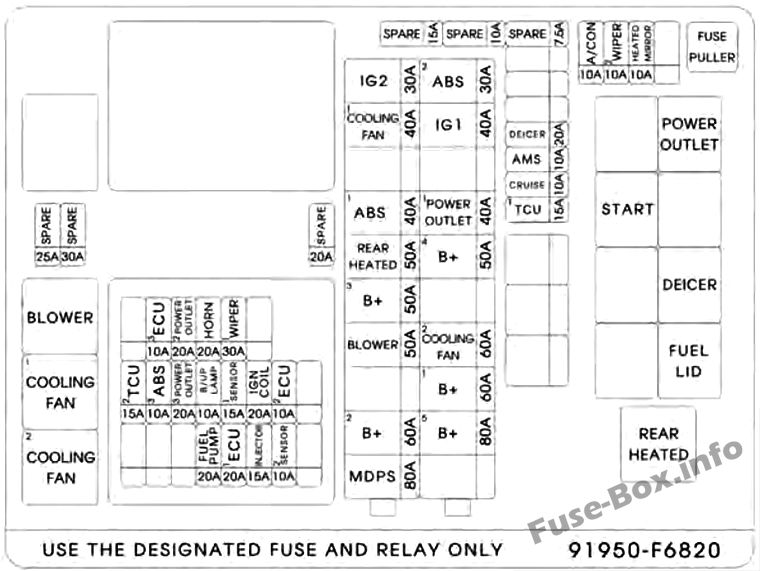
Assignment of the fuses in the Engine compartment
| Name | Amp rating | Circuit Protected |
|---|---|---|
| MULTI FUSES: | ||
| MDPS | 80A | MDPS (Motor Driven Power Steering) UNIT |
| B+2 | 60A | IGPM (Integrated Gateway Power control Module) |
| BLOWER | 50A | Blower Relay |
| B+3 | 50A | IGPM (Integrated Gateway Power control Module) |
| REAR HEATED | 50A | Rear Heated Relay |
| ABS1 | 40A | ESC (Electronic Stability Control) Module |
| IG2 | 30A | Without Smart Key : Start Relay, Ignition Switch; With Smart Key : Start Relay |
| B+5 | 80A | WIPER1, HORN, ECU2, FUEL PUMP, Engine Control Relay |
| B+1 | 60A | IGPM (Integrated Gateway Power control Module) |
| COOLING FAN 2 | 60A | Cooling Fan1 Relay, Cooling Fan2 Relay |
| B+4 | 50A | IGPM (Integrated Gateway Power control Module) |
| POWER OUTLET1 | 40A | Power Outlet Relay |
| IG1 | 40A | Without Smart Key : Ignition Switch; With Smart Key : Ignition switch 1, ACC Relay |
| ABS2 | 30A | ESC (Electronic Stability Control) Control Module, Multipurpose Check Connector |
| FUSES: | ||
| TCU1 | 15A | TCM (Transmission Control Module) |
| CRUISE | 10A | Smart Cruise Control Unit |
| AMS | 10A | Battery Sensor |
| DEICER | 20A | Front Deicer Relay |
| A/CON | 10A | Air Conditioner Control Module |
| WIPER2 | 10A | BCM (Body Control Module), ECM (Engine Control Module) |
| HEATED MIRROR | 10A | Air Conditioner Switch, Driver/Passenger Power Outside Mirror |
| ECU3 | 10A | ECM (Engine Control Module) |
| POWER OUTLET2 | 20A | Front Power Outlet & Cigarette Lighter |
| HORN | 20A | Horn Relay |
| WIPER1 | 30A | Wiper Power Relay |
| TCU2 | 15A | TCM (Transmission Control Module), Transaxle Range Switch |
| ABS3 | 10A | ESC (Electronic Stability Control) Module |
| POWER OUTLET3 | 20A | Not Used |
| B/UP LAMP | 10A | Electro Chromic Mirror, Rear Combination Lamp (Inside) Left Handle side/Right Handle side |
| SENSOR1 | 15A | Oxygen Sensor #1~#4 |
| IGN COIL | 20A | Ignition Coil #1~#6 |
| ECU2 | 10A | ECM (Engine Control Module) |
| FUEL PUMP | 20A | Fuel Pump Relay |
| ECU1 | 20A | ECM (Engine Control Module) |
| INJECTOR | 15A | Not Used |
| SENSOR2 | 10A | Variable Intake Solenoid Valve #1, #2, Electronic Thermostat, Purge Control Solenoid Valve, Canister Close Valve, Oil Pressure Solenoid Valve, Oil Control Valve #1~#4, Cooling Fan1 Relay, Cooling Fan2 Relay, Fuel Pump Relay |
Assignment of the relays
| Relay Name | Type |
|---|---|
| Blower Relay | MINI |
| Cooling Fan1 Relay | MINI |
| Cooling Fan2 Relay | MINI |
| Power Outlet Relay | MICRO |
| Start Relay | MICRO |
| Front Deicer Relay | MICRO |
| Fuel Filler Relay | MICRO |
| Rear Heated Relay | MINI |
Main fuse (Battery terminal cover)