See other KIA Cadenza:

Fuse Layout KIA Cadenza 2010-2016
Contents

Cigar lighter (power outlet) fuses are located in the Instrument panel fuse box (see fuses “C/LIGHTER” (Cigarette lighter) and “POWER OUTLET” (Console Power Outlet)).
Table of Contents
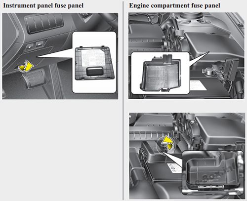
Fuse box location
Fuse box location
Instrument panel
The fuse box is located behind the cover to the left of the steering wheel.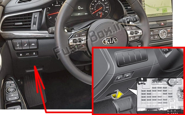
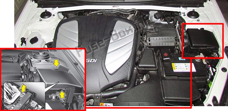
Engine compartment
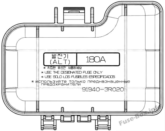
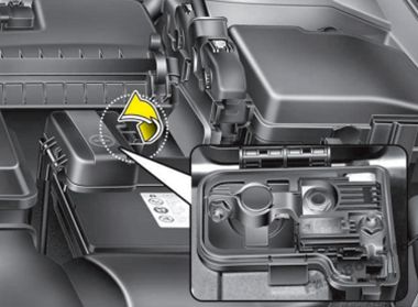
Main fuse
2011
2011
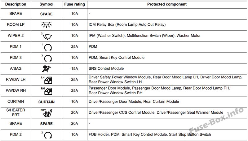
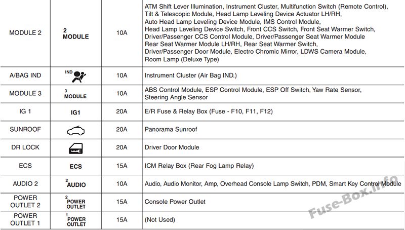
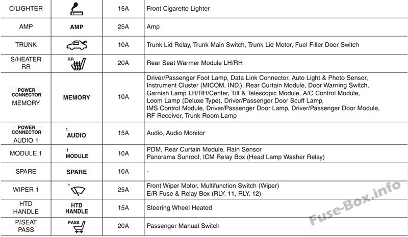
Assignment of the fuses in the Instrument panel (2011)
Assignment of the fuses in the Engine compartment (2011)
2012
2012
Assignment of the fuses in the Instrument panel (2012)
Assignment of the fuses in the Engine compartment (2012)

Fuse box diagrams 2014, 2015, 2016
Fuse box diagrams 2014, 2015, 2016
Instrument panel
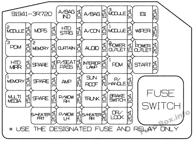
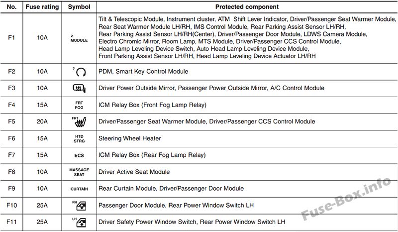
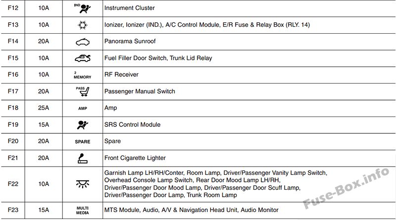
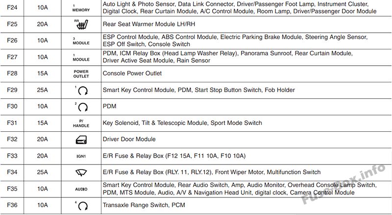
Assignment of the fuses in the Instrument panel (2014, 2015, 2016)
| № | Amp rating | Description | Protected component |
|---|---|---|---|
| MF1 | 10A | MODULE 2 | Tilt & Telescopic Module, Instrument cluster, Driver/Passenger Seat Warmer Module, Rear Seat Warmer Module LH/RH, IMS Control Module, Rear Parking Assist Sensor LH/RH, Rear Parking Assist Sensor LH/RH(Center), Driver/Passenger Door Module, LDWS Camera Module, Electro Chromic Mirror, Room Lamp, MTS Module, Driver/Passenger CCS Control Module, Head Lamp Leveling Device Switch, Auto Head Lamp Leveling Device Module, Front Parking Assist Sensor LH/RH, Head Lamp Leveling Device Actuator LH/RH, Console SW, BSD (Blind Spot Detection) Unit LH/RH Rear P/WDW HEATED Module |
| MF2 | 10A | PDM 3 | PDM, Smart Key Control Module |
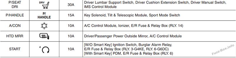
| MF3 | 10A | HTD MRR | Driver Power Outside Mirror, Passenger Power Outside Mirror, A/C Control Module |
| MF4 | 10A | MEMORY 1 | Auto Light & Photo Sensor, Data Link Connector, Driver/Passenger Foot Lamp, Instrument Cluster, Digital Clock, Rear Curtain Module, A/C Control Module, Room Lamp, Driver/Passenger Door Module |
| MF5 | 15A | MULTIMEDIA | MTS Module, Audio, A/V & Navigation Head Unit, Audio Monitor |
| MF6 | 10A | MDPS | MDPS_SIG |
| MF7 | 10A | MEMORY 2 | RF Receiver |
| MF8 | 15A | SPARE | SPARE |
| MF9 | 10A | SPARE | SPARE |
| MF10 | 15A | SPARE | SPARE |
| MF11 | 20A | S/HEATER FRT | Driver/Passenger Seat Warmer Module, Driver/Passenger CCS Control Module |
| MF12 | 10A | A/BAG IND | Instrument Cluster |
| MF13 | 15A | HTD STRG | Steering Wheel Heater |
| MF14 | 10A | CURTAIN | Rear Curtain Module, Driver/Passenger Door Module |
| MF15 | 20A | P/SEAT PASS | Passenger Manual Switch |
| MF16 | 25A | AMP | AMP |
| MF17 | 25A | P/WDW RH | Passenger Door Module, Rear Power Window Switch RH |
| MF18 | 25A | P/WDW LH | Driver Safety Power Window Switch, Rear Power Window Switch LH |
| MF19 | 15A | A/BAG | SRS Control Module |
| MF20 | 10A | A/CON | Ionizer, Ionizer (IND.), A/C Control Module, E/R Fuse & Relay Box (RLY. 14) |
| MF21 | 10A | AUDIO | Smart Key Control Module, Rear Audio Switch, Amp, Audio Monitor, Overhead Console Lamp Switch, PDM, MTS Module, Audio, A/V & Navigation Head Unit, digital clock |
| MF22 | 10A | INTERIOR LAMP | Garnish Lamp LH/RH/Conter, Room Lamp, Driver/Passenger Vanity Lamp Switch, Overhead Console Lamp Switch, Rear Door Mood Lamp LH/RH, Driver/Passenger Door Mood Lamp, Driver/Passenger Door Scuff Lamp, Driver/Passenger Door Lamp, Trunk Room Lamp |
| MF23 | 20A | SUNROOF | Panorama Sunroof |
| MF24 | 10A | TRUNK | Fuel Filler Door Switch, Trunk Lid Relay |
| MF25 | 20A | S/HEATER RR | Rear Seat Warmer Module LH/RH |
| MF26 | 10A | MODULE 3 | ESP Control Module, ABS Control Module, Electric Parking Brake Module, Steering Angle Sensor, ESP Off Switch, Console Switch |
| MF27 | 10A | MODULE 1 | PDM, ICM Relay Box (Head Lamp Washer Relay), Panorama Sunroof, Rear Curtain Module, Driver Active Seat Module, Rain Sensor |
| MF28 | 15A | POWER OUTLET | Console Power Outlet |
| MF29 | 25A | PDM | Smart Key Control Module, Fob Holder |
| MF30 | 15A | P/HANDLE | Key Solenoid, Tilt & Telescopic Module, Sport Mode Switch |
| MF31 | 10A | BRAKE SWITCH | PDM, Start Stop Button Switch |
| MF32 | 20A | DR/LOCK | Driver Door Module |
| MF33 | 20A | IG1 | E/R Fuse & Relay Box (F12 15A, F11 10A, F10 10A) |
| MF34 | 25A | WIPER | E/R Fuse & Relay Box (RLY. 11, RLY.12), Front Wiper Motor, Multifunction Switch |
| MF35 | 20A | C/Lighter | Front Cigarette Lighter |
| MF36 | 10A | START | Transaxle Range Switch, PCM |
Engine compartment
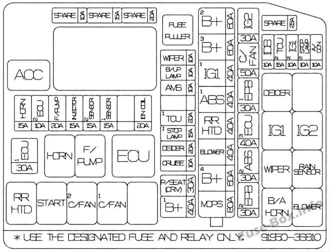
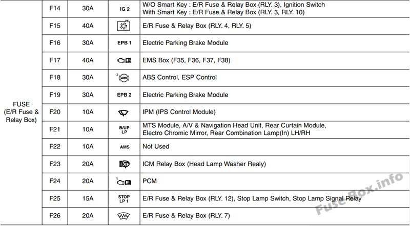
Assignment of the fuses in the Engine compartment (2014, 2015, 2016)
| № | Amp rating | Description | Protected component |
|---|---|---|---|
| MULTI FUSES: | |||
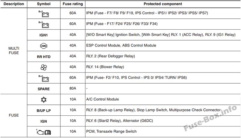
| F1 | 60A | 2 B+ | IPM (F7, F8, F9, F10, F11, IPS1, IPS2, IPS3, IPS5, IPS7) |
| F2 | 60A | 3 B+ | IPM (F14, F15, F17, F18, F25) |
| F3 | 40A | IG1 | W/O Smart Key : Ignition Switch; With Smart Key : E/R Fuse & Relay Box (RLY. 1, RLY. 9) |
| F4 | 40A | 1 ABS | ABS Control,ESP Control |
| F5 | 40A | RR HTD | E/R Fuse & Relay Box (RLY 2) |
| F6 | 40A | BLOWER | E/R Fuse & Relay Box (RLY 14) |
| F7 | 60A | 4 B+ | IPM (F4, F5, IPS 0, IPS 4, IPS 6) |
| F8 | 80A | MDPS | MDPS_PWR |
| FUSE (E/R Fuse & Relay Box): | |||
| F9 | 10A | A/CON | A/C Control Module |
| F10 | 10A | STOP LAMP | E/R Fuse & Relay Box (RLY 8), Stop Lamp Switch, Multipurpose Check Connector |
| F11 | 10A | IG1 | Alternator, PCM |
| F12 | 15A | T2 TCU | Transaxle Range Switch |
| F13 | 10A | IDB | IDB_LAG |
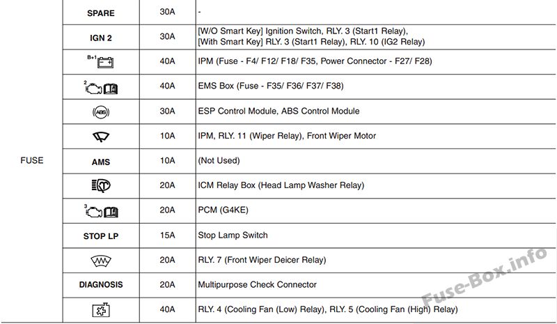
| F14 | 30A | IG2 | W/O Smart Key : E/R Fuse & Relay Box (RLY. 3), Ignition Switch; With Smart Key : E/R Fuse & Relay Box (RLY. 3, RLY 10) |
| F15 | 50A | C/FAN | E/R Fuse & Relay Box (RLY 4, RLY 5) |
| F16 | 30A | 1 EPB | Electric Parking Brake Module |
| F17 | 40A | 3 ECU | EMS Box (F35, F36, F37, F38) |
| F18 | 30A | 2 ABS | ABS Control, ESP Control |
| F19 | 30A | 2 EPB | Electric Parking Brake Module |
| F20 | 10A | WIPER | IPM (IPS Control Module) |
| F21 | 10A | B/UP LAMP | MTS Module, A/V & Navigation Head Unit, Rear Curtain Module, Electro Chromic Mirror, Rear Combination Lamp(ln) LH/RH |
| F22 | 10A | AMS | Not Used |
| F23 | 20A | – | ICM Relay Box (Head Lamp Washer Realy) |
| F24 | 20A | TCU | PCM |
| F25 | 15A | 1 STOP LAMP | E/R Fuse & Relay Box (RLY 12), Stop Lamp Switch, Stop Lamp Signal Relay |
| F26 | 20A | DEICER | E/R Fuse & Relay Box (RLY 7) |
| F27 | 10A | CRUISE | SCC (Smart Cruise Control) Radar |
| F28 | 30A | P/SEAT (DRV) | IMS Control Module, Driver Lumbar Support Switch, Driver Cushion Extension Switch, Driver Manual Switch |
| F29 | 40A | 1 B+ | IPM (F29, F30, F31, F32, IPS 11, Leak Current Autocut Device) |
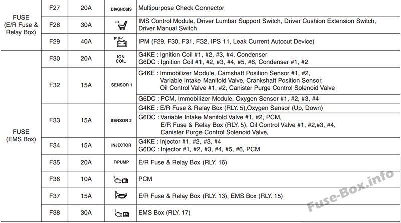
| FUSE (EMS Box): | |||
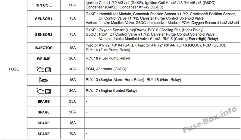
| F30 | 20A | IGN COIL | G4KE : Ignition Coil #1, #2, #3, #4, Condenser; G6DC : Ignition Coil #1, #2, #3, #4, #5, #6, Condenser #1, #2 |
| F31 | 15A | 1SENSOR | G4KE : Immobilizer Module, Camshaft Position Sensor #1, #2, Variable Intake Manifold Valve, Crankshaft Position Sensor, Oil Control Valve #1, #2, Canister Purge Control Solenoid Valve; G6DC : PCM, Immobilizer Module, Oxygen Sensor #1, #2, #3, #4 |
| F32 | 15A | 2SENSOR | G4KE : E/R Fuse & Relay Box (RLY. 5),Oxygen Sensor (Up, Down); G6DC : Variable Intake Manifold Valve #1, #2, PCM, E/R Fuse & Relay Box (RLY. 5), Oil Control Valve #1, #2,#3, #4, Canister Purge Control Solenoid Valve, |
| F33 | 15A | INJECTOR | G4KE : Injector #1, #2, #3, #4; G6DC : Injector #1, #2, #3, #4, #5, #6, PCM |
| F34 | 20A | F/FUMP | E/R Fuse & Relay Box (RLY 16) |
| F35 | 10A | 2 ECU | PCM |
| F36 | 15A | HORN | E/R Fuse & Relay Box (RLY 13), EMS Box (RLY 15) |
| F37 | 30A | 1 ECU | EMS Box (RLY 17) |
Main fuse