


Fuse Layout Hyundai Elantra GT 2018-2019…
Contents

Cigar lighter (power outlet) fuses in the Hyundai Elantra GT are located in the Instrument panel fuse box (see fuse “POWER OUTLET” (Rear Power Outlet #2)) and in the Engine compartment fuse box (see fuses “POWER OUTLET 3” (Rear Power Outlet 1) and “Rear Power Outlet 2” (Front Power Outlet)).
Table of Contents
Fuse box location
Fuse box location
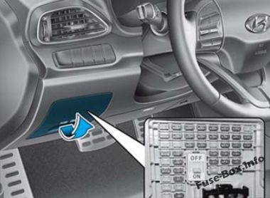
Instrument panel
The fuse box is located on the driver’s side of the instrument panel behing the cover.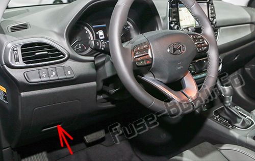
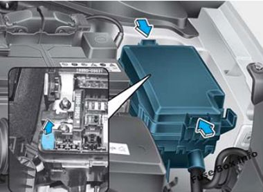
Engine compartment
The fuse box is located in the engine compartment (left-side).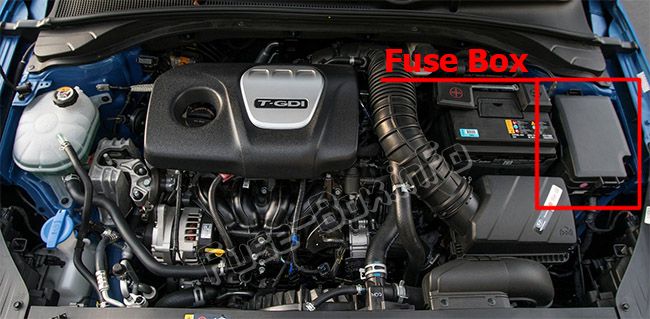
Fuse box diagrams
Fuse box diagrams
2018
Instrument panel
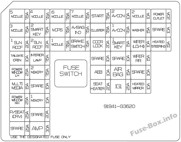
Assignment of the fuses in the instrument panel (2018)
| Name | Amp Rating | Protected Component |
|---|---|---|
| MODULE 5 | 7.5A | Crash Pad Switch, Electro Chromic Mirror, A/V & Navigation Head Unit, A/C Control Module, A/T Shift Lever Indicator, Console Switch LH, Head Lamp Leveling Device LH/RH, Front Seat Warmer Control Module, Front Air Ventilation Seat Control Module |
| MODULE 3 | 7.5A | BCM, Sport Mode Switch |
| SUNROOF 1 | 20A | Panorama Sunroof |
| TAIIGATE OPEN | 10A | Tail Gate Relay |
| P/WDW (LH) | 25A | Power Window LH Relay, Driver/Passenger Safety Window Module |
| MULTIMEDIA | 15A | A/V & Navigation Head Unit |
| P/WDW (RH) | 25A | Power Window RH Relay |
| P/SEAT DRV | 25A | Driver Seat Manual Switch |
| MODULE 4 | 7.5A | Lane Keeping Assist Module, Blind Spot Detection Radar LH/RH, Stop Lamp Switch, Electric Parking Brake Switch, Autonomous Emergency Braking Module |
| SMART KEY 2 | 7.5A | Smart Key Control Module, Immobilizer Module |
| SUNROOF 2 | 20A | Panorama Sunroof |
| INTERIOR LAMP | 7.5A | Wireless Charger, Vanity Lamp LH/RH, Room Lamp, Overhead Console Lamp, Personal Lamp LH/RH |
| MEMORY 2 | 7.5A | BCM |
| MEMORY 1 | 10A | A/C Control Module, Instrument Cluster, Auto Light & Photo Sensor, Electro Chromic Mirror, ICM Relay Box (Outside Mirror Folding/Unfolding Relay) |
| AMP | 30A | AMP |
| MODULE 6 | 7.5A | Smart Key Control Module, BCM |
| MDPS | 7.5A | MDPS Unit |
| MODULE 1 | 7.5A | Hazard Switch, Center Door Lock Switch, Ignition Key Interlock Switch, Driver/Passenger Smart Key Outside Handle, Data Link Connector |
| MODULE 7 | 7.5A | Front Seat Warmer Control Module, Front Air Ventilation Seat Control Module |
| A/BAG IND | 7.5A | Instrument Cluster, Center Door Lock Switch |
| BRAKE SWITCH | 7.5A | Smart Key Control Module, Stop Lamp Switch |
| START | 7.5A | Without Smart Key: Ignition Key Switch With Smart Key : Smart Key Control Module |
| CLUSTER | 7.5A | Instrument Cluster |
| DR LOCK | 20A | Door Lock/Unlock Relay, ICM Relay Box (T/Turn Unlock Relay) |
| AEB | 10A | Autonomous Emergency Braking Module |
| S/HEATER | 20A | Front Seat Warmer Control Module, Front Air Ventilation Seat Control Module |
| A/CON | 7.5A | A/C Control Module, Cluster Ionizer, E/R Junction Block (Blower Relay) |
| SMART KEY 1 | 15A | Smart Key Control Module, Immobilizer Module |
| A/BAG | 15A | SRS Control Module |
| IG1 | 25A | PCB Block (ABS3, ECU5, SENSOR4, TCU2) |
| MODULE 2 | 10A | Wireless Charger, Smart Key Control Module, BCM, A/V & Navigation Head Unit, Power Outside Mirror Switch, E/R Junction Block (Power Outlet Relay), AMP |
| WASHER | 15A | Multifunction Switch |
| WIPER (LO/HI) | 10A | ECM/PCM, BCM |
| WIPER (RR) | 15A | Rear Wiper Relay, Rear Wiper Motor |
| HEATED MIRROR | 10A | Driver/Passenger Power Outside Mirror, A/C Control Module, ECM/PCM |
| POWER OUTLET | 20A | Rear Power Outlet #2 |
| HEATED STEERING | 15A | BCM |
Engine compartment
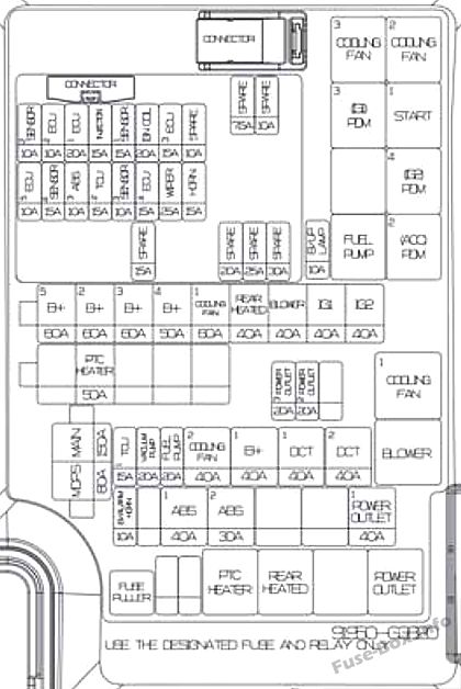
Assignment of the fuses in the Engine compartment (2018)
| Name | Amp Rating | Protected Component |
|---|---|---|
| MAIN | 150A | E/R Junction Block (Fuse – ABS1, ABS2, B/Alarm, Power Outlet – !) |
| MDPS 1 | 80A | MDPS Unit, Battery |
| B+5 | 60A | PCB Block (Fuse – ECU4, ECU3, Horn, Wiper, Engine Control Relay) |
| B+2 | 60A | IGPM (Fuse – S/Heater, IPSO, IPS1, IPS2) |
| B+3 | 60A | IGPM (IPS3, IPS4, IPS5, IPS6, IPS7, IPS8) |
| B+4 | 60A | IGPM (Fuse – AMP, P/WDW LH, P/WDW RH, Tail Gate Open, Sunroofl, Sunroof2, P/Seat (DRV)) |
| COOLING FAN 1 | 60A | E/R Junction Block (Cooling Fan1 Relay) |
| REAR HEATED | 40A | E/R Junction Block (Rear Heated Relay) |
| BLOWER | 40A | E/R Junction Block (Blower Relay) |
| IG1 | 40A | Ignition Switch, E/R Junction Block (ACC Relay, IG1 Relay) |
| IG2 | 40A | Ignition Switch, E/R Junction Block (IG2 Relay) |
| PTC HEATER 1 | 50A | PTC Heaterl |
| POWER OUTLET 3 | 20A | Rear Power Outlet 1 |
| POWER OUTLET 2 | 20A | Front Power Outlet |
| TCU1 | 15A | TCM |
| VACUUM PUMP | 20A | Vacuum Pump |
| FUEL PUMP | 20A | E/R Junction Block (Fuel Pump Relay) |
| COOLING FAN 2 | 40A | E/R Juntion Block (Cooling Fan2 Relay, Cooling Fan3 Relay) |
| B+1 | 40A | IGPM (Fuse – Door Lock, Smart Key1, Module 1, Brake Switch, Reak Current Autocut Device) |
| DOT 1 | 40A | TCM |
| DOT 2 | 40A | TCM |
| B/ALARM HORN | 10A | ICM Relay Box (Burglar Alarm Horn Relay) |
| ABS 1 | 40A | Multipurpose Check Connector, ESC Control Module |
| ABS 2 | 30A | Multipurpose Check Connector, ESC Control Module |
| POWER OUTLET 1 | 40A | E/R Junction Block (Power Outlet Relay) |
| B/UP LAMP | 10A | Back-Up Lamp Switch |
| GAMMA 1.6LT-GDI: | ||
| SENS0R2 | 10A | Waste Gate Valve, Purge Control Solenoid Valve, Oil Control Valve #1/#2, RCV Control Solenoid Valve, E/R Junction Block (Cooling Fan2 Relay, Cooling Fan1 Relay) |
| ECU2 | 10A | ECM |
| ECU1 | 20A | ECM |
| SENS0R1 | 15A | Oxygen Sensor (Up), Oxygen Sensor (Down) |
| IGN COIL | 20A | Ignition Coil #1/#2/#3/#4 |
| ECU3 | 15A | ECM |
| ECU5 | 10A | ECM |
| SENSOR4 | 15A | Vaccum Pump |
| ABS3 | 10A | ESC Control Module, Multipurpose Check Connector, Clutch Master Cylinder |
| TCU2 | 15A | E/R Junction Block (Fuse – B/Up Lamp), Transaxle Range Switch, TCM |
| SENSOR3 | 10A | E/R Junction Block (Fuel Pump Relay) |
| ECU4 | 15A | ECM |
| WIPER | 25A | Wiper Relay |
| HORN | 15A | Horn Relay |
| NU 2.0L GDI: | ||
| SENS0R2 | 10A | Purge Control Solenoid Valve, Oil Control Valve #1/#2, Variable Intake Solenoid Valve, E/R Junction Block (Cooling Fan2 Relay, Cooling Fan3 Relay) |
| ECU2 | 10A | ECM/PCM |
| ECU1 | 20A | ECM/PCM |
| SENS0R1 | 15A | Oxygen Sensor (Up), Oxygen Sensor (Down) |
| IGN COIL | 20A | Ignition Coil #1/#2/#3/#4, Condenser |
| ECU3 | 15A | ECM/PCM |
| ECU5 | 10A | ECM/PCM |
| ABS3 | 10A | ABS/ESC Control Module, Multipurpose Check Connector |
| ABS3 | 15A | E/R Junction Block (Fuse – B/Up Lamp), Transaxle Range Switch, TCM |
| SENSOR3 | 10A | E/R Junction Block (Fuel Pump Relay) |
| WIPER | 25A | Wiper Relay |
| HORN | 15A | Horn Relay |
Battery terminal cover