

Fuse Layout Hyundai Venue 2020-…
Contents

Table of Contents
Fuse box location
Fuse box location
Passenger Compartment Fuse Box
The fuse box is located behind the cover on the driver’s side of the instrument panel. Turn the engine off, turn all other switches OFF, open the fuse panel cover.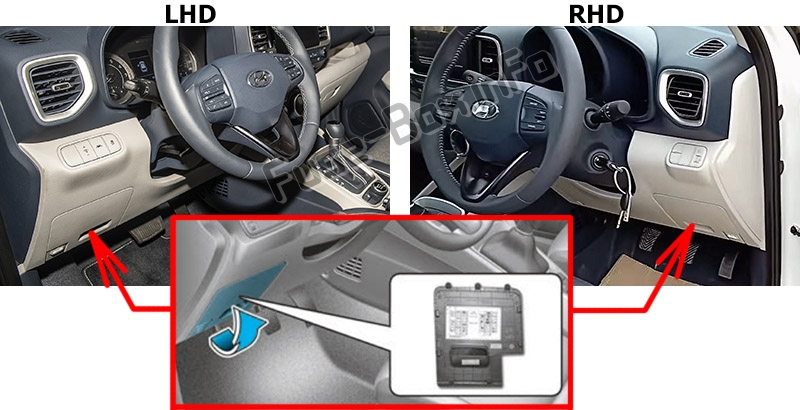
Engine Compartment Fuse Box
Turn the engine off, turn all other switches OFF, remove the cover by pressing the tab and pulling up.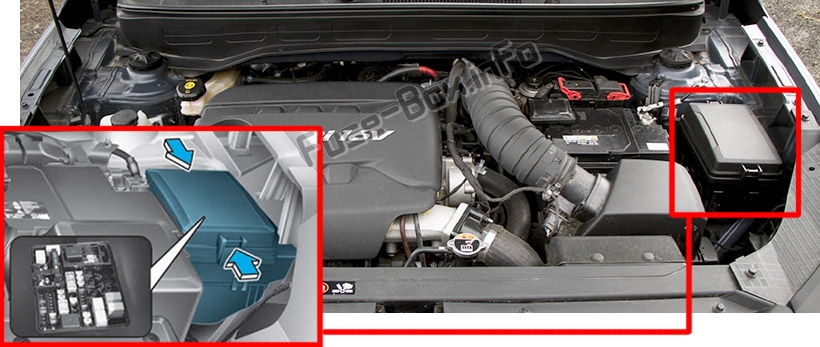
Fuse box diagrams
Fuse box diagrams
2020
Passenger Compartment
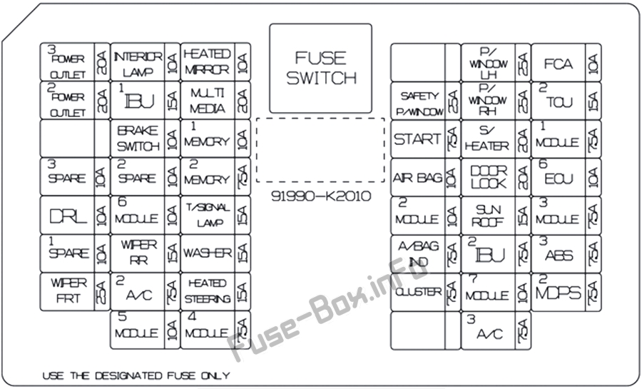
Assignment of the fuses in the Instrument panel (2020)
| Name | Amp Rating | Description |
|---|---|---|
| POWER OUTLET 3 | 20A | USB Charger |
| INTERIOR LAMP | 10A | Front Vanity Lamp LH/RH, Room Lamp, Map Lamp |
| HEATED MIRROR | 10A | Driver/Passenger Power Outside Mirror, A/C Control Module |
| P/WINDOW LH | 25A | Power Window Main Switch |
| FCA | 10A | Forward Collision Avoidance Assist Unit |
| POWER OUTLET 2 | 20A | Front Power Outlet |
| IBU 1 | 15A | IBU |
| MULTIMEDIA | 20A | Audio, A/V & Navigation Head Unit |
| SAFETY P/WINDOW | 25A | Driver Safety Power Window Module |
| P/WINDOW RH | 25A | Power Window Main Switch, Passenger Power Window Switch |
| TCU2 | 15A | Transaxle Range Switch, Back-Up Lamp Switch |
| BRAKE SWITCH | 10A | IBU, Stop Lamp Switch |
| MEMORY 1 | 10A | Instrument Cluster, A/C Control Module |
| START | 7.5 A | M/T: ECM, IBU; IVT: Transmission Range Switch |
| S/HEATER | 20A | Front Seat Warmer Control Module |
| MODULE 1 | 7.5A | Stop Lamp Switch, ATM Shift Lever |
| MEMORY 2 | 7.5A | SRS Control Module |
| AIRBAG | 10A | Passenger Occupant Detection Sensor, SRS Control Module |
| DOOR LOCK | 20A | Tail Gate Relay, T/Turn Unlock Realy, Door Lock/Unlock Realy |
| ECU 6 | 10A | ECM, PCM |
| DRL | 10A | DRL Relay |
| MODULE 6 | 10A | Data Link Connector, Key Interlock Solenoid |
| T/SIGNAL LAMP | 15A | IBU |
| MODULE 2 | 10A | Crash Pad Switch, Multifunction Camera Unit, Blind Spot Collision Warning Unit LH/RH |
| SUNROOF | 15A | Sunroof Motor |
| MODULE 3 | 7.5A | Console Switch, ATM Shift Lever Indicator, A/C Control Module, Audio, Front Seat Warmer Control Module |
| WIPER RR | 15A | E/R Junction Block (Wiper RR Relay), Rear Wiper Motor |
| WASHER | 15A | Multifunction Switch |
| A/BAG IND | 7.5 A | Center Facia Switch, Instrument Cluster |
| IBU 2 | 7.5 A | IBU |
| ABS3 | 7.5 A | E/R Junction Block (Multipurpose Check Connector), ESC Module |
| WIPER FRT | 25A | E/R Junction Block (Wiper FRT Low Relay), Front Wiper Motor |
| A/C 2 | 7.5 A | E/R Junction Block (Blower Relay), A/C Control Module |
| HEATED STEERING | 15A | Not Used |
| CLUSTER | 7.5 A | Instrument Cluster |
| MODULE 7 | 10A | Power Outlet Relay, Power Outside Mirror Switch, IBU, Audio, A/V & Navigation Head Unit |
| MDPS2 | 7.5 A | MDPS Unit |
| MODULE 5 | 10A | IBU, Front Seat Warmer Control Module |
| MODULE 4 | 7.5 A | IBU |
| A/C 3 | 7.5 A | Blower Motor, A/C Control Module |
Engine Compartment
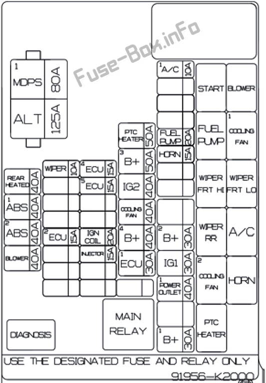
Assignment of the fuses in the engine compartment (2020)
| Name | Amp Rating | Description |
|---|---|---|
| ALT | 125A | Alternator, Multi Fuse – MDPS 1, Fuse – Rear Heated, Blower, ABS 1, ABS 2 |
| MDPS1 | 80A | MDPS Unit |
| REAR HEATED | 40A | ICU Junction Block (Rear Heated Relay) |
| ABS1 | 40A | Multipurpose Check Connector, ESC Module |
| ABS 2 | 40A | ESC Module |
| BLOWER | 40A | Blower Relay |
| WIPER | 10A | Wiper FRT LO Realy, IBU |
| ECU2 | 15A | ECM/PCM |
| ECU4 | 15A | ECM/PCM |
| ECU5 | 15A | ECM/PCM |
| IGN COIL | 20A | Ignition Coil #1~#4 |
| INJECTOR | 15A | ECM/PCM, Injector #1~#4, Fuel Pump Relay |
| PTC HEATER | 50A | PTC Heater Relay |
| B+3 | 50A | ICU Junction Block (Fuse – DOOR LOCK, S/HEATER, SAFETY P/WINDOW, SUNROOF, Power Window Relay) |
| IG2 | 40A | Start Relay, PDM Relay Box (IG2 Relay), Ignition Switch |
| COOLING FAN | 40A | Cooling Fan 1/2 Relay |
| B+4 | 40A | ICU Junction Block (Fuse – MODULE 6, BRAKE SWITCH, T/SIGNAL LAMP, DRL, IBU 1, Leak Current Autocut Device) |
| ECU1 | 30A | Main Relay, Fuse – ECU 4, ECU 5 |
| A/C 1 | 10A | A/C Relay |
| FUEL PUMP | 20A | Fuel Pump Relay |
| HORN | 15A | Horn Relay |
| B+2 | 30A | ICU Junction Block (IPS (5CH) E-SWITCH, IPS (2CH)) |
| IG1 | 30A | [With Smart Key] PDM Relay Box (IG1 Relay) [W/O Smart Key] Ignition Switch |
| POWER OUTLET 1 | 40A | ICU Junction Block (Power Outlet Relay) |
| B+1 | 30A | ICU Junction Block (IPS (5CH) E-SWITCH, IPS (1CH)) |


