


Fuse Layout Hyundai Elantra GT 2012-2017
Contents

Cigar lighter (power outlet) fuses in the Hyundai Elantra GT are located in the Instrument panel fuse box (see fuses “C/LIGHTER” (Console Cigar Light, Rear Power Outlet) and “POWER OUTLET FRT” (Front Power Outlet)).
Table of Contents
Fuse box location
Fuse box location
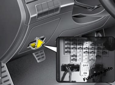
Instrument panel
The fuse box is located on the driver’s side of the instrument panel behind the cover.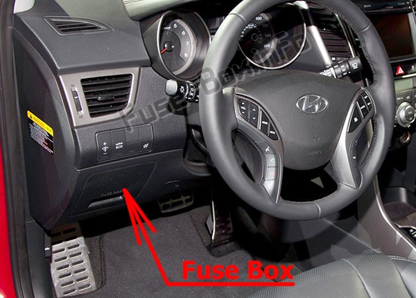
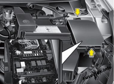
Engine compartment
The fuse box is located in the engine compartment (left-side).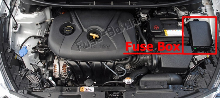
Fuse box diagrams
Fuse box diagrams
2016, 2017
Instrument panel
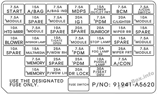
Assignment of the fuses in the instrument panel (2016, 2017)
| Description | Amp rating | Protected component |
|---|---|---|
| C/LIGHTER | 20A | Console Cigar Light, Rear Power Outlet |
| 1 MODULE | 7.5A | Sport Mode Switch |
| 4 MODULE | 7.5A | A/ C Control Module, Head Lamp Leveling Device Actuator LH/RH, Fuel Filter Warning Sensor(D4FD), Rear Parking Assist System |
| 3 MODULE | 7.5A | Instrument Cluster, BCM, Tire Pressure Monitoring Module, Audio, Driver/Passenger Seat Warmer Module, ATM shift lever Ind |
| POWER OUTLET FRT | 15A | Front Power Outlet |
| HTD MIRR | 10A | Driver/Passenger Power Outside Mirror, A/C Control Module, ECU |
| WIPER FRT | 25A | ICM Relay Box (Rain Sensor Relay), Multifunction Switch, E/R Fuse & Relay Box (RLY. 7) Front Wiper Motor |
| A/CON | 7.5A | A/C Control Module, E/R Fuse & Relay Box (RLY. 4) |
| P/WDW LH | 25A | P/WDW LH Relay, Driver Safety Power Window Module (LHD) |
| T/GATE OPEN | 10A | Tail Gate, Rear Camera Open Actuator |
| P/SEAT DRV | 30A | Driver Manual Switch |
| 2 MODULE | 7.5A | ICM Relay Box, Rear Camera Module, Electro Chromic Mirror |
| WIPER RR | 15A | Rear Wiper Relay, Rear Wiper Motor, Multifunction Switch |
| STOP LAMP | 15A | Stop Lamp Switch |
| P/WDW RH | 25A | P/WDW RH Relay, Driver Safety Power Window Module (RHD) |
| 2 PDM | 7.5A | Smart Key Control Module, Start/Stop Button Switch, Ultrasonic Instruction Protection Sensor |
| 5 MODULE | 7.5A | EMS BOX (Head Lamp Washer Relay), Ionizer Unit, Panorama Sunroof, DSL BOX (PTC Relay), E/R Fuse & Relay BOX(RLY.), Driver/Passenger Seat Warmer Module |
| IG1 | 20A | E/R Fuse & Relay Box (Fuse – F) |
| 6 MODULE | 10A | Outside Mirror Switch, Audio, Navigation Head Unit, Digital Clock |
| MDPS | 7.5A | EPS Control Module |
| DR LOCK | 20A | Door Lock/Unlock Relay, ICM Relay BOX (Dead Lock Relay), Driver/Passenger Door Lock Actuator, Fuel filler actuator, Door Lock Actuator LH/RH |
| INTERIOR LAMP | 10A | Vanity Lamp LH/RH, Overhead Console Lamp, Room Lamp, Luggage Lamp, DR Warning Switch |
| MULTI MEDIA | 15A | Audio, Navigation Head Unit |
| A/BAG | 15A | SRS Control Module |
| 1 MEMORY | 7.5A | Instrument Cluster |
| A/BAG IND | 7.5A | Instrument Cluster |
| 3 PDM | 7.5A | Smart Key Control Module, Ultrasonic instrusion Protection Sensor |
| 2 MEMORY | 10A | Outside Mirror Switch, Tire Pressure Monitoring Module, BCM, Auto Light & Photo Sensor, OBD, Digital Clock, A/C Control Module |
| 1 PDM | 25A | Smart Key Control Module |
| START | 7.5A | W/O Button Start: E/R Fuse & Relay Box (RLY.) Ignition Lock Switch, Transaxle Range Switch With Button Start: ECM/PCM, Transaxle Range Switch |
| SUNROOF | 20A | Panorama Sunroof |
| BCM | 7.5A | BCM, Smart Key Control Module |
| A/CON SWITCH | 7.5A | A/C Control Module |
| 7 MODULE | 7.5A | BCM, Smart Key Control Module |
| FOG LAMP RR | 10A | Rear Fog Lamp |
| PUDDLE LAMP | 10A | Driver/Passenger Power Outside Mirror |
Engine compartment
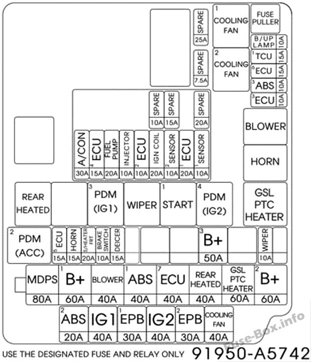
Assignment of the fuses in the Engine compartment (2016, 2017)
| Description | Amp rating | Protected component |
|---|---|---|
| MULTI FUSE: | ||
| MDPS | 80A | EPS Control Module |
| 1B+ | 60A | I/P Junction Box (IPS 0 (4CH), IPS 1 (4CH), IPS 2 (2CH), Fuse – F13/F14/F19/F20/F21 /F26/ F36) |
| 1 ABS | 40A | ESC Control Module, Multipurpose Check Connector |
| BLOWER | 40A | RLY. 4 (Blower Relay) |
| 2B+ | 60A | I/P Junction Box (IPS 3 (4CH), IPS 4 (4CH), Fuse – F2/F7/F9/F15) |
| GSLPTC HEATER | 60A | RLY. 12 (GASOLINE PTC Relay) |
| FUSE: | ||
| COOLING FAN | 40A | RLY 1 (C/FAN LO Relay), RLY 2 (C/FAN HI Relay) |
| 2 ABS | 20A | ESC Control Module, Multipurpose Check Connector |
| IG2 | 40A | RLY 9 (Start Relay), Ignition Switch (W/O Button Start), RLY 6 (PDM 4 (IG2) Relay, With Button Start) |
| IG1 | 40A | W/O Button Start: Ignition Switch, With Button Start: RLY 8 (PDM 2 (ACC) Relay)/RLY. 10 (PDM 3 (IG1) Relay |
| DEICER | 15A | ICM Relay Box (Front Deicer Relay) |
| 3B+ | 50A | I/P Junction Box (Leak Current Autocut Device, Fuse – F18/F25/F30/F34/F38) |
| BRAKE SWITCH | 10A | Smart Key Control Module, Stop Signal Relay |
| S/HEATER FRT | 20A | Driver/Passenger Seat Warmer Module |
| WIPER | 10A | PCM/ECM |
| HORN | 15A | RLY. 5 (Horn Relay), ICM Relay Box (B/A Horn Relay) |
| 1 TCU | 15A | A/T – TCM (D4FD), Transaxle Range Switch |
| 6 ECU | 15A | RLY. 9 (D4FD, Start Relay), ECM/PCM |
| 3 ABS | 10A | ESC Control Module, Multipurpose Check Connector |
| 3 ECU | 10A | ECM/PCM, Air Flow Sensor, Stop Lamp Switch |
| B/UP LAMP | 10A | M/T – Back-Up Lamp Switch, A/T – Rear Combination Lamp (IN) LH/RH, Rear Curtain Module, Navigation Head Unit, Electro Chromic Mirror, IPS Control Module |
| 1 ECU | 20A | G4FD/D4FD : ECM G4NA/G4NC : PCM (A IT), ECM (M/T) |
| IGN COIL | 20A | G4NA : Ignition Coil #1/#2/#3/#4, Condenser |
| 2 SENSOR | 10A | G4FD : Oxygen Sensor (UP/DOWN), Variable Intake Solenoid Valve, Purge Control Solenoid Valve G4NA/G4NC : Oxygen Sensor (UP/DOWN), Variable Intake Solenoid Valve, Purge Control Solenoid Valve D4FD : Camshaft Position Sensor, EGR Cooling Bypass Solenoid Valve, Diesel Box (Glow Relay) |
| 1 SENSOR | 10A | G4FD : Oil Control Valve #1/ #2, Oil Level Sensor, E/R Fuse & Relay Box (RLY. 1) G4NA/G4NC : Oil Control Valve #1/ #2, Camshaft Position Sensor (Intake/Exhaust), E/R Fuse & Relay Box (RLY. 1) D4FD : E/R Fuse & Relay Box (RLY 1), Diesel Box (PTC Heater Relay#1), Lambda Sensor, VGT Control Solenoid Valve |
| 2 ECU | 10A | G4FD : ECM G4NA : Fuel Pump Relay G4NC : Fuel Pump Relay, PCM (A/T), ECM (M/T) D4FD : Oil Level Sensor, Fuel Pressure Regulating Valve |
| INJECTOR | 10A | G4NA – Injector #1/#2/#3/#4 |
| 4 ECU | 15A | G4NA/G4NC : PCM (ATT), ECM (M/T) |
| FUEL PUMP | 20A | EMS Box (Fuel Pump Relay) |
| A/CON | 30A | EMS Box (Air Conditioner) |
| EMS | 40A | EMS Box |
Assignment of the relay
| Description | Protected component | Type |
|---|---|---|
| 1 COOLING FAN | C/FAN LO RELAY | PLUG MICRO |
| 2 COOLING FAN | C/FAN HI RELAY | PLUG MICRO |
| BLOWER | BLOWER RELAY | PLUG MICRO |
| HORN | HORN RELAY | PLUG MICRO |
| 4 PDM (IG2) | PDM 4 (IG2) RELAY | PLUG MICRO |
| WIPER | FRONT WIPER RELAY | PLUG MICRO |
| 1 PDM (ACC) | PDM 1 (ACC) RELAY | PLUG MICRO |
| START 1 | START RELAY | PLUG MICRO |
| 3 PDM (IG1) | PDM 3 (IG1) RELAY | PLUG MICRO |
| REAR HEATED | RR HTD RELAY | PLUG MICRO |
| GSL PTC HEATER | PTC Heater/Fuel Filter | PLUG MINI |


