

See other Hyundai Kona:

Fuse Layout Hyundai Kona EV 2019-..
Contents

Cigar lighter (power outlet) fuse in the Hyundai Kona EV is located in the Instrument panel fuse box (see fuse “POWER OUTLET”).
Table of Contents
Fuse box location
Fuse box location
Instrument panel
The fuse box is located on the driver’s side of the instrument panel behind the cover.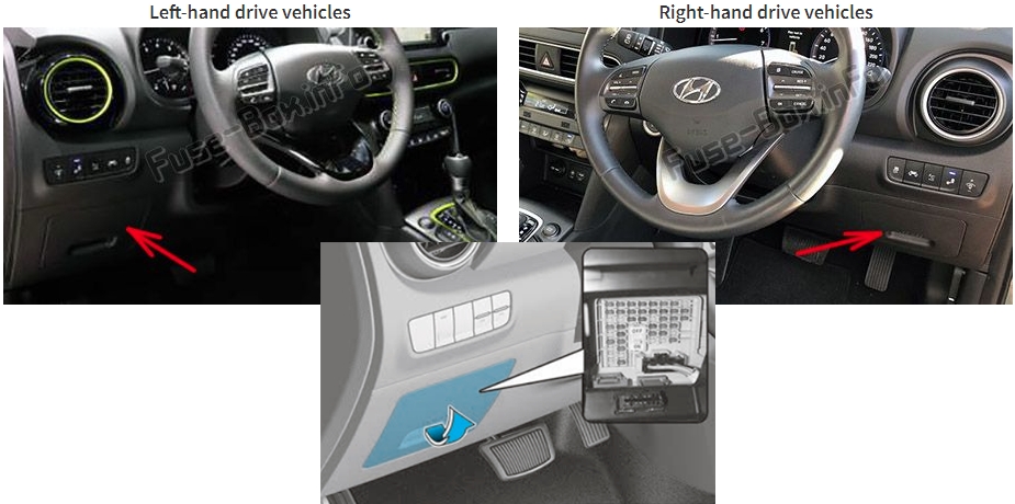
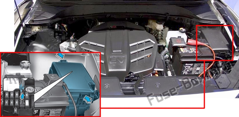
Engine compartment
Fuse box diagrams
Fuse box diagrams
2019
Instrument panel
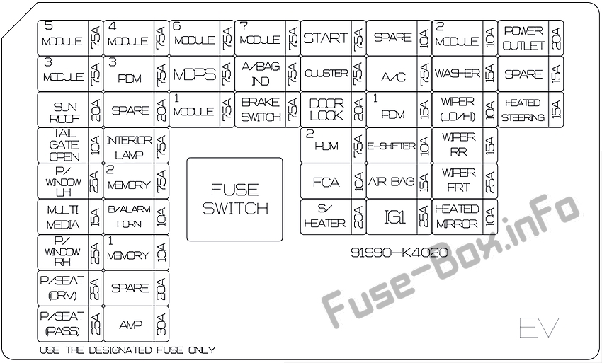
Assignment of the fuses in the instrument panel (2019)
| Fuse Name | Fuse Rating | Protected Component |
|---|---|---|
| MODULE 5 | 7.5A | Electro Chromic Mirror, Audio, A/V & Navigation Head Unit, Crash Pad Switch, Head Lamp LH, Front Air Ventilation Seat Module, Front Seat Warmer Module |
| MODULE 3 | 7.5A | Stop Lamp Switch, BCM |
| SUNROOF | 20A | Sunroof Unit |
| TAIL GATE OPEN | 10A | Tail Gate Relay |
| P/WINDOW LH | 25A | Power Window LH Relay, Driver Safety Power Window Module |
| MULTI MEDIA | 15A | Audio, A/V & Navigation Head Unit |
| P/WINDOW RH | 25A | Power Window RH Relay, Passenger Safety Power Window Module |
| P/SEAT(DRV) | 25A | Driver Seat Manual Switch, Driver Lumbar Support Switch |
| P/SEAT(PASS) | 25A | Passenger Seat Manual Switch |
| MODULE 4 | 7.5A | Blind-Spot Collision Warning Unit LH/RH, BCM, Crash Pad Switch, Vess Unit (Speaker), Multifunction Front View Camera |
| PDM 3 | 7.5A | Smart Key Control Module |
| SPARE | 20A | Spare |
| INTERIOR LAMP | 7.5A | Glove Box Lamp, Vanity Lamp LH/RH, Room Lamp, Overhead Console Lamp, Wiresess Charger Unit, Luggage Lamp |
| MEMORY 2 | 7.5A | Vess Unit (Speaker), Electronic Refrigerant Reduced Pressure Valve |
| B/ALARM HORN | 10A | Not Used |
| MEMORY 1 | 10A | A/C Control Module, Head Up Display, Instrument Cluster, BCM, Rain Sensor |
| SPARE | 20A | Spare |
| AMP | 30A | AMP |
| MODULE 6 | 7.5A | Smart Key Control Module, BCM |
| MDPS | 7.5A | MDPS Unit |
| MODULE 1 | 7.5A | Active Air Flap, Hazard Switch, Data Link Connector, ICM Relay Box (Outside Mirror Folding/Unfolding Relay) |
| MODULE 7 | 7.5A | Front Air Ventilation Seat Module, Front Seat Warmer Module |
| A/BAG IND | 7.5A | Instrument Cluster, A/C Control Module |
| BRAKE SWITCH | 7.5A | Stop Lamp Switch, Smart Key Control Module |
| START | 7.5A | Smart Key Control Module, EPCU |
| CLUSTER | 7.5A | Head Up Display, Instrument Cluster |
| DOOR LOCK | 20A | Door Lock Relay, Door Unlock Relay, ICM Relay Box (Two Turn Unlock Relay) |
| PDM 2 | 7.5A | Start/Stop Button Switch |
| FCA | 10A | Forward Collision Avoidance Assist Unit |
| S/HEATER | 20A | Front Seat Warmer Module, Front Air Ventilation Seat Module |
| SPARE | 20A | Spare |
| A/C | 7.5A | A/C Control Module, Cluster Ionizer |
| PDM 1 | 15A | Smart Key Control Module |
| E-SHIFTER | 10A | Shift Select Switch (SBW), Front Console Switch |
| AIR BAG | 15A | SRS Control Module, Passenger Occupant Detection Sensor |
| IG1 | 25A | PCB Block(FUSE : IEB 3, EPCU 2) |
| MODULE 2 | 10A | Wiresess Charger Unit, Smart Key Control Module, BCM, Audio, A/V & Navigation Head Unit, Power Outlet #1, AMP, Power Outside Mirror Switch |
| WASHER | 15A | Muntifunction Switch |
| WIPER (LO/HI) | 10A | BCM |
| WIPER RR | 15A | Rear Wiper Relay, Rear Wiper Motor |
| WIPER FRT | 25A | Front Wiper Motor, E/R Junction Block (Front Wiper(Low) Relay) |
| HEATED MIRROR | 10A | Driver/Passenger Power Outside Mirror, A/C Control Module |
| POWER OUTLET | 20A | Power Outlet #2 |
| SPARE | 15A | Spare |
| HEATED STEERING | 15A | BCM |
Engine compartment
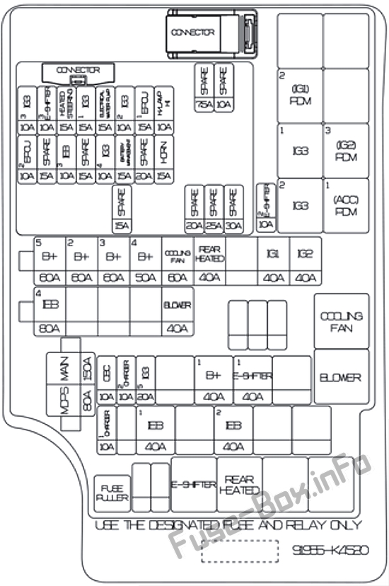
Assignment of the fuses in the Engine compartment (2019)
| Fuse Name | Fuse Rating | Protected Component |
|---|---|---|
| MAIN | 150A | E/R Junction Block (Fuse – IEB 1, IEB 2, CHARGER 1), EPCU (LDC) |
| MDPS | 80A | MDPS Unit |
| B+ 5 | 60A | PCB Block ((Fuse – BATTERY MANAGEMENT, HORN, EPCU 1, H/LAMP), IG3 MAIN Relay) |
| B+ 2 | 60A | IGPM ((Fuse – S/HEATER), IPSO, IPS1, IPS2) |
| B+ 3 | 60A | IGPM (IPS3, IPS5, IPS6, IPS7, IPS8) |
| B+ 4 | 50A | IGPM (Fuse – P/WINDOW LH, P/WINDOW RH, TAIL GATE OPEN, SUNROOF, AMP, P/SEAT (DRV), P/SEAT (PASS)) |
| COOLING FAN | 60A | E/R Junction Block (Cooling Fan Relay) |
| REAR HEATED | 40A | E/R Junction Block (Rear Heated Relay) |
| IG1 | 40A | E/R Junction Block (PDM (IG1) 2 Relay, PDM (ACC) 1 Relay) |
| IG2 | 40A | E/R Junction Block (PDM (IG2) 3 Relay) |
| IEB 4 | 40A | Electronic Brake Control Module |
| BLOWER | 40A | E/R Junction Block (Blower Relay) |
| OBC | 10A | OBC |
| CHARGER 2 | 10A | ICM Relay Box (Charge Lock/Unlock Relay), CCM Unit |
| IG3 5 | 20A | E/R Junction Block (IG3 1 Relay, IG3 2 Relay) |
| B+ 1 | 40A | IGPM ((Fuse – BRAKE SWITCH, MODULE 1, PDM 1, PDM 2, DOOR LOCK), Leak Current Autocut Device) |
| E-SHIFTER 1 | 40A | E/R Junction Block (Fuse – E-SHIFTER, E-Shifter Relay) |
| CHARGER 1 | 10A | Charge Connector Door Module |
| IEB 1 | 40A | Electronic Brake Control Module, Multipurpose Check Connector |
| IEB 2 | 40A | Electronic Brake Control Module |
| IG3 3 | 10A | E/R Junction Block (Cooling Fan Relay, Blower Relay), Electronic A/C Compressor, 3Way Coolant Control Valve LH/RH |
| E-SHIFTER 3 | 10A | SCU |
| IG3 1 | 15A | E/R Junction Block (IG3 1 Relay, IG3 2 Relay) |
| ELECTRICAL WATER PUMP | 15A | Electronic Water Pump |
| IG3 2 | 10A | BMU, OBC, EPCU |
| EPCU 1 | 15A | EPCU |
| H/LAMP HI | 10A | Head Lamp (High) Relay |
| EPCU 2 | 10A | EPCU |
| IEB 3 | 10A | Electronic Brake Control Module, Multipurpose Check Connector |
| IG3 4 | 10A | Active Air Flap, CCM Unit, Charge Connector Door Module, Air Conditioning PTC Heater, Crash Pad Switch, A/C Control Module, Audio, A/V & Navigation Head Unit, Instrument Cluster, IPGM (IPS Control Module) |
| BATTERY MANAGEMENT | 15A | BMU |
| HORN | 15A | Horn Relay |


