


Fuse Layout KIA Sportage 2011-2016
Contents

Cigar lighter (power outlet) fuses in the KIA Sportage are located in the Instrument panel fuse box (see fuses “POWER OUTLET 2” (Rear Power Outlet, Front Left Power Outlet, Front Cigarette Lighter), “POWER OUTLET 1” (Front Right Power Outlet)).
Table of Contents
Fuse box location
Fuse box location
Instrument panel
The fuse box is located behind the cover on the driver’s side of the instrument panel.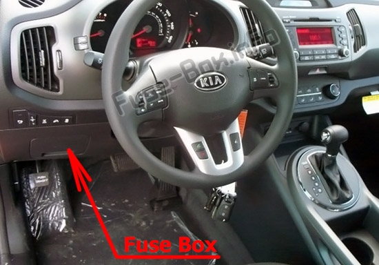
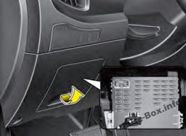
Left-hand drive vehicles
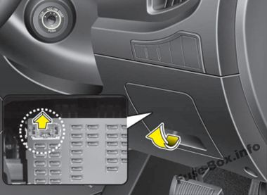
Right-hand drive vehicles
Engine compartment
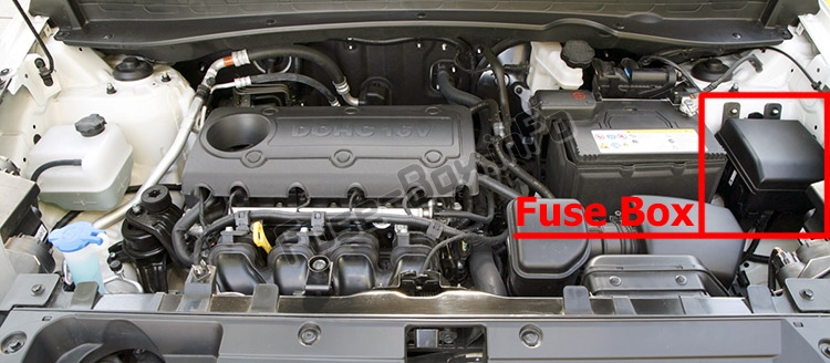
Additional fuse box (if equipped)
It is located near the main fuse box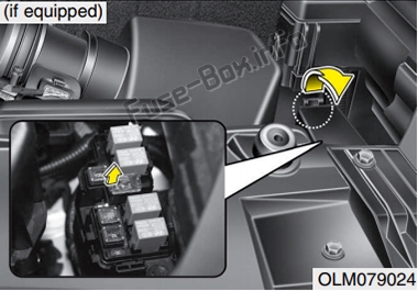
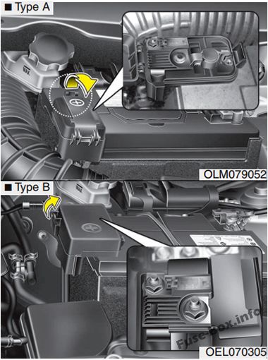
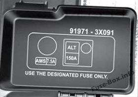
Main fuse
Fuse box diagrams
Fuse box diagrams
2011, 2012, 2013, 2014, 2015
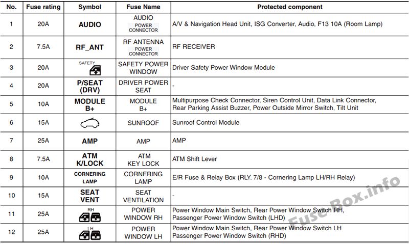
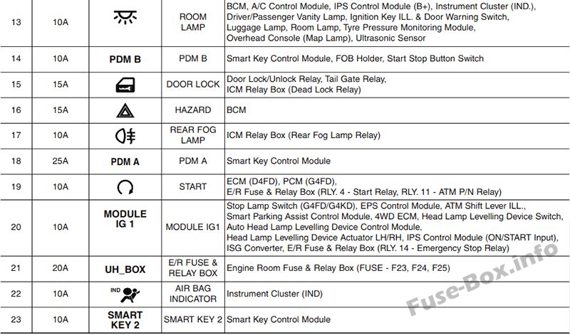
Instrument panel
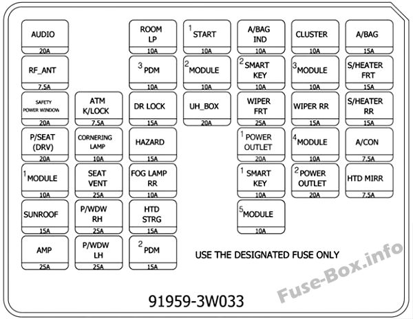
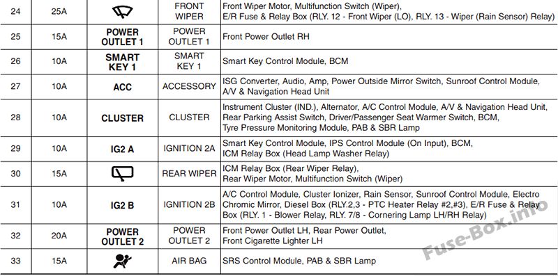
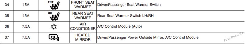
Assignment of the fuses in the Instrument panel (2011-2015)
| Name | Amp rating | Protected component |
|---|---|---|
| POWER CONNECTOR (AUDIO) | 20A | Audio |
| POWER CONNECTOR (RFANT) | 7.5A | RF Receiver |
| A/BAG | 15A | SRS Control Module, Passenger Occupant Detection Sensor, Telltale & SBR Lamp |
| S/HEATER FRT | 15A | Driver/Passenger Seat Warmer Switch |
| S/HEATER RR | 15A | Rear Seat Warmer LH/RH |
| A/CON | 7.5A | A/C Control Module (Auto) |
| HTD MIRR | 7.5A | A/C Control Module, Driver/Passenger Power Outside Mirror |
| CLUSTER | 10A | Driver/Passenger Seat Warmer Switch, Driver CCS Control Module, Instrument Cluster, Tire Pressure Monitoring Module, Audio, Alternator, BCM, A/C Control Module, Telltale & SBR Lamp |
| IG2 A | 10A | BCM, Smart Key Control Module, IPS Control Module (IG2) |
| WIPER RR | 15A | Rear Wiper Motor, Multifunction Switch (Wiper), ICM Relay Box (Rear Wiper Relay) |
| IG2 B | 10A | Cluster Ionizer, A/C Control Module, Rain Sensor, Sunroof Motor, Electro Chromic Mirror, E/R Fuse & Relay Box (Blower Relay) |
| POWER OUTLET 2 | 20A | Rear Power Outlet, Front Power Outlet LH, Front Cigarette Lighter |
| A/BAG IND | 10A | Instrument Cluster (A/Bag IND.) |
| SMART KEY 2 | 10A | Smart Key Control Module |
| WIPER FRT | 25A | Front Wiper Motor, Multifunction Switch (Wiper), E/R Fuse & Relay Box (Front Wiper (Low) Relay, Wiper (Rain Sensor) Relay) |
| POWER OUTLET 1 | 15A | Front Power Outlet RH |
| SMART KEY 1 | 10A | BCM, Smart Key Control Module |
| ACC | 10A | Audio, Amp, Sunroof Control Module, Power Outside Mirror Switch |
| START | 10A | Burglar Alarm Relay (With Burglar Alarm), E/R Fuse & Relay Box (Start Relay : W/O Burglar Alarm & Smart Key), Smart Key Control Module (W/O Burglar Alarm & With Smart Key) |
| MODULE IG1 | 10A | EPS Control Module, ATM Shift Lever ILL., 4WD ECM, Stop Lamp Switch, IPS Control Module (IG1) |
| UHBOX | 20A | E/R Fuse & Relay Box (ECU 2 7.5A, ABS 7.5A, TCU 2 7.5A) |
| ROOM LP | 10A | BCM, Map Lamp, Room Lamp, Driver/Passenger Vanity Lamp, Electro Chromic Mirror, Luggage Lamp, Ignition Key ILL. & Door Warning Switch, Tire Pressure Monitoring Module, Instrument Cluster (MCU, IND.), A/C Control Module, IPS Control Module (B+) |
| PDM B | 10A | Start/Stop Button Switch, Smart Key Control Module |
| DR LOCK | 15A | Door Lock Relay, Door Unlock Relay, Tail Gate Relay, ICM Relay Box (Two Turn Unlock Relay) |
| HAZARD | 15A | BCM |
| FOG LP RR | 10A | (Not Used) |
| PDM A | 25A | Smart Key Control Module |
| ATM K/LOCK | 7.5A | ATM Shift Lever, Key Solenoid |
| CORNERING LAMP | 10A | (Not Used) |
| SEAT VENT | 15A | Driver CCS Seat Warmer |
| P/WDW RH | 25A | Power Window Main Switch, Passenger Power Window Switch, Rear Power Window Switch RH |
| P/WDW LH | 25A | Rear Power Window Switch LH, Power Window Main Switch |
| SAFETY POWER WINDOW | 20A | Driver Safety Power Window Module |
| P/SEAT(DRV) | 20A | Driver Seat Manual Switch |
| MODULE B+ | 10A | Multipurpose Check Connector, Data Link Connector, Driver CCS Switch, Rear Parking Assist Buzzer |
| SUNROOF | 15A | Sunroof Motor, Sunroof Control Module |
| AMP | 25A | Amp |
| HTD_STRG | 15A | Heated steering wheel |
Engine compartment
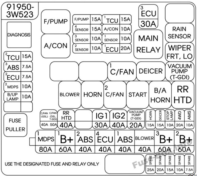
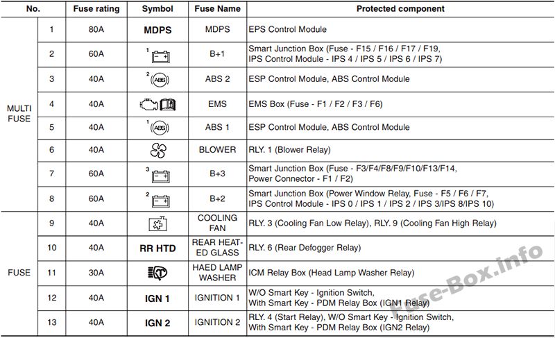
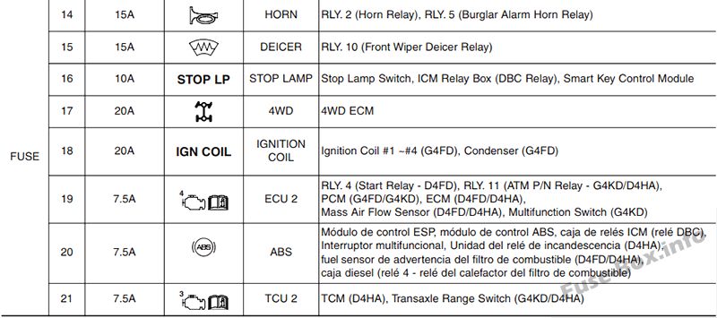
Assignment of the fuses in the Engine compartment (2011-2015)
| Name | Amp rating | Protected component |
|---|---|---|
| MULTI FUSES: | ||
| MDPS | 80A | EPS Control Module |
| B+1 | 60A | I/P Junction Box (PDM A 25A, DR LOCK 15A, HAZARD 15A, IPS 4-7) |
| ABS 2 | 40A | ESC Module |
| EMS | 40A | EMS Box (TCU 1 15A, ECU 30A, A/CON 10A, F/PUMP 15A) |
| ABS 1 | 40A | ESC Module |
| BLOWER | 40A | Blower Relay |
| B+3 | 60A | I/P Junction Box (P/SEAT(DRV) 20A, SAFETY POWER WINDOW 20A, PDM B 10A, ATM K/LOCK 7.5A, SEAT VENT 15A, Power Connector (AUDIO 20A, RF ANT 7.5A), ROOM LP 10A) |
| B+2 | 60A | I/P Junction Box (Power Window Relay, SUNROOF 15A, AMP 25A, MODULE B+ 10A, IPS 0-3, IPS 8-10) |
| FUSES: | ||
| C/FAN (MPI engine) | 40A | Cooling Fan (High) Relay, Cooling Fan (Low) Relay |
| C/FAN (T-GDI engine) | 50A | Cooling Fan (High) Relay, Cooling Fan (Low) Relay |
| RR HTD | 40A | Rear Defogger Relay |
| IG 1 | 30A | PDM Relay Box (IGN1/ACC Relay : With Smart Key), Ignition Switch (W/O Smart Key) |
| IG 2 | 40A | PDM Relay Box (IGN2 Relay : With Smart Key), Ignition Switch (W/O Smart Key) |
| HORN | 15A | Horn Relay |
| DEICER | 15A | Front Wiper Deicer Relay |
| STOP LP | 10A | Stop Lamp Switch, Smart Key Control Module, ICM Relay Box (DBC Relay) |
| 4WD | 20A | 4WD ECU |
| AMS | 10A | Battery Sensor |
| TCU 2 (MPI engine) | 7.5A | Transaxle Range Switch |
| TCU 2 (T-GDI engine) | 7.5A | Transaxle Range Switch, Vacuum Switch, Vacuum Pump Relay |
| ABS | 7.5A | ESC Module, ICM Relay Box (DBC Relay), Multi Switch |
| ECU 2 | 7.5A | ATM P/N Relay, PCM, Multifunction Switch (Remote Control) |
| V_PUMP (T-GDI engine) | 20A | Vacuum Pump Relay |
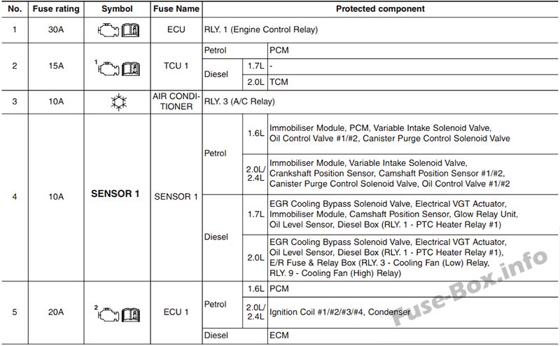
Engine compartment main fuse panel (EMS Box) (2011-2015)
| Name | Amp rating | Protected component |
|---|---|---|
| F/PUMP | 15A | Fuel Pump Relay |
| SENSOR 4 | 15A | Fuel Pump Relay, PCM, Oxygen Sensor (Up)/(Down), E/R Fuse & Relay Box (Cooling Fan (High)/(Low) Relay) |
| SENSOR 3 | 10A | A/CON Relay, Injector #1~#4 |
| SENSOR 2 | 10A | (Not Used) |
| TCU 1 | 15A | PCM |
| A/CON | 10A | A/CON Relay |
| SENSOR 1 (MPI engine) | 10A | Immobilizer Module, Crankshaft Position Sensor, Camshaft Position Sensor #1/#2, Oil Control Valve #1/#2Canister Purge Control Solenoid Valve, Variable Intake Solenoid Valve, Canister Close Valve |
| SENSOR 1 (T-GDI engine) | 10A | Immobilizer Module, Crankshaft Position Sensor, Camshaft Position Sensor #1/#2, Oil Control Valve #1/#2Canister Purge Control Solenoid Valve, Variable Intake Solenoid Valve, Canister Close Valve, RCV |
| ECU 1 | 20A | Ignition Coil #1~#4, Condenser |
| ECU | 30A | Engine Control Relay |
Battery fuse terminal
Version 1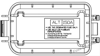
Version 2
2011, 2012, 2013, 2014, 2015 RHD (UK)
Assignment of the fuses in the Instrument panel (2011-2015 RHD)
Assignment of the fuses in the engine compartment (2011-2015 RHD)
Engine compartment main fuse panel (EMS Box) (2011-2015 RHD)
Battery fuse terminal
Version 1
Version 2


