

See other KIA Optima:


Fuse Layout KIA Optima 2011-2015
Contents

Cigar lighter (power outlet) fuse in the KIA Optima are located in the Instrument panel fuse box (see fuses “POWER OUTLET” (Front Power Outlet) and “C/LIGHTER” (Cigar Lighter)).
Table of Contents
Fuse box location
Fuse box location
Instrument panel
The fuse box is located behind the cover to the left of the steering wheel.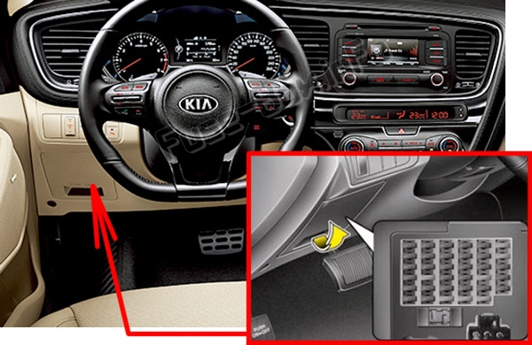
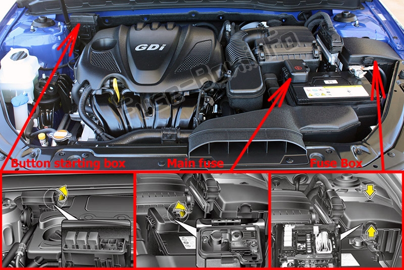
Engine compartment

Fuse box diagrams
Fuse box diagrams
2011, 2012, 2013
Assignment of the fuses in the Instrument panel (2011, 2012, 2013)
| Name | Amp rating | Circuit Protected |
|---|---|---|
| MODULE 3 | 7.5A | Key Solenoid, Sport Mode Switch |
| PDM 1 | 25A | Smart Key Control Module |
| POWER OUTLET | 15A | Front Power Outlet |
| MODULE 5 | 7.5A | Smart Key Control Module, Rear Seat Warmer Relay LH/RH |
| MODULE 2 | 7.5A | BCM, Panorama Sunroof, Rain Sensor |
| TRUNK | 10A | I/P Junction Box (Trunk Relay), Fuel Filler Door & Trunk Lid Switch, Trunk Room LP |
| CLOCK | 10A | A/V & Navigation Head Unit, Audio, Smart Key Control Module, Overhead Console Lamp, Crash Pad Mood Lamp, A/C Control Module, BCM, AMP, Power Outside Mirror Switch, Driver/Passenger Door Mood Lamp |
| C/LIGHTER | 15A | Cigar Lighter |
| HTD STRG | 15A | Steering Wheel Heater |
| A/CON | 7.5A | A/C Control Module, E/R Fuse & Relay Box (Blower Relay) |
| WIPER | 25A | Multifunction Switch, Front Wiper Motor, E/R Fuse & Relay Box (Wiper Relay, Rain SNSR Relay) |
| S/HEATER FRT | 20A | Driver/Passenger CCS Cushion Warmer, Driver/Passenger Seat Warmer Module |
| MIRR HTD | 10A | Driver/Passenger Power Outside Mirror |
| MODULE 4 | 7.5A | Front Seat Warmer & CCS Switch, Driver/Passenger CCS Control Module, Driver/Passenger Seat Warmer Module, Tire Pressure Monitoring Module, Audio |
| A/BAG IND | 7.5A | Instrument Cluster (Air Bag IND.) |
| START | 7.5A | W/O Smart Key : Burglar Alarm Relay With Smart Key : PCM, Transaxle Range Switch |
| S/HEATER RR | 15A | Rear Seat Warmer Relay LH/RH |
| P/SEAT PASS | 20A | Passenger Seat Manual Switch |
| FOG LP RR | 15A | – |
| MODULE 1 | 7.5A | Head Lamp Leveling Device Actuator LH/RH, Auto Head Lamp Leveling Device Module, Driver IMS Module, ATM Lever Indicator, BCM, A/C Control Module, Electro Chromic Mirror, Lane Keeping Assist Module, Instrument Cluster |
| VACCUM | 20A | Vacuum Pump, Vacuum Switch |
| A/BAG | 15A | Telltale Lamp, SRS Control Module, Passenger Weight Classification Sensor |
| P/WDW LH | 25A | I/P Junction Box (Power Window LH Relay), Driver/Passenger Power Window Safety Module |
| AMP | 30A | AMP |
| PDM 2 | 7.5A | Start Stop Button Switch, Smart Key Control Module, Fob Holder |
| MDPS | 10A | EPS Control Module, Crash Pad Switch |
| PDM 3 | 7.5A | Smart Key Control Module |
| P/WDW RH | 25A | I/P Junction Box (Power Window RH Relay) |
| P/SEAT DRV | 30A | Driver IMS Module, Driver Seat Manual Switch, Driver Lumbar Support Switch |
| DR LOCK | 20A | Two Turn Unlock Relay, I/P Junction Box (Door Lock Relay, Door Unlock Relay, Turn Signal Lamp Sound Relay) |
| SUNROOF | 20A | Panorama Sunroof |
| IG 1 | 20A | E/R Fuse & Relay Box (Fuse : ABS 3 10A, TCU 2 15A, ECU 4 10A) |
| POWER CONNECTOR (AUDIO) | 15A | A/V & Navigation Head Unit, Audio |
| POWER CONNECTOR (ROOM LP) | 10A | Driver/Passenger Smart Key Outside Handle, Driver IMS Module, Lamp Auto Cut Relay, Driver/Passenger Door Scuff Lamp, Ignition Key ILL. & Door Warning Switch, A/C Control Module, Data Link Connector, RF Receiver, BCM, Electro Chromic Mirror, Instrument Cluster, Auto Light & Photo Sensor, Tire Pressure Monitoring Module |
Assignment of the fuses in the Engine compartment (2011, 2012, 2013)
| Name | Amp rating | Circuit Protected |
|---|---|---|
| MULTI FUSES: | ||
| IP B+ 2 | 60A | I/P Junction Box (P/SEAT DRV 30A, P/SEAT PASS 20A, AMP 30A, PDM 2 7.5A, IPS 5, IPS 6, ARISU 2) |
| B+ 4 (Not Used) | 60A | – |
| IGN 2 | 40A | E/R Fuse & Relay Box (Start Relay), Fuse & Relay Box (PDM 3(IG 2) Relay), Ignition Switch |
| ABS 1 | 40A | ESC Module |
| RR HTD (G4KJ)/ C/FAN HI (G4KH) | 40A/60A | E/R Fuse & Relay Box (RR HTD Relay) (G4KJ) C/FAN (HI) Relay (G4KH) |
| BLOWER | 40A | E/R Fuse & Relay Box (Blower Relay) |
| IP B+ 1 | 60A | I/P Junction Box (PDM 1 25A, MODULE 3 7.5A, S/HEATER FRT 20A, S/HEATER RR 15A TRUNK 10A, P/WDW LH 25A, P/WDW RH 25A), Power Connector (AUDIO 15A)) |
| MDPS | 80A | EPS Control Module |
| FUSES: | ||
| WIPER | 10A | PCM |
| RR HTD IND | 10A | A/C Control Module |
| AMS | 10A | Battery Sensor |
| TCU 1 | 10A | PCM |
| STOP LP | 10A | E/R Fuse & Relay Box (HAC Relay), Smart Key Control Module, Stop Lamp Switch |
| DEICER | 10A | E/R Fuse & Relay Box (Deicer Relay) |
| H/LP WASHER | 10A | – |
| LDC 1 | 30A | – |
| C/FAN | 40A | E/R Fuse & Relay Box (C/Fan(HI) Relay, C/Fan(LO) Relay) |
| ABS 2 | 30A | Multipurpose Check Connector, ESC Module |
| LDC 2 | 30A | – |
| CVVL(Not Used)/ RR THD (G4KH) | 40A | RR HTD Relay (G4KH) |
| IPB+3 | 50A | I/P Junction Box (Power Connector (ROOM LP 10A), SUNROOF 20A, DR LOCK 20A IPS 1, IPS 3, ARISU 1) |
| IGN 1 | 40A | Fuse & Relay Box (PDM 1(ACC) Relay, PDM 2(IG 1) Relay), Ignition Switch |
| EMS | 40A | EMS Box (HORN 15A, ECU 3 10A, ECU 1 30A, F/PUMP 20A) |
| ECU 4 | 10A | PCM |
| TCU 2 | 15A | Back-Up Lamp Switch, Vehicle Speed Sensor, Transaxle Range Switch |
| ABS 3 | 10A | E/R Fuse & Relay Box (HAC Relay), Stop Lamp Switch, ESC Module, Multipurpose Check Connector |
| B/UP LP | 10A | A/V & Navigation Head Unit, Audio, Electro Chromic Mirror, BCM, Rear Combination Lamp(ln) LH/RH |
| A/CON | 10A | A/C Control Module |
Engine compartment fuse panel (EMS BOX) (2011, 2012, 2013)
| Name | Amp rating | Circuit Protected |
|---|---|---|
| HORN | 15A | EMS Box (Horn Relay), E/R Fuse & Relay Box (B/Horn Relay) |
| F/PUMP | 20A | EMS Box (F/Pump Relay) |
| ECU 3 | 15A | PCM |
| SNSR 1 | 15A | Oxygen Sensor (Up/Down), E/R Fuse & Relay Box (C/FAN (HI/LO) Relay) |
| INJECTOR | 10A | EMS Box (F/Pump Relay) |
| SNSR 3 | 10A | Camshaft Position Sensor #1, #2, Immobilizer Module |
| SNSR 2 | 10A | RCV Control Solenoid Valve(G4KH), Variable Intake Solenoid Valve(G4KJ), Canister Close Valve Oil Control Valve #1, #2, Purge Control Solenoid Valve, Crankshaft Position Sensor |
| IGN COIL | 20A | Condenser, Ignition Coil #1, #2, #3, #4 |
| ECU 1 | 30A | EMS Box (Engine Control Relay) |
2014, 2015
Instrument panel
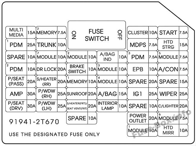
Assignment of the fuses in the Instrument panel (2014, 2015)
| Description | Amp Rating | Protected Component |
|---|---|---|
| MULTIMEDIA | 15A | ISG LDC AUDIO,AUDIO_UVO, AUDIO(PA30A,B), NAVI1.5, NAVI_3.0, NAVI_4.0, TMU |
| PDM 1 | 25A | Smart Key Control Module (With Smart Key) |
| SPARE | 10A | – |
| PDM2 | 10A | SMK UNIT, BUTTON START SW |
| P/SEAT(PASS) | 20A | Passenger Seat Manual Switch |
| AMP | 30A | AMP |
| P/SEAT(DRV) | 30A | Driver IMS Module, Driver Seat Manual Switch, Driver Lumbar Support Switch (2WAY) |
| MEMORY 2 | 7.5A | PIC_RF_RECEIVER |
| TRUNK | 10A | Trunk Lid Relay, Trunk Room Lamp |
| MODULE 7 | 10A | SPORT_MODE_SW, RR POWER WINDOW SW |
| DR LOCK | 20A | Door Lock/Unlock Relay, Dead Lock Relay (RHD), Turn Signal Lamp Sound Relay |
| S/HEATER(RR) | 20A | Rear Seat Warmer Relay LH/RH |
| P/WDW(RH) | 25A | Driver Safety Power Window Module (RHD), Passenger Safety Power Window Module (LHD), Rear Safety Power Window Module RH, Power Window RH Relay |
| P/WDW(LH) | 25A | Driver Safety Power Window Module (LHD), Passenger Safety Power Window Module (RHD), Rear Safety Power, Window Module LH, Power Window LH Relay |
| MODULE 2 | 10A | BCM, Panorama Sunroof, Rain Sensor |
| BRAKE SWITCH | 10A | Smart Key Control Module, Start Stop Button Switch, FOB Holder, Stop Lamp Switch |
| MEMORY 1 | 10A | SEAT EXTN (IMS), DR_TRIM_EXTN (FOLD’G), CLUSTER, A/CON, ECM, AUTO FOLDING RLY, TPMS, POWER OUTLET, A_L_PHOTO_SNSR, MUT |
| SUNROOF | 20A | Panorama Sunroof |
| S/HEATER(FRT) SEAT VERNT(FRT) | 20A | SEAT_EXTN (HEATA/ENT) |
| SPARE | 10A | – |
| A/BAG IND | 10A | Instrument Cluster |
| MODULE 3 | 10A | Sport Mode Switch, Key Solenoid (W/O Smart Key) |
| MODULE 4 | 10A | Driver/Passenger CCS Control Module (With CCS), Driver/Passenger Seat Warmer Module (W/O CCS), Front Seat Warmer & CCS Switch, Oil Pump Inverter, ISG Low DC-DC Converter, Tire Pressure Monitoring Module |
| A/BAG | 15A | A/BAG UNIT IG1 , WCS_PASS IG1 |
| INTERIOR LAMP | 10A | Driver/Passenger Smart Key Outside Handle (With Smart Key), Driver/Passenger Door Lamp, A/C Control Module, Ignition Key ILL. & Door Warning Switch (W/O Smart Key), RF Receiver (With Smart Key), Driver IMS Module, BCM, Data Link Connector, Driver/Passenger Door Scuff Lamp, Power Outside Mirror Switch, Auto Light & Photo Sensor (W/O B/Alarm), Lamp Auto Cut Relay, Instrument Cluster |
| CLUSTER | 10A | CLUSTER (IGN1) |
| MDPS | 7.5A | Crash Pad Switch, EPS Control Module (With MDPS), Steering Angle Sensor (W/O MDPS), ATM Lever Indicator, EPB Switch, EPB Control Module |
| PDM 3 | 7.5A | Smart Key Control Module (With Smart Key) |
| EPB | 10A | EPB |
| SPARE | 20A | – |
| IG 1 | 25A | E/R BOX IG1 |
| SPARE | 10A | – |
| POWER OUTLET | 20A | Front Power Outlet |
| MODULE 1 | 10A | Auto Head Lamp Leveling Device Module (Auto HLLD), Head Lamp Leveling Device Switch (Manual HLLD), Head Lamp Leveling Device Actuator LH/RH, BCM, Front Smart Parking Assist Sensor Module, Instrument Cluster, Electro Chromic Mirror, A/C Control Module, Driver IMS Module, Rear Parking Assist Buzzer, Lane Keeping Assist Module |
| START | 7.5A | B/ALARM RLY |
| HTD STRG | 15A | Steering Wheel Heater |
| MODULE 5 | 7.5A | Smart Key Control Module (With Smart Key), Rear Seat, Warmer Relay LH/RH, E/R Fuse & Relay Box (RLY.2), Diesel Box (Fuel Filter Relay) |
| A/CON | 7.5A | A/C Control Module, E/R Fuse & Relay Box (RLY 14) |
| SPARE | 15A | – |
| WIPER | 25A | E/R BOX WIPER RLY |
| C/LIGHTER | 20A | Cigarette Lighter |
| MODULE 6 | 7.5A | PANORAMA SUNROOF (IG2), IONIZER, DSL_BOX, RR_SEAT_WARMER |
| HTD MIRR | 10A | Driver/Passenger Power Outside Mirror |
Fuse box diagram for Theta 2.4 GDI (Engine compartment)
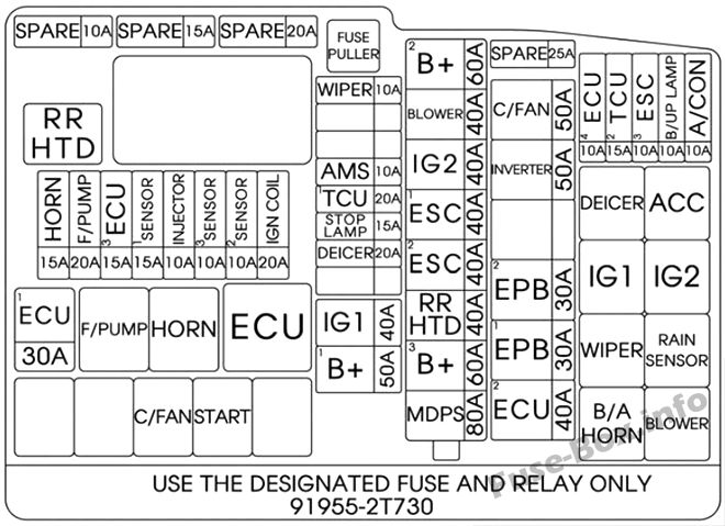
Assignment of the fuses in the Engine compartment Theta 2.4 GDI (2014, 2015)
| Description | Amp Rating | Protected Component |
|---|---|---|
| RR HTD | 40A | E/R BOX RR HTD RLY COIL |
| HORN | 15A | HORN (LH. RH) |
| F/PUMP | 20A | FUEL PUMP MTR |
| ECU 3 | 15A | PCU (GDI) BATT. DIRECT |
| SENSOR 1 | 15A | DN 02 SENSOR (GDI), UP 02 SENSOR (GDI) |
| INJECTOR | 10A | E/R BOX F/PUMP RLY COIL |
| SENSOR 3 | 10A | CMP1, 2 (GDI, TGDI), SMATRA IMMOBILIZER |
| SENSOR 2 | 10A | CKP (GDI), VIS (GDI), OCV1, 2 (GDI), PCSV (GDI), CCV (GDI) |
| IGN COIL | 20A | ENGINE IG COIL |
| ECU 1 | 30A | ECU RLY |
| SPARE | 10A | – |
| SPARE | 15A | – |
| SPARE | 20A | – |
| WIPER | 10A | BCM, RAIN SNSR, WIPER MTR |
| AMS | 10A | BATTERY SENSOR |
| TCU 1 | 20A | TCU |
| STOP LAMP | 15A | RLY.10 (HAC Relay), STOP LAMP RELAY |
| DEICER | 20A | RLY.7 (Deicer Relay) |
| IG1 | 40A | IGN SW |
| B+ 1 | 50A | B+ |
| B+ 2 | 60A | B+ |
| BLOWER | 40A | RLY.14 (Blower Relay) |
| IG 2 | 40A | IGN SW, IG2 RLY |
| ESC 1 | 40A | ESC UNIT MOTOR B+, DIAGNOSIS ABS A/B VALVE B+ |
| ESC 2 | 40A | ESC UNIT SOLENOID B+ |
| RR HTD | 40A | RLY.1 (RR HTD Relay) |
| B+ 3 | 60A | B+ |
| MDPS | 80A | EPS Control Module |
| SPARE | 25A | – |
| C/FAN | 50A | E/R BOX C/FAN 1 RLY SWITCH |
| INVERTER | 50A | O_P_INVERTER |
| EPB 2 | 30A | EPB UNIT BATT2 |
| EPB 1 | 30A | EPB UNIT BATT1 |
| ECU 2 | 40A | EMS BOX (B+) |
| ECU 4 | 10A | ENGINE ECU |
| TCU 2 | 15A | SPEED SNSR, POSITION SW. O_P_INVERTER |
| ESC 3 | 10A | ESC UNIT IGN1 |
| B/UP LAMP | 10A | ELECTRO CHROMIC MIRROR, BCM, REAR COMBINATION LAMP (IN) LH/RH |
| A/CON | 10A | A/C CONTROL MODULE (Auto A/C) |
Fuse box diagram for Theta 2.0 T-GDI (Engine compartment)
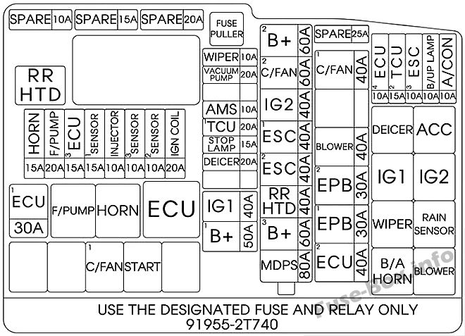
Assignment of the fuses in the Engine compartment (Theta 2.0 T-GDI) (2014, 2015)
| Description | Amp Rating | Protected Component |
|---|---|---|
| RR HTD | – | E/R BOX RR HTD RLY COIL |
| HORN | 15A | HORN (LH. RH) |
| F/PUMP | 20A | FUEL PUMP MTR |
| ECU 3 | 15A | PCU (TGDI) BATT. DIRECT |
| SENSOR 1 | 15A | DN O2 SENSOR (TGDI), UP O2 SENSOR (TGDI), COOLING FAN RLY COIL (TGDI) |
| INJECTOR | 10A | E/R BOX F/PUMP RLY COIL |
| SENSOR 3 | 10A | CMP1, 2 (TGDI), SMATRA IMMOBILIZER |
| SENSOR 2 | 10A | CKP (TGDI), VIS (GDI), OCV1, 2 (TGDI), PCSV (TGDI), RCV (TGDI) |
| IGN COIL | 20A | ENGINE IG COIL |
| ECU 1 | 30A | ECU RLY |
| SPARE | 10A | – |
| SPARE | 15A | – |
| SPARE | 20A | – |
| WIPER | 10A | BCM, RAIN SNSR, WIPER MTR |
| VACUUM PUMP | 20A | BRAKE VACUUM PUMP IG1 |
| AMS | 10A | BATTERY SENSOR |
| TCU 1 | 20A | TCU |
| STOP LAMP | 15A | RLY.10 (HAC Relay), STOP LAMP RELAY |
| DEICER | 20A | RLY.7 (Deicer Relay) |
| IG1 | 40A | IGN SW |
| B+ 1 | 50A | B+ |
| B+ 2 | 60A | B+ |
| C/ FAN 2 | 60A | C/FAN RLY |
| IG 2 | 40A | IGN SW, IG2 RLY |
| ESC 1 | 40A | ESC UNIT MOTOR B+ , DIAGNOSIS ABS A/B VALVE B+ |
| ESC 2 | 40A | ESC UNIT SOLENOID B+ |
| RR HTD | 40A | RLY.1 (RR HTD Relay) |
| B+ 3 | 60A | B+ |
| MDPS | 80A | EPS CONTROL MODULE |
| SPARE | 25A | – |
| C/FAN 1 | 50A | COOLING FAN RLY TGDI |
| BLOWER | 40A | E/R BOX BLOWER RLY SWITCH |
| EPB 2 | 30A | EPB UNIT BATT2 |
| EPB 1 | 30A | EPB UNIT BATT1 |
| ECU 2 | 40A | EMS BOX (B+) |
| ECU 4 | 10A | ENGINE ECU |
| TCU 2 | 15A | SPEED SNSR, POSITION SW. O_P_INVERTER |
| ESC 3 | 10A | ESC UNIT IGN1 |
| B/UP LAMP | 10A | ELECTRO CHROMIC MIRROR, BCM, REAR COMBINATION LAMP (IN) LH/RH |
| A/CON | 10A | A/C CONTROL MODULE (Auto A/C) |
Battery terminal cover (Main fuse)


