

See other KIA Cee’d:

Fuse Layout KIA Ceed 2007-2012
Contents

Cigar lighter (power outlet) fuses in the KIA Cee’d are located in the Instrument panel fuse box (see fuses “C/LIGHTER” (Cigar lighter), “P/OUTLET” (Power outlet) and “RR P/OUTLET” (Rear power outlet)).
Table of Contents
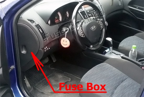
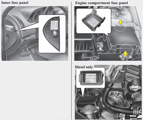
Fuse box location
Fuse box location
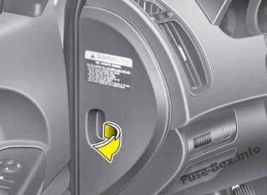
Instrument panel
Left-hand drive vehicles
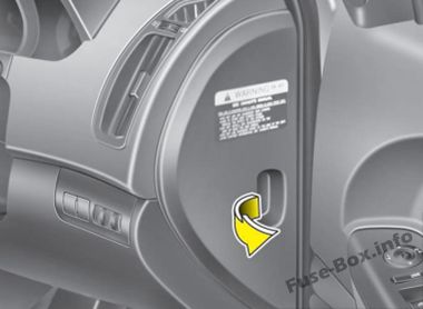
Right-hand drive vehicles
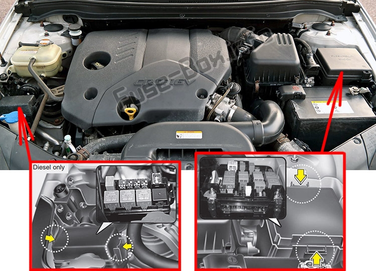
Engine compartment
Assignment of the fuses in the Instrument panel
Assignment of the fuses in the Instrument panel
| Description | Amp rating | Protected component |
|---|---|---|
| START | 10A | Start motor solenoid |
| A/CON SW | 10A | Air-conditioning system |
| HTD MIRR | 10A | Outside review mirror defroster |
| SEAT HTR | 15A | Seat warmer |
| A/CON | 10A | Air-conditioning system |
| HEAD LAMP | 10A | Headlight |
| FR WIPER | 25A | Wiper (front) |
| RR WIPER | 15A | Rear wiper |
| DRL OFF | – | Daytime running light off |
| RR FOG | 10A | Fog light (rear) |
| P/WDW (LH) | 25A | Power window (left) |
| CLOCK | 10A | Clock |
| C/LIGHTER | 15A | Cigar lighter |
| DR LOCK | 20A | Sunroof, Door lock/unlock |
| DEICER | 15A | Front deicer |
| STOP | 15A | Stop lamp switch |
| ROOM LP | 15A | Room lamp |
| AUDIO | 15A | Audio, Trip Computer |
| T/LID | 15A | Tailgate, Folding mirror |
| SAFETY P/WDW RH | 25A | Safety power window (right) |
| SAFETY P/WDW LH | 25A | Safety power window (left) |
| P/WDW(RH) | 25A | Power window (right) |
| P/OUTLET | 15A | Power outlet |
| T/SIG | 10A | Switch module |
| A/BAG IND | 10A | Air bag indicator |
| CLUSTER | 10A | Cluster, TPMS |
| A/BAG | 15A | Air bag |
| TAIL RH | 10A | Tail light (right) |
| TAIL LH | 10A | Tail light (left) |
| MDPS | 15A | Motor driven power steering |
| RR_P/OUTLET | 15A | Rear power outlet |
Assignment of the fuses in the Engine compartment
Assignment of the fuses in the Engine compartment
| Description | Amp rating | Protected component |
|---|---|---|
| B+ 2 | 50A | I/P Junction Box (S/ROOF 20A, DR LOCK 20A, STOP 15A, T/LID 15A, Power Connector – ROOM 10A, AUDIO 15A, DEICER 15A, RR P/OUTLET 15A) |
| B+ 1 | 50A | I/P Junction Box (Relay – Power Window, Fuse – P/WDW LH 25A, P/WDW RH 25A, HAZARD 15A), RR FOG 10A, Relay – Tail Lamp, Fuse – TAIL LH 10, TAIL RH 10A) |
| C/FAN | 40A | C/Fan Relay (High), C/Fan Relay (Low) |
| ALT | 150A | Alternator |
| ABS 2 | 20A | ABS Control Module, ESP Control Module |
| ABS 1 | 40A | ABS Control Module, ESP Control Module |
| RR HTD | 40A | I/P Junction Box (RR HTD RLY) |
| BLOWER | 40A | Blower motor |
| MDPS | 80A | Motor Driven Power Steering module |
| IGN 2 | 40A | Ignition Switch (IG2, START) |
| ECU 4 | 20A | ECU, ISA, EEGR |
| F/PUMP | 15A | Fuel Pump Relay |
| IGN 1 | 30A | Iqnition Switch (IG1. ACC) |
| H/LP | 20A | Head Lamp (High) |
| F/FOG | 15A | Front fog |
| HORN | 15A | Horn |
| H/LP LO RH | 10A | Head Lamp RH |
| H/LP LO LH | 10A | Head Lamp LH, Instrument Cluster (Low Beam Indicator) |
| ABS | 10A | ABS Control Module, ESP Control Module |
| ECU | 10A | Diesel-TCM, ECU, TCU Gasoline – ECM, PCM, ECU, PCU |
| ECU 3 | 10A | ECU |
| ECU 2 | 10A | ECU |
| ECU 1 | 30A | Diesel – ECM, ECU,TCU Gasoline – ECM, PCM, ECU, PCU |
| INJ | 15A | Diesel – Electrical EGR Actuator, VGT Actuator Gasoline – Injector #1 – #4 |
| SNSR 2 | 15A | Diesel – A/Con Relay, C/Fan Relay (High/Low), Lambda Sensor, Air Heater Relay, Immobilizer; Gasoline – A/Con Relay, C/Fan Relay (High/Low), Camshaft Position Sensor, Canister Purge Solenoid Valve, Oil Control Valve, Oxygen Sensor Up/Down, Immobilizer |
| SNSR 1 | 10A | Diesel – A/Con Relay, C/Fan Relay (High/Low), Lambda Sensor, Air Heater Relay, Immobilizer; Gasoline – A/Con Relay, C/Fan Relay (High/Low), Camshaft Position Sensor, Canister Purge Solenoid Valve, Oil Control Valve, Oxygen Sensor Up/Down, Immobilizer |
| A/CON | 10A | A/Con Relay |
| SNSR | 10A | ECU, TCU |
| B/UP | 10A | Back up lamp |
| BATT SNSR | 10A | Battery Sensor |
| Diesel engine only: | ||
| GLOW | 80A | Glow, Air Heater |
| PTC HTR 1 | 50A | PTC Heater 1 |
| PTC HTR 2 | 50A | PTC Heater 2 |
| PTC HTR 3 | 50A | PTC Heater 3 |
| FUEL FILTER | 30A | Fuel Filter (Heater) |


