

Fuse Layout Hyundai Genesis 2014-2016
Contents

Cigar lighter (power outlet) fuses in the Hyundai Genesis are located in the Instrument panel fuse box (see fuses “POWER OUTLET 1” and “POWER OUTLET 2”).
Table of Contents
Fuse box location
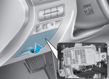
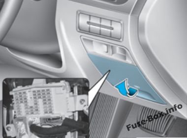
Instrument panel
The fuse box is located on the driver’s side of the instrument panel behind the cover.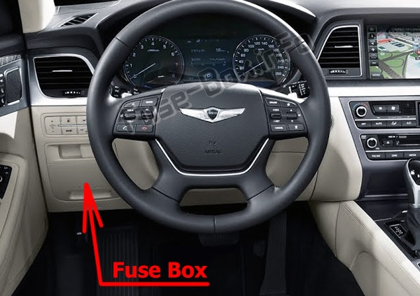
Left-hand drive vehicles
Right-hand drive vehicles
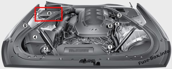
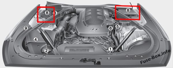
Engine compartment
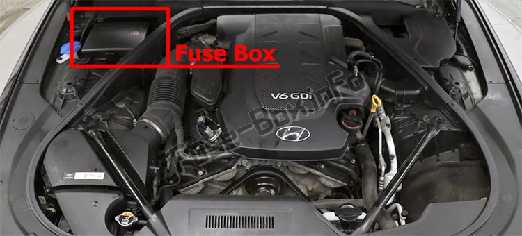
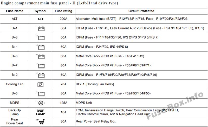
Left-hand drive vehicles
Right-hand drive vehicles
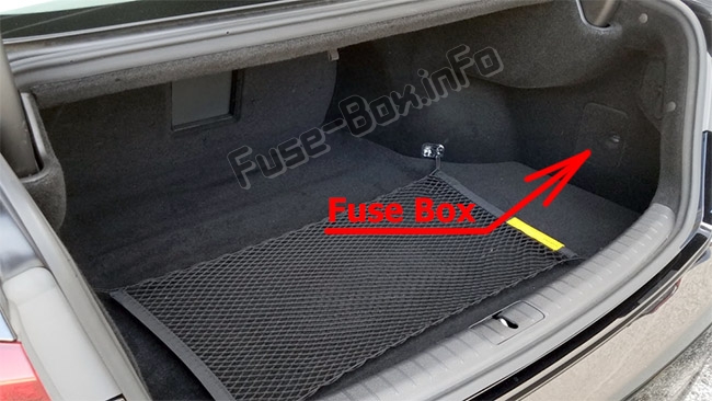
Trunk fuse panel
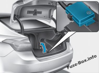
Battery box fuse panel
Fuse box diagrams
Version 1
Instrument panel
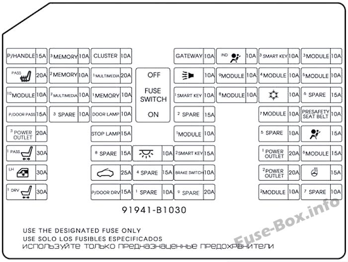
Assignment of the fuses in the instrument panel (Version 1)
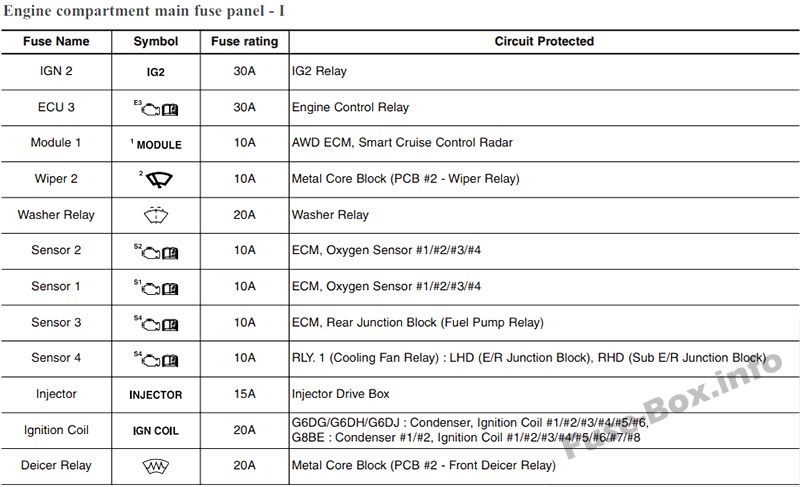
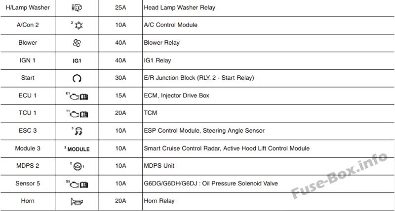
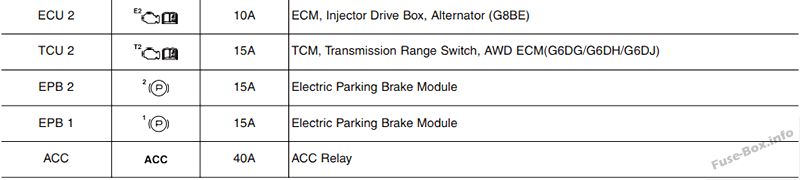
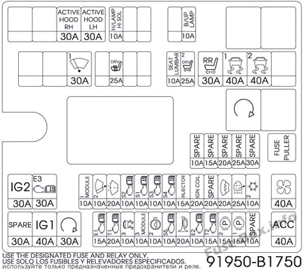
Engine compartment (Left-hand drive vehicles)
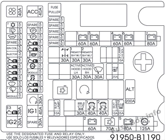
Assignment of the fuses in the Engine compartment (Version 1, Left-hand drive vehicles)
Engine compartment main fuse panel (Right-hand drive vehicles)
Assignment of the fuses in the Engine compartment main fuse panel (Right-hand drive vehicles)
Engine compartment sub fuse panel (Right-hand drive vehicles)
Assignment of the fuses in the Engine compartment sub fuse panel (Right-hand drive vehicles)

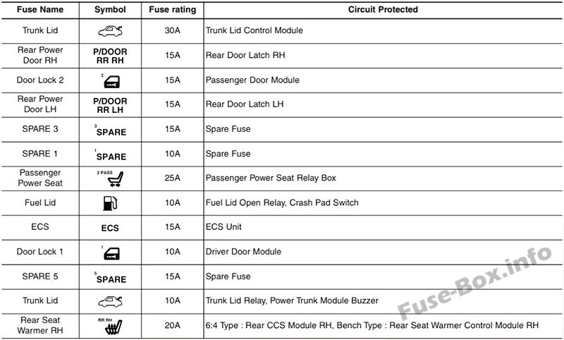
Trunk fuse panel
Assignment of the fuses in the Trunk fuse panel (Version 1)
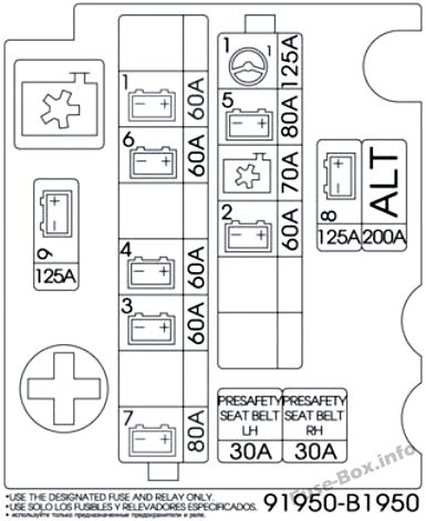
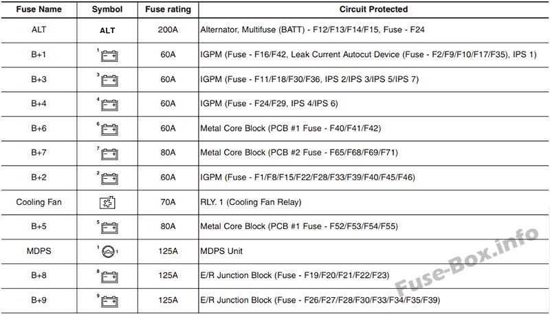
Battery box fuse panel
Assignment of the fuses in the Battery box fuse panel (Version 1)
Version 2
Instrument panel
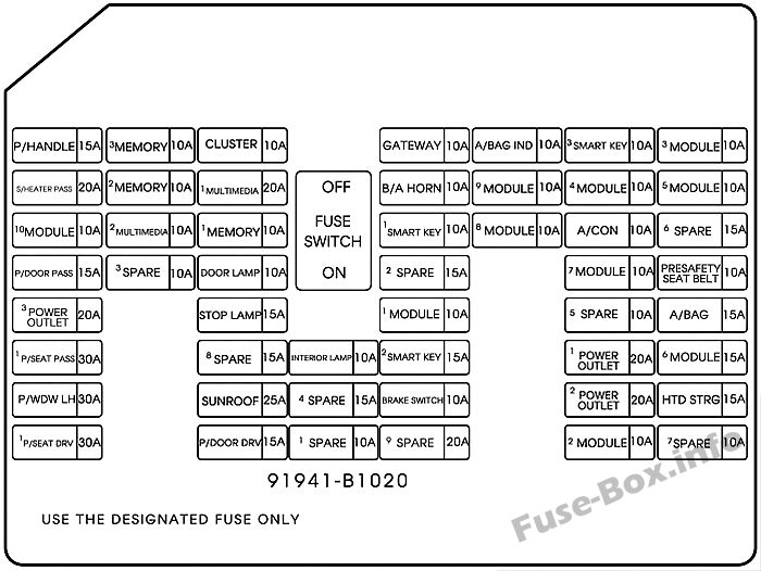
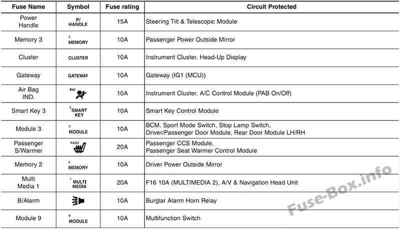
Assignment of the fuses in the instrument panel (Variant 2)
| Name | Amp rating | Circuit Protected |
|---|---|---|
| P/HANDLE | 15A | Steering Tilt & Telescopic Module |
| 3 MEMORY | 10A | Passenger Power Outside Mirror |
| CLUSTER | 10A | Instrument Cluster, Head-Up Display |
| GATEWAY | 10A | Gateway (IG1 (MCU)) |
| A/BAG IND | 10A | Instrument Cluster, A/C Control Module |
| 3 SMART KEY | 10A | Smart Key Control Module |
| 3MODULE | 10A | BCM, Sport Mode Switch, Stop Lamp Switch, Driver/Passenger Door Module, Rear Door Module LH/RH |
| S/HEATER PASS | 20A | Passenger CCS Module, Passenger Seat Warmer Control Module |
| 2 MEMORY | 10A | Driver Power Outside Mirror |
| 1 MULTI MEDIA | 20A | Fuse – MULTIMEDIA 2, A/V & Navigation Head Unit |
| B/A HORN | 10A | Burglar Alarm Horn Relay |
| 9 MODULE | 10A | Multifunction Switch |
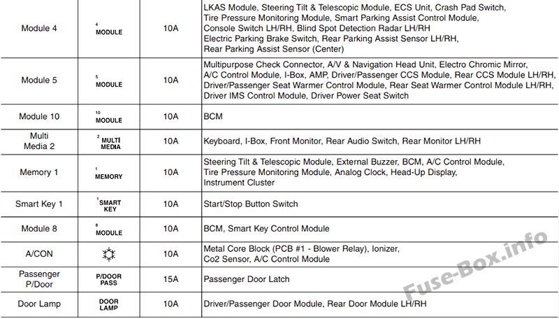
| 4 MODULE | 10A | Steering Tilt & Telescopic Module, Blind Spot Detection Radar LH/RH Crash Pad Switch, Tire Pressure Monitoring Module, Console Switch Console Switch LH/RH, Front Parking Assist Sensor LH/RH Front Parking Assist Sensor (Center) LH/RH, ECS Unit Electric Parking Brake Switch, Rear Parking Assist Sensor LH/RH Rear Parking Assist Sensor (Center) LH/RH, LKAS Module |
| 5 MODULE | 10A | Multipurpose Check Connector, A/V & Navigation Head Unit, Electro Chromic Mirror, A/C Control Module, l-Box, AMP Driver/Passenger CCS Module, Driver Power Seat Switch Driver/Passenger Seat Warmer Control Module Rear Seat Warmer Control Module LH/RH, Driver IMS Control Module |
| 10 MODULE | 10A | BCM |
| 2 MULTI MEDIA | 10A | Keyboard, l-Box, Front Monitor |
| 1 MEMORY | 10A | Steering Tilt & Telescopic Module, External Buzzer, BCM, Analog Clock A/C Control Module, Tire Pressure Monitoring Module, Security Indicator Head-Up Display, Instrument Cluster, Driver/Passenger Door Module Rear Door Module LH/RH, Power Trunk Lid Control Module |
| 1SMART KEY | 10A | Start/Stop Button Switch |
| 8 MODULE | 10A | BCM, Smart Key Control Module |
| A/CON | 10A | Metal Core Block (PCB #1 – Blower Relay), Ionizer Co2 Sensor, A/C Control Module |
| P/DOOR PASS | 15A | Passenger Door Latch |
| DOOR LAMP | 10A | Driver/Passenger Door Module, Rear Door Module LH/RH |
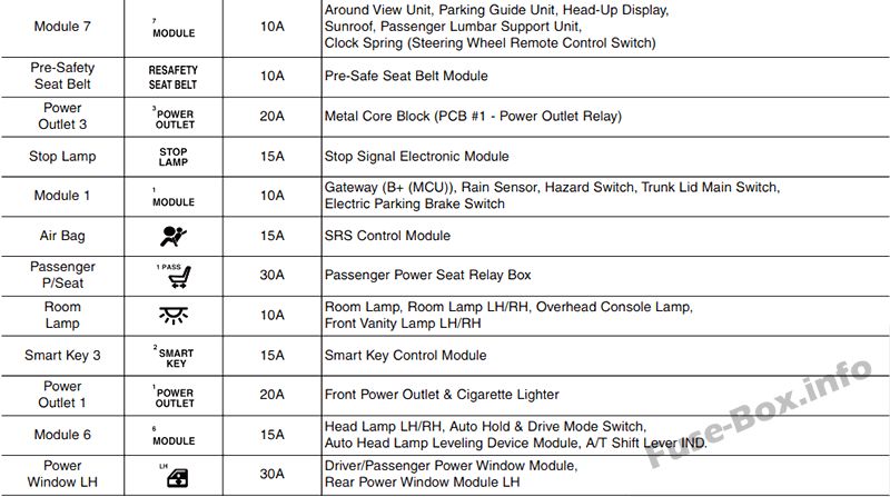
| 7 MODULE | 10A | Parking Guide Unit, Head-Up Display Sunroof, Passenger Lumbar Support Unit Clock Spring (Steering Wheel Remote Control Switch) |
| PRESAFETY SEAT BELT | 10A | Pre-Safe Seat Belt Module |
| 3 POWER OUTLET | 20A | Not Used |
| STOP LAMP | 15A | Stop Signal Electronic Module |
| 1 MODULE | 10A | Gateway (B+ (MCU)), Rain Sensor, Hazard Switch Trunk Lid Main Switch, Electric Parking Brake Switch |
| A/BAG | 15A | SRS Control Module |
| 1 P/SEAT PASS | 30A | Passenger Power Seat Relay Box |
| INTERIOR LAMP | 10A | Room Lamp, Room Lamp LH/RH, Overhead Console Lamp, Glove Box Front Vanity Lamp LH/RH, Driver/Passenger Foot Lamp, Trunk Room Lamp LH/RH |
| 2 SMART KEY | 15A | Smart Key Control Module |
| 1 POWER OUTLET | 20A | Front Power Outlet & Cigarette Lighter |
| 6 MODULE | 15A | Head Lamp LH/RH, Auto Hold & Drive Mode Switch Auto Head Lamp Leveling Device Module, A/T Shift Lever IND. |
| P/WDW LH | 30A | Driver Power Window Module, Rear Door Module LH Rear Power Window Module LH |
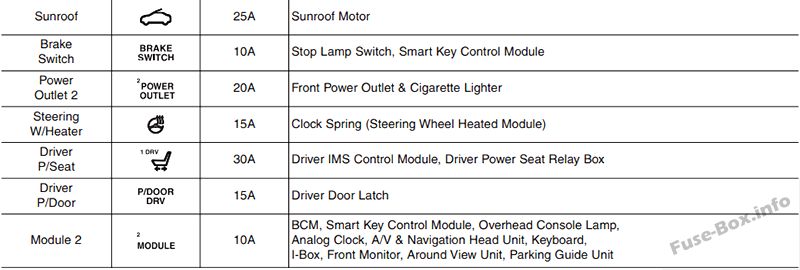
| SUNROOF | 25A | Sunroof Motor |
| BRAKE SWITCH | 10A | Stop Lamp Switch, Smart Key Control Module |
| 2 POWER OUTLET | 20A | Front Power Outlet & Cigarette Lighter |
| HTD STRG | 15A | Clock Spring (Steering Wheel Heated Module) |
| 1 P/SEAT DRV | 30A | Driver IMS Control Module, Driver Power Seat Relay Box |
| P/DOOR DRV | 15A | Driver Door Latch |
| 2 MODULE | 10A | BCM, Smart Key Control Module, Overhead Console Lamp Analog Clock, A/V & Navigation Head Unit, Keyboard l-Box, Front Monitor, Parking Guide Unit |
Engine compartment
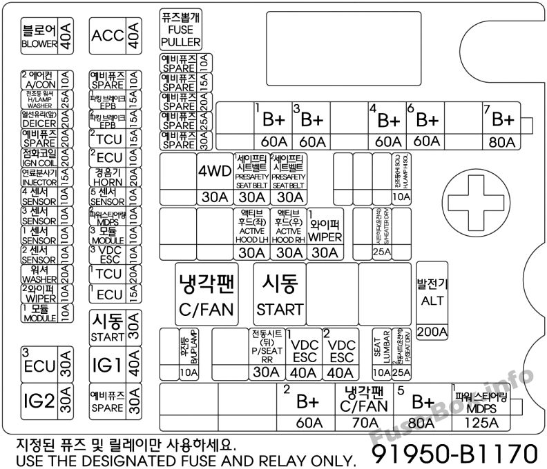
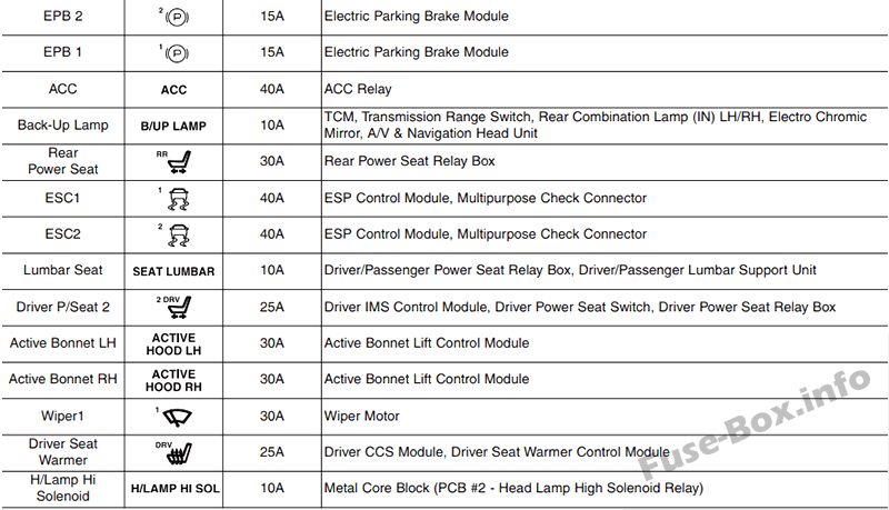
Assignment of the fuses in the Engine compartment (Variant 2)
| Name | Amp rating | Circuit Protected |
|---|---|---|
| ALT | 200A | Alternator, Multifuse (BATT) – B+2/ B+5/ MDPS 1/ C/FAN, Fuse – P/SEAT DRV 2/ P/SEAT RR/ SEAT LUMBAR/ ESC 1/ESC 2 |
| 1 B+ | 60A | IGPM (Fuse – BRAKE SWITCH, Leak Current Autocut Device (Fuse – INTERIOR LAMP/ MULTI MEDIA 1/ MEMORY 1/ MEMORY 21 MEMORY 3), IPS 1) |
| 3 B+ | 60A | IGPM (Fuse – SMART KEY 1/ SMART KEY 2/ MODULE 1/ B/A HORN, IPS 2/IPS 3/IPS 5/IPS 7) |
| 4 B+ | 60A | IGPM (Fuse – DOOR LAMP/ STOP LAMP, IPS 4/IPS 6) |
| 6 B+ | 60A | Metal Core Block (PCB #1 Fuse – ECU 3/ IG2/ MODULE 1) |
| 7 B+ | 80A | Metal Core Block (PCB #2 Fuse – HORN/ ACC/ EPB 1/ EPB 2) |
| 2 B+ | 60A | IGPM (Fuse – P/HANDLE/ P/WDW LH/ P/SEAT PASS 1/ S/HEATER PASS/ MODULE 10/ SUNROOF/ P/DOOR DRV/ P/DOOR PASS) |
| C/FAN | 70A | RLY. 1 (C/Fan Relay) |
| 5 B+ | 80A | Metal Core Block (PCB #1 Fuse – BLOWER/ DEICER/ H/LAMP WASHER) |
| MDPS 1 | 125A | MDPS Unit |
| B/UP LAMP | 10A | TCM, Transmission Range Switch, Rear Combination Lamp (IN) LH/RH, Electro Chromic Mirror, A/V & Navigation Head Unit |
| P/SEAT RR | 30A | Not Used |
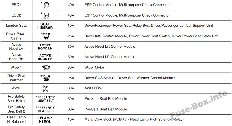
| 1 ESC | 40A | ESC Module, Multipurpose Check Connector |
| 2 ESC | 40A | ESC Module, Multipurpose Check Connector |
| SEAT LUMBAR | 10A | Driver/Passenger Power Seat Relay Box, Driver/Passenger Lumbar Support Unit |
| 2 P/SEAT DRV | 25A | Driver IMS Control Module, Driver Power Seat Switch, Driver Power Seat Relay Box |
| ACTIVE HOOD LH | 30A | Not Used |
| ACTIVE HOOD RH | 30A | Not Used |
| WIPER | 30A | Wiper Motor |
| S/HEATER DRV | 25A | Driver CCS Module, Driver Seat Warmer Control Module |
| 4WD | 30A | 4WD ECM |
| 1 PRESAFETY SEAT BELT | 30A | Pre-Safe Seat Belt Module |
| 2 PRESAFETY SEAT BELT | 30A | Pre-Safe Seat Belt Module |
| H/LAMP HI SOL | 10A | Metal Core Block (PCB #2 – Head Lamp High Solenoid Relay) |
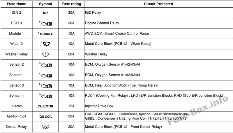
| IG2 | 30A | IG2 Relay |
| 3 ECU | 30A | Engine Control Relay |
| 1 MODULE | 10A | 4WD ECM, Smart Cruise Control Radar, Active Air Flap |
| 2 WIPER | 10A | Metal Core Block (PCB #2 – Wiper Relay) |
| WASHER | 20A | Washer Relay |
| 2 SENSOR | 10A | ECM, Oxygen Sensor #1/#2/#3/#4 |
| 1 SENSOR | 10A | ECM, Oil Control Valve #1/#2/#3/#4, Canister Close Valve, Purge Control Solenoid Valve, Variable Intake Solenoid Valve #1/#2 |
| 3 SENSOR | 10A | ECM, Rear Junction Block (Fuel Pump Relay) |
| 4 SENSOR | 10A | C/Fan Relay, Camshaft Position Valve (G8BE) |
| INJECTOR | 15A | Injector Drive Box |
| IGN COIL | 20A | G6DJ : Condenser, Ignition Coil #1/#2/#3/#4/#5/#6, G8BE : Condenser #1/#2, Ignition Coil #1 /#2/#3/#4/#5/#6/#7/#8 |
| DEICER | 20A | Metal Core Block (PCB #2 – Front Deicer Relay) |
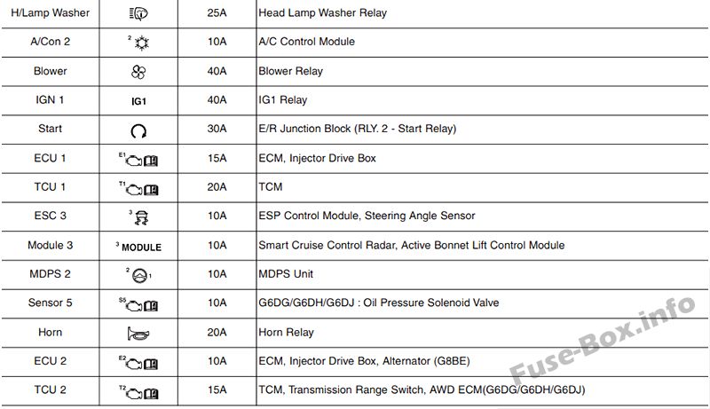
| H/LAMP WASHER | 25A | Head Lamp Washer Relay |
| 2 A/CON | 10A | A/C Control Module |
| BLOWER | 40A | Blower Relay |
| IG1 | 40A | IG1 Relay |
| START | 30A | E/R Junction Block (RLY. 2 – Start Relay) |
| 1 ECU | 15A | ECM, Injector Drive Box |
| 1 TCU | 20A | TCM |
| 3 ESC | 10A | ESC Module, Steering Angle Sensor |
| 3 MODULE | 10A | Smart Cruise Control Radar, Active Air Flap |
| 2 MDPS | 10A | MDPS Unit |
| 5 SENSOR | 10A | G6DJ : Oil Pressure Solenoid Velve |
| HORN | 20A | Horn Relay |
| 2 ECU | 10A | ECM, Injector Drive Box, Alternator (G8BE) |
| 2 TCU | 15A | TCM, Transmission Range Switch, 4WD ECM |
| 2 EPB | 15A | Electric Parking Brake Module |
| 1 EPB | 15A | Electric Parking Brake Module |
| ACC | 40A | ACC Relay |
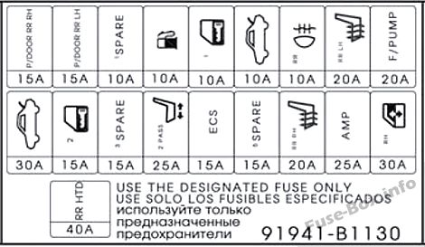
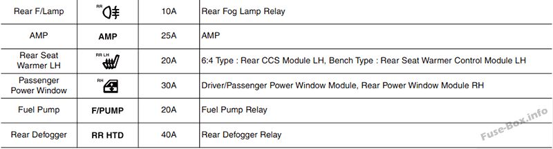
Trunk fuse panel
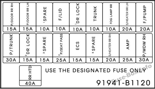
Assignment of the fuses in the Trunk fuse panel (Variant 2)
| Name | Amp rating | Circuit Protected |
|---|---|---|
| P/TRUNK | 30A | Power Trunk Lid Control Module |
| P/DOOR RR RH | 15A | Rear Door Latch RH |
| 2 DR LOCK | 15A | Passenger Door Module |
| P/DOOR RR LH | 15A | Rear Door Latch LH |
| 3 SPARE | 15A | Spare Fuse |
| 1 SPARE | 10A | Spare Fuse |
| 2 P/SEAT PASS | 25A | Passenger Power Seat Relay Box |
| F/LID | 10A | Fuel Lid Open Relay, Crash Pad Switch |
| ECS | 15A | ECS Unit |
| 1 DR LOCK | 10A | Driver Door Module |
| 5 SPARE | 15A | Spare Fuse |
| TRUNK | 10A | Trunk Lid Relay, Power Trunk Module Buzzer |
| S/HEATER RR RH | 20A | Rear Seat Warmer Control Module RH |
| FOG LAMP RR | 10A | Not Used |
| AMP | 25A | AMP |
| S/HEATER RR LH | 20A | Rear Seat Warmer Control Module LH |
| P/WDW RH | 30A | Passenger Power Window Module, Rear Power Window Module RH |
| F/PUMP | 20A | Fuel Pump Relay |
| RR HTD | 40A | Rear Defogger Relay |
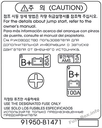
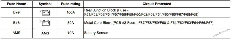
Battery box fuse panel
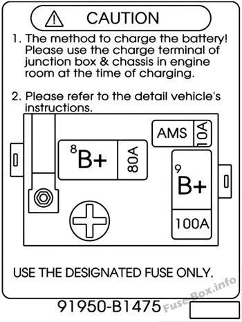
Assignment of the fuses in the Battery box fuse panel (Variant 2)
| Name | Amp rating | Circuit Protected |
|---|---|---|
| 9 B+ | 100A | Rear Junction Block (Fuse – RR HTD/ P/TRUNK/ ECS/ F/LID/ P/DOOR RR RH/ DR LOCK 2/ P/DOOR RR LH/ AMP/ P/SEAT PASS 2/ DR LOCK 1/TRUNK/ S/HEATER RR RH/ S/HEATER RR LH/ P/WDW RH/ F/PUMP) |
| 8 B+ | 80A | Metal Core Block (PCB #2 Fuse – TCU/ ECU 1/ START/ IG 1) |
| AMS | 10A | Battery Sensor |


