

See other Hyundai Azera:

Fuse Layout Hyundai Azera 2011-2017
Contents

Cigar lighter (power outlet) fuse in the Hyundai Azera is the fuse #9 in the Instrument panel fuse box.
Table of Contents
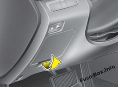
Fuse box location
Fuse box location
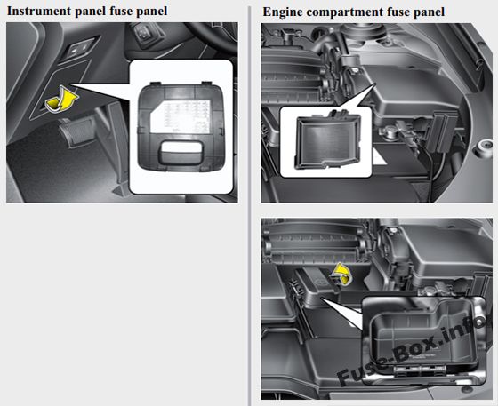
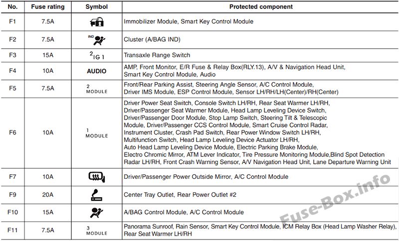
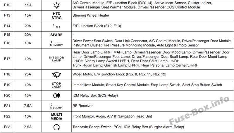
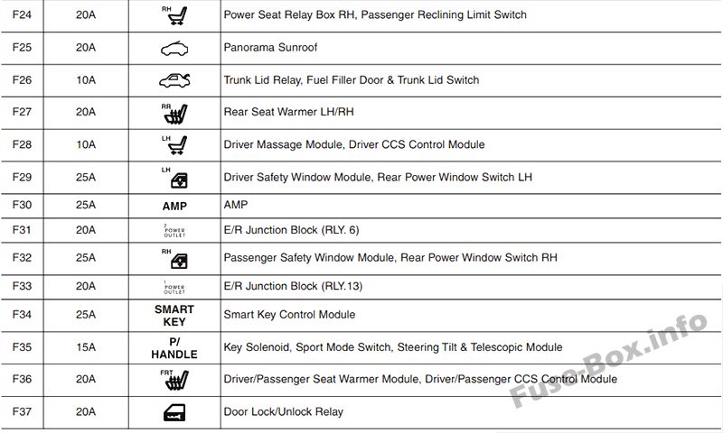
Instrument panel
The fuse box is located in the instrument panel (on the driver’s side), behind the cover.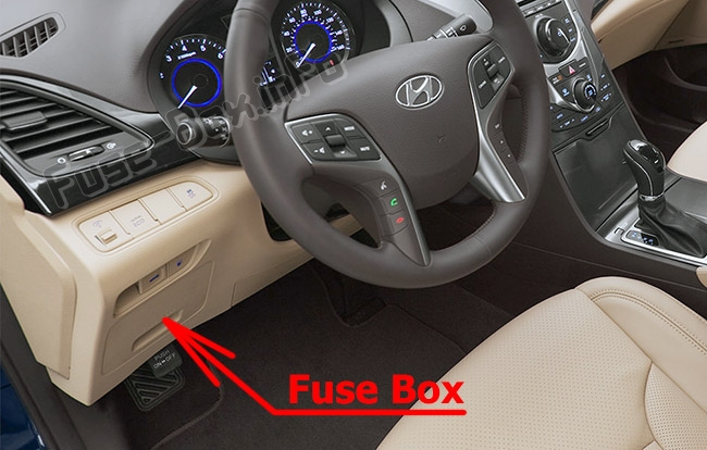
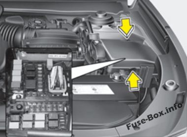
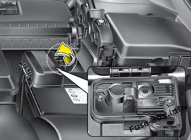
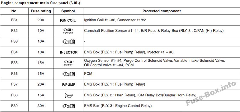
Engine compartment
The fuse box is located in the engine compartment (left-side).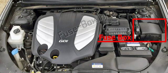
Main fuse
2011, 2012, 2013, 2014
2011, 2012, 2013, 2014
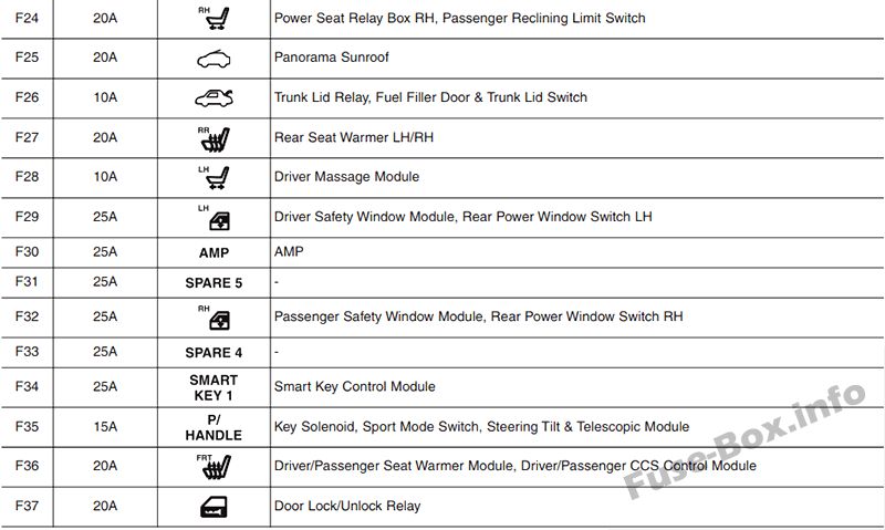
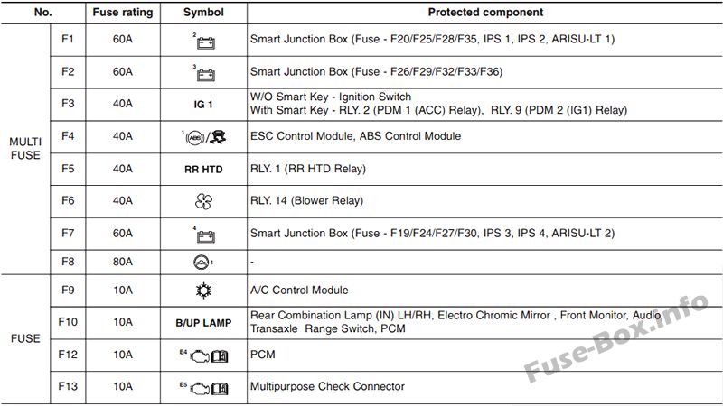
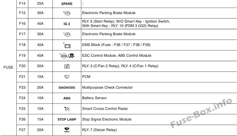
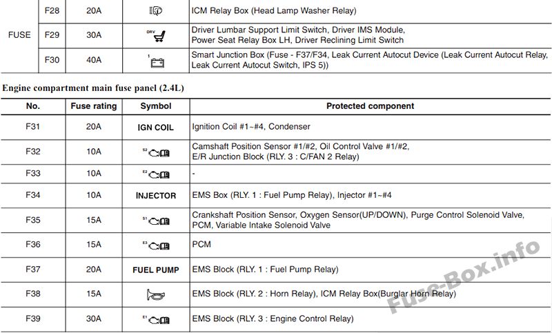
Assignment of the fuses in the instrument panel (2011-2014)
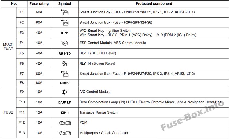
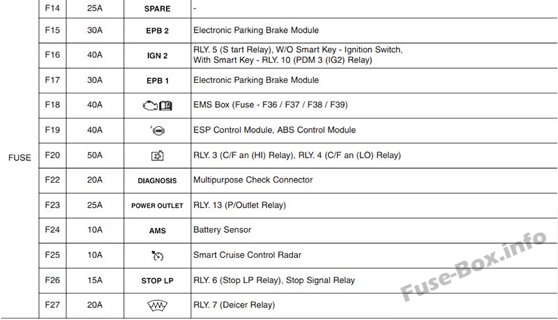
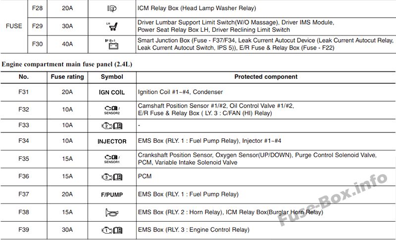
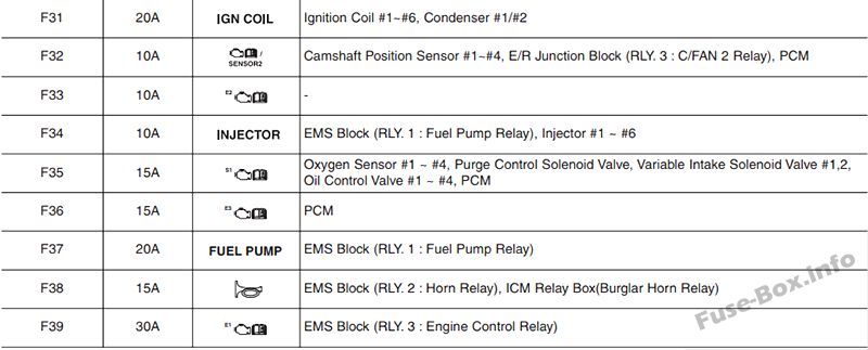
Assignment of the fuses in the engine compartment (2011-2014)
2015
2015
Assignment of the fuses in the instrument panel (2015)
Assignment of the fuses in the engine compartment (2015)
Fuse box diagrams 2016, 2017
Fuse box diagrams 2016, 2017
Instrument panel
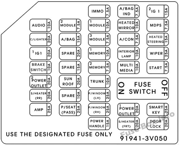
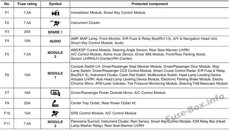
Assignment of the fuses in the instrument panel (2016, 2017)
| No. | Amp rating | Symbol | Protected component |
|---|---|---|---|
| 1 | 7.5A | IMMO | Smart Key Control Module |
| 2 | 7.5A | A/BAG IND | Instrument Cluster |
| 3 | 20A | SPARE | – |
| 4 | 10A | AUDIO | AMR Smart Key Control Module, Telematics Unit,E/R Junction Block (Power Outlet Relay), A/V & Navigation Head Unit,Front Monitor (Audio/Navigation), Audio, A/C Control Module |
| 5 | 7.5A | MODULE 2 | ESC Control Module, Rear Seat Warmer LH/RH, Console Switch, A/C Control Module, Rear Power Window Switch LH/RH, Driver IMS Module, Rear Parking Assist Sensor LH/RH/LH(Center)/RH(Center) |
| 6 | 10A | MODULE 1 | Driver Power Seat Switch, Driver/Passenger Seat Warmer Module, Driver/Passenger Door Module, Stop Lamp Switch, Crash Pad Switch, Driver/Passenger CCS Control Module, Steering Tilt & Telescope Module, Instrument Cluster, Blind Spot Detection Radar LH/RH, Multifunction Switch, Forward Collision Warning Unit, Lane Departure Warning Unit, Electro Chromic Mirror, ATM Lever Indicator, Tire Pressure Monitoring Module, Telematics Unit |
| 7 | 10A | HTD MIRR | Driver/Passenger Power Outside Mirror, A/C Control Module |
| 8 | 7.5A | MDPS | MDPS Unit |
| 9 | 20A | C/LIGHTER | Center Tray Outlet |
| 10 | 15A | A/BAG | SRS Control Module, Passenger Occupant Detection Sensor, A/C Control Module |
| 11 | 7.5A | MODULE 3 | Smart Key Control Module, Rear Seat Warmer LH/RH |
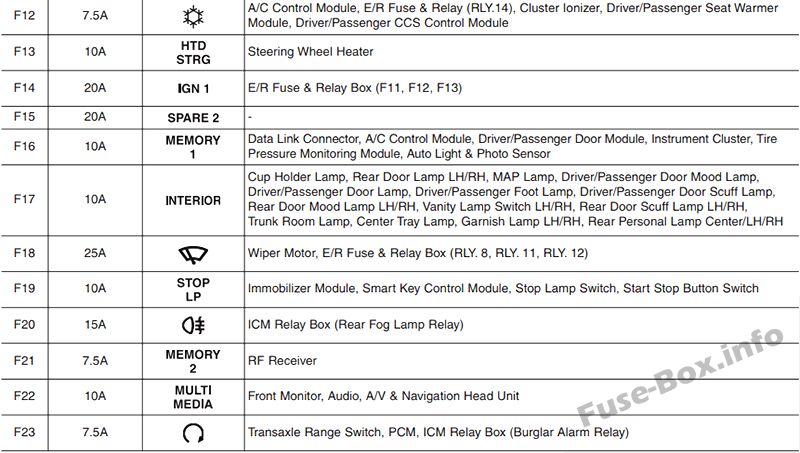
| 12 | 7.5A | A/CON | A/C Control Module, E/R Junction Block (Blower Relay), Driver/Passenger Seat Warmer Module, Active Incar Sensor, Driver/Passenger CCS Control Module |
| 13 | 15A | IG1 2 | Steering Wheel Heater |
| 14 | 20A | IG1 1 | E/R Junction Block (ECU 5 10A, ECU 4 10A) |
| 15 | 10A | MEMORY 1 | Driver Power Seat Switch, Data Link Connector, A/C Control Module, Driver/Passenger Door Module, Instrument Cluster, Tire Pressure Monitoring Module, Auto Light & Photo Sensor |
| 16 | 10A | INTERIOR LAMP | Rear Door Lamp LH/RH, MAP Lamp, Garnish Lamp LH/RH, Driver/Passenger Door Mood Lamp, Driver/Passenger Door Lamp, Driver/Passenger Foot Lamp, Driver/Passenger Door Scuff Lamp, Rear Door Mood Lamp LH/RH, Vanity Lamp Switch LH/RH, Rear Door Scuff Lamp LH/RH, Trunk Room Lamp, Rear Personal Lamp Center/LH/RH |
| 17 | 25A | WIPER | Wiper Motor, E/R Junction Block (Washer Relay, Wiper (LO) Relay, Wiper (HI) Relay) |
| 18 | 10A | STOP LAMP | Smart Key Control Module, Stop Lamp Switch, Start Stop Button Switch |
| 19 | 7.5A | MEMORY 2 | RF Receiver |
| 20 | 10A | MULTI MEDIA | Front Monitor (Audio/Navigation), A/V & Navigation Head Unit, Telematics Unit, Audio |
| 21 | 7.5A | START | Transaxle Range Switch, PCM |
| 22 | 20A | SUNROOF | Panorama Sunroof |
| 23 | 10A | TRUNK | Trunk Lid Relay, Fuel Filler Door & Trunk Lid Switch |
| 24 | 20A | S/HEATER RR | Rear Seat Warmer LH/RH |
| 25 | 10A | DRV P/SEAT | – |
| 26 | 25A | P/ WDW LH | Driver Safety Window Module, Rear Power Window Switch LH |
| 27 | 25A | AMP | AMP |
| 28 | 25A | PASS P/SEAT | Passenger Reclining Limit Switch, Power Seat Relay Box RH |
| 29 | 25A | P/WDW RH | Passenger Safety Window Module, Rear Power Window Switch RH |
| 30 | 25A | SMART KEY | Smart Key Control Module |
| 31 | 15A | P/HANDLE | Sport Mode Switch, Steering Tilt & Telescopic Module |
| 32 | 20A | S/HEATER FRT | Driver/Passenger Seat Warmer Module, Driver/Passenger CCS Control Module |
| 33 | 20A | DR LOCK | Door Lock/Unlock Relay, ICM Relay Box (Two Turn Unlock Relay) |
Engine compartment
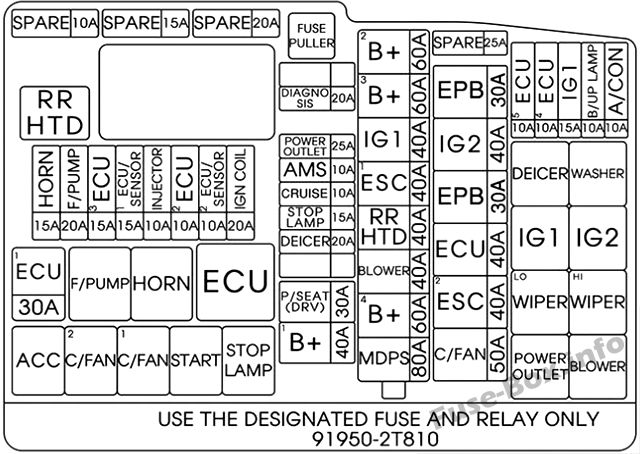
Assignment of the fuses in the Engine compartment (2016, 2017)
| No. | Amp rating | Symbol | Protected component |
|---|---|---|---|
| MULTI FUSE: | |||
| 1 | 60A | B+2 | Smart Junction Box (P/HANDLE 15A, SUNROOF 20A, DRV P/SEAT 10A, PASS P/SEAT 25A, IPS 2, ARISU-LT 1) |
| 2 | 60A | B+3 | Smart Junction Box (P/WDW 25A, P/WDW RH 25A, S/HEATER FRT 10A ( TRUNK 10A, P/OUTLET 1 20 A) |
| 3 | 40A | IG1 | PDM 1 (ACC) Relay PDM 2 (IG1) Relay |
| 4 | 40A | ESC1 | ESC Module |
| 5 | 40A | RR HTD | RR HTD Relay |
| 6 | 40A | BLOWER | Blower Relay |
| 7 | 60A | B+4 | Smart Junction Block (STOP LAMP 10A, S/HEATER RR 20A, IPS 3/4, ARISU-LT 2, AMP 25A, P/OUTLET 2 20A) |
| 8 | 80A | MDPS | MDPS Unit |
| FUSE: | |||
| 9 | 10A | A/CON | A/C Control Module |
| 10 | 10A | B/UP LAMP | Rear Combination Lamp (IN) LH/RH, Electro Chromic Mirror, Audio, Front Monitor |
| 11 | 10A | ECU 4 | PCM, IDB(lnjector Driver Box) |
| 12 | 10A | ECU 5 | Multipurpose Check Connector |
| 13 | 30A | EPB 2 | Electronic Parking Brake Module |
| 14 | 40A | IG 2 | Start Relay, PDM 3 (IG2) Relay |
| 15 | 30A | EPB 1 | Electronic Parking Brake Module |
| 16 | 40A | B+5 | EMS Block (ECU 3 15A, ECU 1 30A, F/PUMP 20A, HORN 15A) |
| 17 | 40A | ESC 2 | ESC Module |
| 18 | 50A | C/FAN | C/Fan Relay |
| 19 | 20A | DIAGNOSIS | Multipurpose Check Connector |
| 20 | 10A | AMS | Battery Sensor |
| 21 | 10A | CRUISE | Smart Cruise Control Radar |
| 22 | 15A | STOP LAMP | Stop Signal Electronic Module |
| 23 | 20A | DEICER | Deicer Relay |
| 24 | 30A | DRV P/SEAT | Driver Lumbar Support Limit Switch, Driver IMS Module, Power Seat Relay Box LH, Driver Reclining Limit Switch |
| 25 | 40A | B+1 | Smart Junction Box (DR LOCK 20A, SMART KEY 1 25A, Leak Current Autocut Device (Leak Current Autocut Relay, Leak Current Autocut Switch, IPS 5)) |
| 26 | 20A | IGN COIL | Ignition Coil #1 -#6, Condenser #1/#2 |
| 27 | 10A | SENSOR 2 | IDB (Injector Driver Box), PCM, Purge Control Solenoid Valve, Oil Control Valve #1 – #4, Variable Intake Solenoid Valve #1, #2, Canister Close Valve, E/R Junction (C/FAN Relay) |
| 28 | 10A | ECU 2 | IDB (Injector Driver Box) |
| 29 | 10A | INJECTOR | PCM, EMS Box (F/Pump Relay) |
| 30 | 15A | SENSOR 1 | PCM, Oxygen Sensor #1 ~#4 |
| 31 | 15A | ECU 3 | PCM, IDB (Injector Driver Box) |
| 32 | 20A | F/PUMP | EMS Block (F/Pump Relay) |
| 33 | 15A | HORN | EMS Block (Horn Relay), ICM Relay Box(Burglar Horn Relay) |
| 34 | 30A | ECU 1 | EMS Block (Engine Control Relay) |


