


Fuse Layout Ford F250 / F350 / F450 / F550 2013-2015
Contents

Cigar lighter (power outlet) fuses in the Ford F-250 / F-350 / F-450 / F-550 are the fuses №82, 83, 87, 88, 92 and 93 in the Engine compartment fuse box.
Table of Contents
Fuse box location
Passenger compartment
The fuse panel is located in the passenger’s footwell behind the cover.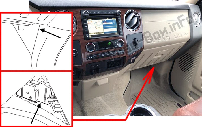
Engine compartment
The power distribution box is located in the engine compartment.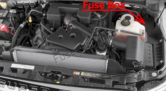
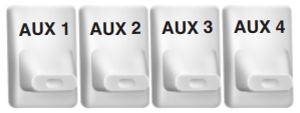
UPFITTER CONTROLS (IF EQUIPPED)
The upfitter option package provides four switches, mounted in the center of the instrument panel. These switches will only operate while the ignition is in the on position, whether the engine is running or not. However, it is recommended that the engine remain running to maintain battery charge when using the upfitter switches for extended duration or higher current draws. (This is even more important for vehicles with diesel engines since the glow plugs are also draining battery power when the ignition key is in the on position.)
When switched on, they provide 8 amps, 12 amps or 20 amps of electrical battery power for a variety of personal or commercial uses.
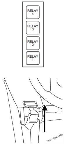
Relay box
There will also be a relay box located on the driver’s side end of the instrument panel. See your authorized dealer for service.
There will also be one power lead for each switch found as a blunt-cut and sealed wire located below the instrument panel and to the left of the steering column.
Fuse box diagrams
2013
Passenger compartment
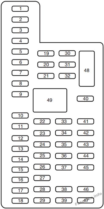
Assignment of the fuses in the Passenger compartment (2013)
| № | Amp rating | Protected circuits |
|---|---|---|
| 1 | 30A | Not used (spare) |
| 2 | 15A | Upfitter relay #4 |
| 3 | 30A | Smart window motor |
| 4 | 10A | Interior lights, Hood lamp |
| 5 | 20A | Moonroof |
| 6 | 5A | Driver seat module |
| 7 | 7.5A | Driver seat switch, Driver lumbar motor |
| 8 | 10A | Power mirror switch |
| 9 | 10A | Upfitter relay #3 |
| 10 | 10A | Run/accessory relay, Customer access feed |
| 11 | 10A | Instrument cluster |
| 12 | 15A | Interior lighting, Lighted running board lamps |
| 13 | 15A | Right turn signals and brake lamps, Right trailer tow stop turn relay |
| 14 | 15A | Left turn signals and brake lamps, Left trailer tow stop turn relay |
| 15 | 15A | High-mounted stop lamps, Backup lamps, Trailer tow backup relay, Reverse signal interior mirror |
| 16 | 10A | Right low beam headlamp |
| 17 | 10A | Left low beam headlamp |
| 18 | 10A | Keypad illumination, Passive anti-theft indicator, Powertrain control module, Brake shift interlock |
| 19 | 20A | Subwoofer, Amplifier |
| 20 | 20A | Power door locks |
| 21 | 10A | Brake on/off switch |
| 22 | 20A | Horn |
| 23 | 15A | Not used (spare) |
| 24 | 15A | Steering wheel control module, Diagnostic connector, Power fold mirror relay, Remote keyless entry, Electronic finish panel |
| 25 | 15A | Not used (spare) |
| 26 | 5A | Steering wheel control module |
| 27 | 20A | Not used (spare) |
| 28 | 15A | Ignition switch |
| 29 | 20A | SYNC, GPS module, Radio faceplate |
| 30 | 15A | Parking lamp relay, Trailer tow parking lamp relay |
| 31 | 5A | Trailer brake controller (brake signal), Customer access |
| 32 | 15A | Moonroof motor, Telescoping mirror switch, Auto dimming mirrors, Power inverter, Driver and passenger door lock switch illumination, Rear heated seat switch illumination |
| 33 | 10A | Restraint control module |
| 34 | 10A | Heated steering wiieel module, Rear heated seats module |
| 35 | 5A | Select shift switch, Reverse park aid module, Trailer brake control module |
| 36 | 10A | Fuel tank select switch |
| 37 | 10A | PTC heater |
| 38 | 10A | AM/FM radio faceplate |
| 39 | 15A | High beam headlamps |
| 40 | 10A | Parking lamps (in mirrors), Roof marker lamps |
| 41 | 7.5A | Passenger airbag deactivation indicator |
| 42 | 5A | Not used (spare) |
| 43 | 10A | Wiper relay |
| 44 | 10A | Upfitter swatches |
| 45 | 5A | Not used (spare) |
| 46 | 10A | Climate control |
| 47 | 15A | Fog lamps, Fog lamp indicator (in switch) |
| 48 | 30A Circuit Breaker | Power windows switch, Power rear sliding window swatch |
| 49 | Relay | Delayed accessory |
Engine compartment
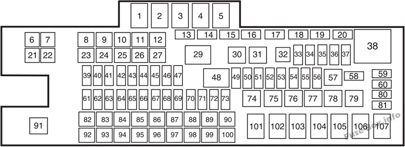
Assignment of the fuses in the Power distribution box (2013)
| № | Amp rating | Protected circuits |
|---|---|---|
| 1 | Relay | Blower motor |
| 2 | — | Not used |
| 3 | Relay | Urea heaters (diesel engine) |
| 4 | — | Not used |
| 5 | Relay | Rear window defroster, Heated mirrors |
| 6 | — | Not used |
| 7 | 50A* | Rear window defroster, Heated mirrors |
| 8 | 30A* | Passenger seat |
| 9 | 30A* | Driver seat |
| 10 | — | Not used |
| 11 | — | Not used |
| 12 | 30A* | Smart window motor |
| 13 | — | Not used |
| 14 | — | Not used |
| 15 | Diode | Fuel pump (diesel engine) |
| 16 | — | Not used |
| 17 | 15A** | Heated mirror |
| 18 | — | Not used |
| 19 | — | Not used |
| 20 | — | Not used |
| 21 | — | Not used |
| 22 | 30A* | Trailer tow electric brake |
| 23 | 40A* | Blower motor |
| 24 | — | Not used |
| 25 | 30A* | Wipers |
| 26 | 30A* | Trailer tow park lamps |
| 27 | 25A* | Urea heaters (diesel engine) |
| 28 | — | Buss bar |
| 29 | Relay | Trailer tow park lamps |
| 30 | Relay | A/C clutch |
| 31 | Relay | Wipers |
| 32 | — | Not used |
| 33 | 15 A** | Vehicle power 1 |
| 34 | 15 A** | Vehicle power 2 (diesel engine) |
| 34 | 20A** | Vehicle power 2 (gas engine) |
| 35 | 10A** | Vehicle power 3 |
| 36 | 15A** | Vehicle power 4 (diesel engine) |
| 36 | 20A** | Vehicle power 4 (gas engine) |
| 37 | 10 A** | Vehicle power 5 (diesel engine) |
| 38 | Relay | Powertrain control module (diesel engine), Electronic control module (gas engine) |
| 39 | 10 A** | 4×4 hub lock |
| 40 | 15A** | 4×4 electronic lock |
| 41 | — | Not used |
| 42 | 20A** | Rear heated seats |
| 43 | — | Not used |
| 44 | — | Not used |
| 45 | 10 A** | Run/start relay coil |
| 46 | 10 A** | Transmission control module keep-alive power (diesel engine) |
| 47 | 10 A** | A/C clutch feed |
| 48 | Relay | Run/start |
| 49 | 10 A** | Rearview camera system |
| 50 | 10 A** | Blower motor relay coil |
| 51 | — | Not used |
| 52 | 10 A** | Powertrain control module / Electronic control module / Transmission control module run/start |
| 53 | 10 A** | 4×4 module |
| 54 | 10 A** | Anti-lock brake system run/start |
| 55 | 10 A** | Rear window defroster coil, Battery charge coil |
| 56 | 20A** | Passenger compartment fuse panel run/start feed |
| 57 | Relay | Fuel pump |
| 58 | — | Not used |
| 59 | — | Not used |
| 60 | — | Not used |
| 61 | — | Not used |
| 62 | — | Not used |
| 63 | — | Not used |
| 64 | — | Not used |
| 65 | — | Not used |
| 66 | 20A** | Fuel pump |
| 67 | — | Not used |
| 68 | 10A** | Fuel pump relay coil |
| 69 | — | Not used |
| 70 | 10A** | Trailer tow backup lamp |
| 71 | 10A** | Canister vent (gas engine) |
| 72 | 10A** | Powertrain control module / Electronic control module relay coil feed keep-alive power |
| 73 | — | Not used |
| 74 | Relay | Trailer tow left-hand stop/turn |
| 75 | Relay | Trailer tow right-hand stop/turn |
| 76 | Relay | Backup lamp |
| 77 | — | Not used |
| 78 | — | Not used |
| 79 | — | Not used |
| 80 | — | Not used |
| 81 | — | Not used |
| 82 | 20 A* | Auxiliary power point #2 |
| 83 | 20 A* | Auxiliary power point #1 |
| 84 | 30A* | 4×4 shift motor |
| 85 | 30A* | Heated/cooled seats |
| 86 | 25A* | Anti-lock brake system coil feed |
| 87 | 20 A* | Auxiliary power point #5 |
| 88 | 20 A* | Auxiliary power point #6 |
| 89 | 40 A* | Starter motor |
| 90 | 25 A* | Trailer tow battery charge |
| 91 | — | Not used |
| 92 | 20 A* | Auxiliary power point #4 |
| 93 | 20 A* | Auxiliary power point #3 |
| 94 | 25 A* | Upfitter #1 |
| 95 | 25 A* | Upfitter #2 |
| 96 | 50A* | Anti-lock brake system pump |
| 97 | 40 A* | Inverter |
| 98 | — | Not used |
| 99 | 40 A* | Instrument panel power inverter |
| 100 | 25 A* | Trailer tow turn signals |
| 101 | Relay | Starter |
| 102 | Relay | Trailer tow battery charge |
| 103 | — | Not used |
| 104 | — | Not used |
| 105 | — | Not used |
| 106 | — | Not used |
| 107 | — | Not used |
| * Cartridge fuses ** Mini fuses |
UPFITTER CONTROLS (IF EQUIPPED)
| Switch | Circuit Number | Wire Color | Amp Rating |
|---|---|---|---|
| AUX 1 | CAC05 | Yellow | 25A |
| AUX 2 | CAC06 | Green with Brown Trace | 25A |
| AUX 3 | CAC07 | Violet with Green Trace | 10A |
| AUX 4 | CAC08 | Brown | 15A |
2014
Passenger compartment
Assignment of the fuses in the Passenger compartment (2014)
| № | Amp rating | Protected components |
|---|---|---|
| 1 | 30A | Not used (spare) |
| 2 | 15A | Auxiliary switch relay #4 |
| 3 | 30A | Passenger smart window motor |
| 4 | 10A | Interior lights, Hood lamp |
| 5 | 20A | Moonroof |
| 6 | 5A | Driver seat module |
| 7 | 7.5 A | Driver seat switch, Driver lumbar motor |
| 8 | 10A | Power mirror switch |
| 9 | 10A | Auxiliary switch relay #3 |
| 10 | 10A | Run/accessory relay, Customer access feed |
| 11 | 10A | Instrument cluster |
| 12 | 15A | Interior lighting, Lighted running board lamps |
| 13 | 15A | Right turn signals and brake lamps, Right trailer tow stop turn relay |
| 14 | 15A | Left turn signals and brake lamps, Left trailer tow stop turn relay |
| 15 | 15A | High-mounted stop lamps, Backup lamps, Trailer tow backup relay, Reverse signal interior mirror |
| 16 | 10A | Right low beam headlamp |
| 17 | 10A | Left low beam headlamp |
| 18 | 10A | Keypad illumination, Passive anti-theft transceiver, Powertrain control module, Brake shift interlock |
| 19 | 20A | Subwoofer, Amplifier |
| 20 | 20A | Power door locks |
| 21 | 10A | Brake on/off switch |
| 22 | 20A | Horn |
| 23 | 15A | Not used (spare) |
| 24 | 15A | Steering wheel control module, Diagnostic connector, Power fold mirror relay, Remote keyless entry, Electronic finish panel |
| 25 | 15A | Not used (spare) |
| 26 | 5A | Steering wheel control module |
| 27 | 20A | Not used (spare) |
| 28 | 15A | Ignition switch |
| 29 | 20A | SYNC, GPS module, Radio faceplate |
| 30 | 15A | Parking lamp relay, Trailer tow parking lamp relay |
| 31 | 5A | Trailer brake controller (brake signal), Customer access |
| 32 | 15A | Moonroof motor, Telescoping mirror switch, Auto dimming mirrors, Power inverter, Driver and passenger door lock switch illumination, Rear heated seat switch illumination, Driver and passenger smart window motor, Passenger window switch |
| 33 | 10A | Restraint control module |
| 34 | 10A | Heated steering wheel module, Rear heated seats module |
| 35 | 5A | Select shift switch, Reverse park aid module, Trailer brake control module |
| 36 | 10A | Fuel tank select switch |
| 37 | 10A | Positive temperature coefficient heater |
| 38 | 10A | AM/FM radio faceplate |
| 39 | 15A | High beam headlamps |
| 40 | 10A | Parking lamps (in mirrors), Roof marker lamps |
| 41 | 7.5 A | Passenger airbag deactivation indicator |
| 42 | 5A | Not used (spare) |
| 43 | 10A | Wiper relay |
| 44 | 10A | Auxiliary switches |
| 45 | 5A | Not used (spare) |
| 46 | 10A | Climate control |
| 47 | 15A | Fog lamps, Fog lamp indicator (in switch) |
| 48 | 30A Circuit breaker | Power windows switch, Power rear sliding window switch, Moonroof switch |
| 49 | Relay | Delayed accessory |
Engine compartment
Assignment of the fuses in the Power distribution box (2014)
| № | Amp rating | Protected components |
|---|---|---|
| 1 | Relay | Blower motor |
| 2 | — | Not used |
| 3 | Relay | Urea heaters (diesel engine) |
| 4 | — | Not used |
| 5 | Relay | Rear window defroster, Heated mirrors |
| 6 | — | Not used |
| 7 | 50A* | Rear window defroster, Heated mirrors |
| 8 | 30 A* | Passenger seat |
| 9 | 30 A* | Driver seat |
| 10 | — | Not used |
| 11 | — | Not used |
| 12 | 30 A* | Driver smart window motor |
| 13 | — | Not used |
| 14 | — | Not used |
| 15 | Diode | Fuel pump (diesel engine) |
| 16 | — | Not used |
| 17 | 15A** | Heated mirror |
| 18 | — | Not used |
| 19 | — | Not used |
| 20 | — | Not used |
| 21 | — | Not used |
| 22 | 30 A* | Trailer tow electric brake |
| 23 | 40A* | Blower motor |
| 24 | — | Not used |
| 25 | 30 A* | Wipers |
| 26 | 30 A* | Trailer tow park lamps |
| 27 | 25 A* | Urea heaters (diesel engine) |
| 28 | — | Buss bar |
| 29 | Relay | Trailer tow park lamps |
| 30 | Relay | A/C clutch |
| 31 | Relay | Wipers |
| 32 | — | Not used |
| 33 | 15A** | Vehicle power 1 |
| 34 | 15A** | Vehicle power 2 (diesel engine) |
| 34 | 20A** | Vehicle power 2 (gas engine) |
| 35 | 10 A** | Vehicle power 3 |
| 36 | 15A** | Vehicle power 4 (diesel engine) |
| 36 | 20A** | Vehicle power 4 (gas engine) |
| 37 | 10A** | Vehicle power 5 (diesel engine) |
| 38 | Relay | Powertrain control module (diesel engine), Electronic control module (gas engine) |
| 39 | 10A** | 4×4 hub lock |
| 40 | 15A** | 4×4 electronic lock |
| 41 | — | Not used |
| 42 | 20A** | Rear heated seats |
| 43 | — | Not used |
| 44 | — | Not used |
| 45 | 10A** | Run/start relay coil |
| 46 | 10A** | Transmission control module keep-alive power (diesel engine) |
| 47 | 10A** | A/C clutch feed |
| 48 | Relay | Run/start |
| 49 | 10A** | Rearview camera system |
| 50 | 10A** | Blower motor relay coil |
| 51 | — | Not used |
| 52 | 10A** | Powertrain control module, Electronic control module, Transmission control module run/start |
| 53 | 10A** | 4×4 module |
| 54 | 10A** | Anti-lock brake system run/start |
| 55 | 10A** | Rear window defroster coil, Battery charge coil |
| 56 | 20A** | Passenger compartment fuse panel run/ start feed |
| 57 | Relay | Fuel pump |
| 58 | — | Not used |
| 59 | — | Not used |
| 60 | — | Not used |
| 61 | — | Not used |
| 62 | — | Not used |
| 63 | — | Not used |
| 64 | — | Not used |
| 65 | — | Not used |
| 66 | 20A** | Fuel pump |
| 67 | — | Not used |
| 68 | 10 A** | Fuel pump relay coil |
| 69 | — | Not used |
| 70 | 10 A** | Trailer tow backup lamp |
| 71 | 10 A** | Canister vent (gas engine) |
| 72 | 10 A** | Powertrain control module, Electronic control module relay coil feed keep-alive power |
| 73 | — | Not used |
| 74 | Relay | Trailer tow left-hand stop/turn |
| 75 | Relay | Trailer tow right-hand stop/turn |
| 76 | Relay | Trailer tow backup lamp |
| 77 | — | Not used |
| 78 | — | Not used |
| 79 | — | Not used |
| 80 | — | Not used |
| 81 | — | Not used |
| 82 | 20A* | Auxiliary power point #2 |
| 83 | 20A* | Auxiliary power point #1 |
| 84 | 30 A* | 4×4 shift motor |
| 85 | 30 A* | Heated/cooled seats |
| 86 | 25 A* | Anti-lock brake system coil feed |
| 87 | 20A* | Auxiliary power point #5 |
| 88 | 20A* | Auxiliary power point #6 |
| 89 | 40A* | Starter motor |
| 90 | 25 A* | Trailer tow battery charge |
| 91 | — | Not used |
| 92 | 20A* | Auxiliary power point #4 |
| 93 | 20A* | Auxiliary power point #3 |
| 94 | 25 A* | Auxiliary switch #1 |
| 95 | 25 A* | Auxiliary switch #2 |
| 96 | 50A* | Anti-lock brake system pump |
| 97 | 40A* | Inverter |
| 98 | — | Not used |
| 99 | 40A* | Instrument panel power inverter |
| 100 | 25 A* | Trailer tow turn signals |
| 101 | Relay | Starter |
| 102 | Relay | Trailer tow battery charge |
| 103 | — | Not used |
| 104 | — | Not used |
| 105 | — | Not used |
| 106 | — | Not used |
| 107 | — | Not used |
| * Cartridge fuses ** Mini fuses |
2015
Passenger compartment
Assignment of the fuses in the Passenger compartment (2015)
| № | Amp rating | Protected components |
|---|---|---|
| 1 | 30A | Not used (spare) |
| 2 | 15A | Auxiliary switch relay #4 |
| 3 | 30A | Passenger smart window motor |
| 4 | 10A | Hood lamp Interior lights |
| 5 | 20A | Moonroof |
| 6 | 5A | Driver seat module |
| 7 | 7.5 A | Driver lumbar motor Driver seat switch |
| 8 | 10A | Power mirror switch |
| 9 | 10A | Auxiliary switch relay #3 |
| 10 | 10A | Customer access feed Run/accessory relay |
| 11 | 10A | Instrument cluster |
| 12 | 15A | Interior lighting Lighted running board lamps |
| 13 | 15A | Right turn signals and brake lamps |
| 14 | 15A | Left turn signals and brake lamps |
| 15 | 15A | Backup lamps, Trailer tow backup relay High-mounted stop lamps Reverse signal interior mirror |
| 16 | 10A | Right low beam headlamp |
| 17 | 10A | Left low beam headlamp |
| 18 | 10A | Brake shift interlock Keypad illumination Passive anti-theft transceiver Powertrain control module |
| 19 | 20A | Amplifier Subwoofer |
| 20 | 20A | Power door locks |
| 21 | 10A | Brake on/off switch |
| 22 | 20A | Horn |
| 23 | 15A | Not used (spare) |
| 24 | 15A | Diagnostic connector Electronic finish panel Power fold mirror relay Remote keyless entry Steering wheel control module |
| 25 | 15A | Not used (spare) |
| 26 | 5A | Steering wheel control module |
| 27 | 20A | Not used (spare) |
| 28 | 15A | Ignition switch |
| 29 | 20A | GPS module Radio SYNC |
| 30 | 15A | Parking lamp relay Trailer tow parking lamp relay |
| 31 | 5A | Customer access Trailer brake controller (brake signal) |
| 32 | 15A | Auto dimming mirror Driver and passenger door lock switch illumination Driver and passenger smart window motor Moonroof motor Passenger window switch Power inverter Rear heated seat switch illumination Telescoping mirror switch |
| 33 | 10A | Restraint control module |
| 34 | 10A | Heated steering wheel module Rear heated seats module |
| 35 | 5A | Reverse park aid module Select shift switch Trailer brake control module |
| 36 | 10A | Fuel tank select switch |
| 37 | 10A | Positive temperature coefficient heater |
| 38 | 10A | AM/FM base radio |
| 39 | 15A | High beam headlamps |
| 40 | 10A | Parking lamps (in mirrors) Roof marker lamps |
| 41 | 7.5 A | Passenger airbag deactivation indicator |
| 42 | 5A | Not used (spare) |
| 43 | 10A | Wiper relay |
| 44 | 10A | Auxiliary switches |
| 45 | 5A | Not used (spare) |
| 46 | 10A | Climate control |
| 47 | 15A | Fog lamps Fog lamp indicator (in switch) |
| 48 | 30A Circuit breaker | Power rear sliding window switch Power windows switch Moonroof switch |
| 49 | Relay | Delayed accessory |
Engine compartment
Assignment of the fuses in the Power distribution box (2015)
| № | Amp rating | Protected components |
|---|---|---|
| 1 | Relay | Blower motor |
| 2 | — | Not used |
| 3 | Relay | Urea heaters (diesel engine) |
| 4 | — | Not used |
| 5 | Relay | Heated mirrors Rear window defroster |
| 6 | — | Not used |
| 7 | 50A* | Heated mirrors Rear window defroster |
| 8 | 30 A* | Passenger seat |
| 9 | 30 A* | Driver seat |
| 10 | 40A* | Trailer tow |
| 11 | — | Not used |
| 12 | 30 A* | Driver smart window motor |
| 13 | — | Not used |
| 14 | — | Not used |
| 15 | Diode | Fuel pump (diesel engine) |
| 16 | — | Not used |
| 17 | 15A** | Heated mirror |
| 18 | — | Not used |
| 19 | — | Not used |
| 20 | — | Not used |
| 21 | — | Not used |
| 22 | 30 A* | Trailer tow electric brake |
| 23 | 40A* | Blower motor |
| 24 | — | Not used |
| 25 | 30 A* | Wipers |
| 26 | 30 A* | Trailer tow park lamps |
| 27 | 25 A* | Urea heaters (diesel engine) |
| 28 | — | Buss bar |
| 29 | Relay | Trailer tow park lamps |
| 30 | Relay | A/C clutch |
| 31 | Relay | Wipers |
| 32 | — | Not used |
| 33 | 15A** | Vehicle power 1 |
| 34 | 15A** | Vehicle power 2 (diesel engine) |
| 34 | 20A** | Vehicle power 2 (gas engine) |
| 35 | 10A** | Vehicle power 3 |
| 36 | 15A** | Vehicle power 4 (diesel engine) |
| 36 | 20A** | Vehicle power 4 (gas engine) |
| 37 | 10 A** | Vehicle power 5 (diesel engine) |
| 38 | Relay | Electronic control module (diesel engine) Powertrain control module (gas engine) |
| 39 | 10 A** | 4×4 hub lock |
| 40 | 15A** | 4×4 electronic lock |
| 41 | — | Not used |
| 42 | 20A** | Rear heated seats |
| 43 | — | Not used |
| 44 | — | Not used |
| 45 | 10 A** | Run/start relay coil |
| 46 | 10 A** | Transmission control module keep-alive power (diesel engine) |
| 47 | 10 A** | A/C clutch feed |
| 48 | Relay | Run/start |
| 49 | 10 A** | Rearview camera system |
| 50 | 10 A** | Blower motor relay coil |
| 51 | — | Not used |
| 52 | 10 A** | Electronic control module Powertrain control module, Transmission control module run/start |
| 53 | 10 A** | 4×4 module |
| 54 | 10 A** | Anti-lock brake system run/start |
| 55 | 10 A** | Rear window defroster coil |
| 56 | 20A** | Passenger compartment fuse panel run/ start feed |
| 57 | Relay | Fuel pump |
| 58 | — | Not used |
| 59 | — | Not used |
| 60 | — | Not used |
| 61 | — | Not used |
| 62 | — | Not used |
| 63 | — | Not used |
| 64 | — | Not used |
| 65 | — | Not used |
| 66 | 20A** | Fuel pump |
| 67 | — | Not used |
| 68 | 10A** | Fuel pump relay coil |
| 69 | — | Not used |
| 70 | 10A** | Trailer tow backup lamp |
| 71 | 10A** | Canister vent (gas engine) |
| 72 | 10A** | Electronic control module relay coil feed keep-alive power Powertrain control module |
| 73 | — | Not used |
| 74 | — | Not used |
| 75 | — | Not used |
| 76 | Relay | Trailer tow backup lamp |
| 77 | — | Not used |
| 78 | — | Not used |
| 79 | — | Not used |
| 80 | — | Not used |
| 81 | — | Not used |
| 82 | 20A* | Auxiliary power point #2 |
| 83 | 20A* | Auxiliary power point #1 |
| 84 | 30 A* | 4×4 shift motor |
| 85 | 30 A* | Heated/cooled seats |
| 86 | 25 A* | Anti-lock brake system coil feed |
| 87 | 20A* | Auxiliary power point #5 |
| 88 | 20A* | Auxiliary power point #6 |
| 89 | 40A* | Starter motor |
| 90 | 25 A* | Trailer tow battery charge |
| 91 | — | Not used |
| 92 | 20A* | Auxiliary power point #4 |
| 93 | 20A* | Auxiliary power point #3 |
| 94 | 25 A* | Auxiliary switch #1 |
| 95 | 25 A* | Auxiliary switch #2 |
| 96 | 50A* | Anti-lock brake system pump |
| 97 | 40A* | Inverter |
| 98 | — | Not used |
| 99 | 40A* | Instrument panel power inverter |
| 100 | — | Not used |
| 101 | Relay | Starter |
| 102 | — | Not used |
| 103 | — | Not used |
| 104 | — | Not used |
| 105 | — | Not used |
| 106 | — | Not used |
| 107 | — | Not used |
| * Cartridge fuses ** Mini fuses |


