


Fuse Layout Ford F250 / F350 / F450 / F550 2005-2007
Contents
Cigar lighter (power outlet) fuses in the Ford F-250 / F-350 / F-450 / F-550 are the fuses №4 (Power point (Instrument panel)) and №12 (Cigar lighter) in the Instrument panel fuse box.
Table of Contents
Fuse box location
Fuse box location
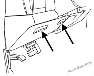
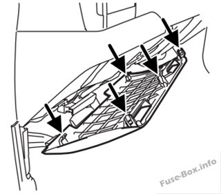
Passenger compartment
The fuse panel is located below and to the left of the steering wheel by the brake pedal behind the panel.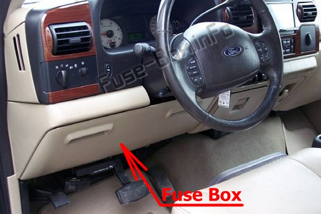
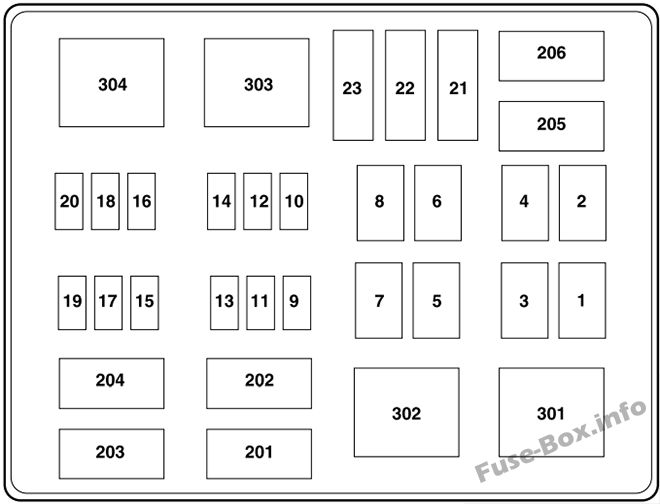
Engine compartment
The power distribution box is located in the engine compartment.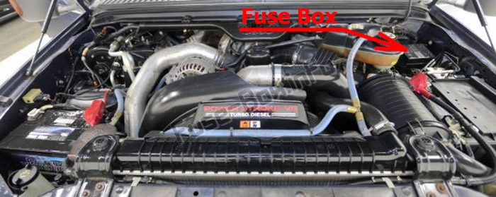
Fuse box diagrams
Fuse box diagrams
2005
Passenger compartment
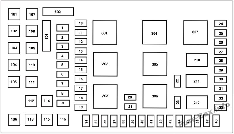
Assignment of the fuses in the Passenger compartment (2005)
| № | Amp Rating | Description |
|---|---|---|
| 1 | 15 A* | Adjustable pedals |
| 2 | 10 A* | Cluster |
| 3 | 10 A* | Upfitter #3 |
| 4 | 20 A* | Power point (Instrument panel) |
| 5 | 10 A* | Upfitter #4 |
| 6 | — | Not used |
| 7 | 30A* | High beam headlamps, Flash-to-pass |
| 8 | 20 A* | Back-up lamps |
| 9 | — | Not used |
| 10 | — | Not used |
| 11 | 20 A* | Radio (Main) |
| 12 | 20 A* | Cigar lighter, OBD II |
| 13 | 5A* | Power mirrors |
| 14 | — | Not used |
| 15 | — | Not used |
| 16 | — | Not used |
| 17 | 15 A* | Exterior lamps |
| 18 | 20 A* | Flasher, Brake On-Off (BOO) lamps |
| 19 | 10 A* | Body Security Module (BSM) (Security) |
| 20 | 15 A* | Trailer tow Electric Brake Controller (EBC) |
| 21 | 20 A* | Heated seats |
| 22 | 20 A* | Engine control |
| 23 | 20 A* | Engine control (gasoline engine only)/Climate control (Diesel engine only) |
| 24 | 15 A* | Tow haul, Blower relay, Electronic Automatic Temperature Control (EATC) |
| 25 | — | Not used |
| 26 | 10 A* | Air bags |
| 27 | 15 A* | Ignition switch RUN feed |
| 28 | 10 A* | Trailer tow EBC logic |
| 29 | 10 A* | Customer access |
| 30 | 15 A* | High beam headlamps |
| 31 | 15 A* | 4×4 |
| 32 | 5A* | Radio (start) |
| 33 | 15 A* | Cluster, 4×4, Wipers |
| 34 | 10 A* | BOO switch (Low current) |
| 35 | 10 A* | Instrument cluster |
| 36 | — | Not used |
| 37 | 15 A* | Horn |
| 38 | 20 A* | Trailer tow park lamps |
| 39 | 15 A* | Heated mirrors |
| 40 | 20 A* | Fuel pump |
| 41 | 10 A* | Instrument cluster |
| 42 | 15 A* | Delayed accessoiy |
| 43 | 10 A* | Fog lamps |
| 44 | — | Not used |
| 45 | 10 A* | Ignition switch RUN/START feed |
| 46 | 10 A* | Left-hand low beam headlamp |
| 47 | 10 A* | Right-hand low beam headlamp |
| 48 | — | Not used |
| 101 | 30A** | Trailer tow EBC |
| 102 | 30A** | BSM (Door locks) |
| 103 | 30A** | Ignition switch |
| 104 | — | Not used |
| 105 | — | Not used |
| 106 | — | Not used |
| 107 | 20A** | Trailer tow battery charge |
| 108 | 30A** | UpFitter #1 |
| 109 | 30A** | UpFitter #2 |
| 110 | 30A** | Ignition switch |
| 111 | — | Not used |
| 112 | 30A** | Power seat (Driver) |
| 113 | 30A** | Starter |
| 114 | 30A** | Power seat (Passenger) |
| 115 | 20A** | UpFitter control |
| 116 | 30A** | Ignition switch |
| 210 | — | Not used |
| 211 | 1/2 ISO relay | Back-up lamps |
| 212 | — | Not used |
| 301 | Full ISO relay | Trailer tow battery charge |
| 302 | Full ISO relay | Powertrain Control Module (PCM) |
| 303 | — | Not used |
| 304 | — | Not used |
| 305 | Full ISO relay | UpFitter control |
| 306 | Full ISO relay | Delayed accessoiy |
| 307 | Full ISO relay | Starter |
| 601 | 30A circuit breaker | Delayed accessoiy, Power windows, Moonroof |
| 602 | — | Not used |
| * Mini fuse ** Cartridge fuse |
Engine compartment
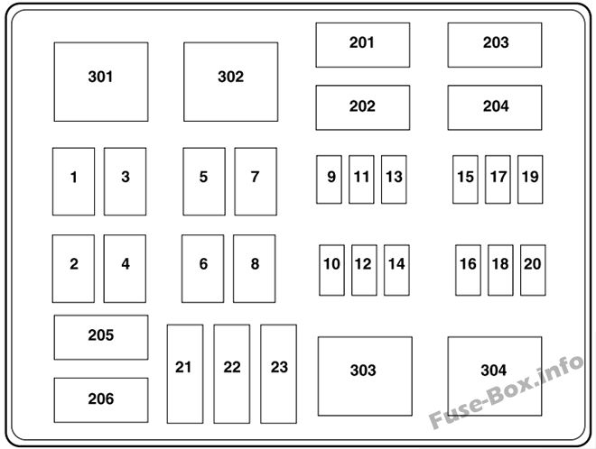
Assignment of the fuses in the Power distribution box (2005)
| № | Amp Rating | Description |
|---|---|---|
| 1 | 30A* | Wipers |
| 2 | 40A* | Blower |
| 3 | 30A* | Electronic Shift on the Fly (ESOF) |
| 4 | — | Not used |
| 5 | 50A* | Injector Driver Module (IDM) (Diesel engine only) |
| 6 | — | Not used |
| 7 | 30A* | Horizontal Fuel Conditioner Module (HFCM) (Diesel engine only) |
| 8 | — | Not used |
| 9 | 20A** | Trailer tow turn signals |
| 10 | 10A** | Powertrain Control Module (PCM) keep alive power, Canister vent solenoid (gasoline engine only) |
| 11 | 10A** | Anti-lock Brake System (ABS) |
| 12 | 2A** | Brake pressure switch |
| 13 | 15 A** | Daytime Running Lamps (DRL) |
| 14 | — | Not used |
| 15 | 15A** | IDM logic (Diesel engine only) |
| 16 | — | Not used |
| 17 | 10A** | A/C clutch |
| 18 | 10A** | IDM relay (Diesel engine only) |
| 19 | — | Not used |
| 20 | 10A** | Trailer tow back-up lamps |
| 21 | — | Not used |
| 22 | 60A*** | ABS (Coils) |
| 23 | 60a*** | ABS (Pump) |
| 201 | 1/2 ISO relay | Trailer tow right turn signal/stop lamp |
| 202 | 1/2 ISO relay | Trailer tow left turn signal/stop lamp |
| 203 | 1/2 ISO relay | A/C clutch |
| 204 | — | Not used |
| 205 | 1/2 ISO relay | DRL #1 |
| 206 | 1/2 ISO relay | DRL #2 |
| 301 | Full ISO relay | DRL #3 |
| 302 | Full ISO relay | HFCM |
| 303 | Full ISO relay | Blower |
| 304 | High-current relay | IDM (Diesel engine only) |
| * Cartdrige Fuse ** Mini Fuses *** Maxi fuse |
2006
Passenger compartment
Assignment of the fuses in the Passenger compartment (2006)
| № | Amp Rating | Description |
|---|---|---|
| 1 | 15 A* | Adjustable pedals |
| 2 | 10 A* | Cluster |
| 3 | 10 A* | Upfitter #3 |
| 4 | 20 A* | Power point (Instrument panel) |
| 5 | 10 A* | Upfitter #4 |
| 6 | — | Not used |
| 7 | 30A* | High beam headlamps, Flash-to-pass |
| 8 | 20 A* | Back-up lamps |
| 9 | — | Not used |
| 10 | — | Not used |
| 11 | 20 A* | Radio (Main) |
| 12 | 20 A* | Cigar lighter, OBD II |
| 13 | 5A* | Power mirrors |
| 14 | — | Not used |
| 15 | — | Not used |
| 16 | — | Not used |
| 17 | 15 A* | Exterior lamps |
| 18 | 20 A* | Flasher, Brake On-Off (BOO) lamps |
| 19 | 10 A* | Body Security Module (BSM) (Security) |
| 20 | 15 A* | Trailer tow Electric Brake Controller (EBC) |
| 21 | 20 A* | Heated seats |
| 22 | 20 A* | Engine control |
| 23 | 20 A* | Engine control (gasoline engine only)/Climate control (Diesel engine only) |
| 24 | 15 A* | Tow haul, Blower relay, Electronic Automatic Temperature Control (EATC) |
| 25 | — | Not used |
| 26 | 10 A* | Airbags |
| 27 | 15 A* | Ignition switch RUN feed |
| 28 | 10 A* | Trailer tow EBC logic |
| 29 | 10 A* | Customer access |
| 30 | 15 A* | High beam headlamps |
| 31 | 15 A* | Starter relay |
| 32 | 5A* | Radio (start) |
| 33 | 15 A* | Cluster, 4×4, Wipers |
| 34 | 10 A* | BOO switch (Low current) |
| 35 | 10 A* | Instrument cluster |
| 36 | — | Not used |
| 37 | 15 A* | Horn |
| 38 | 20 A* | Trailer tow park lamps |
| 39 | 15 A* | Heated mirrors |
| 40 | 20 A* | Fuel pump |
| 41 | 10 A* | Instrument cluster |
| 42 | 15 A* | Delayed accessoiy |
| 43 | 10 A* | Fog lamps |
| 44 | — | Not used |
| 45 | 10 A* | Ignition switch RUN/START feed |
| 46 | 10 A* | Left-hand low beam headlamp |
| 47 | 10 A* | Right-hand low beam headlamp |
| 48 | — | Not used |
| 101 | 30A** | Trailer tow EBC |
| 102 | 30A** | BSM (Door locks) |
| 103 | 30A** | Ignition switch |
| 104 | — | Not used |
| 105 | — | Not used |
| 106 | — | Not used |
| 107 | 20A** | Trailer tow battery charge |
| 108 | 30A** | UpFitter #1 |
| 109 | 30A** | UpFitter #2 |
| 110 | 30A** | Ignition switch |
| 111 | — | Not used |
| 112 | 30A** | Power seat (Driver) |
| 113 | 30A** | Starter |
| 114 | 30A** | Power seat (Passenger) |
| 115 | 20A** | UpFitter control |
| 116 | 30A** | Ignition switch |
| 210 | — | Not used |
| 211 | 1/2 ISO relay | Back-up lamps |
| 212 | — | Not used |
| 301 | Full ISO relay | Trailer tow battery charge |
| 302 | Full ISO relay | Powertrain Control Module (PCM) |
| 303 | — | Not used |
| 304 | — | Not used |
| 305 | Full ISO relay | UpFitter control |
| 306 | Full ISO relay | Delayed accessoiy |
| 307 | Full ISO relay | Starter |
| 601 | 30A circuit breaker | Delayed accessoiy, Power windows, Moonroof |
| 602 | — | Not used |
| * Mini fuse ** Cartridge fuse |
Engine compartment
Assignment of the fuses in the Power distribution box (2006)
| № | Amp Rating | Description |
|---|---|---|
| 1 | 30A* | Wipers |
| 2 | 40 A* | Blower |
| 3 | 30A* | Electronic Shift on the Fly (ESOF) |
| 4 | — | Not used |
| 5 | 50A* | Injector Driver Module (IDM) (Diesel engine only) |
| 6 | — | Not used |
| 7 | 30A* | Horizontal Fuel Conditioner Module (HFCM) (Diesel engine only) |
| 8 | — | Shunt |
| 9 | 20A** | Trailer tow turn signals |
| 10 | 10A** | Powertrain Control Module (PCM) keep alive power, Canister vent solenoid (gasoline engine only) |
| 11 | 10A** | Anti-lock Brake System (ABS) |
| 12 | 2A** | Brake pressure switch |
| 13 | 15A** | Daytime Running Lamps (DRL) |
| 14 | — | Not used |
| 15 | 15A** | IDM logic (Diesel engine only) |
| 16 | — | Not used |
| 17 | 10A** | A/C clutch |
| 18 | 10A** | IDM relay (Diesel engine only) |
| 19 | — | Not used |
| 20 | 10A** | Trailer tow back-up lamps |
| 21 | — | Not used |
| 22 | 60A*** | ABS (Coils) |
| 23 | 60A *** | ABS (Pump) |
| 201 | 1/2 ISO relay | Trailer tow right turn signal/stop lamp |
| 202 | 1/2 ISO relay | Trailer tow left turn signal/stop lamp |
| 203 | 1/2 ISO relay | A/C clutch |
| 204 | — | Not used |
| 205 | 1/2 ISO relay | DRL #1 |
| 206 | 1/2 ISO relay | DRL #2 |
| 301 | Full ISO relay | DRL #3 |
| 302 | Full ISO relay | HFCM |
| 303 | Full ISO relay | Blower |
| 304 | High-current relay | IDM (Diesel engine only) |
| * Cartridge Fuse ** Mini Fuses *** Maxi fuse |
2007
Passenger compartment
Assignment of the fuses in the Passenger compartment (2007)
| № | Amp Rating | Description |
|---|---|---|
| 1 | 15 A* | Adjustable pedals |
| 2 | 10 A* | Cluster |
| 3 | 10 A* | Upfitter #3 |
| 4 | 20 A* | Power point (Instrument panel) |
| 5 | 10 A* | Upfitter #4 |
| 6 | — | Not used |
| 7 | 30A* | High beam headlamps, Flash-to-pass |
| 8 | 20 A* | Back-up lamps |
| 9 | — | Not used |
| 10 | — | Not used |
| 11 | 20 A* | Radio (Main) |
| 12 | 20 A* | Cigar lighter, OBD II |
| 13 | 5A* | Power mirrors |
| 14 | — | Not used |
| 15 | — | Not used |
| 16 | — | Not used |
| 17 | 15 A* | Exterior lamps |
| 18 | 20 A* | Flasher, Brake On-Off (BOO) lamps |
| 19 | 10 A* | Body Security Module (BSM) (Security) |
| 20 | 15 A* | Trailer tow Electric Brake Controller (EBC) |
| 21 | 20 A* | Heated seats |
| 22 | 20 A* | Engine control |
| 23 | 20 A* | Engine control (gasoline engine only)/Climate control (Diesel engine only) |
| 24 | 15 A* | Tow haul, Blower relay, Electronic Automatic Temperature Control (EATC) |
| 25 | — | Not used |
| 26 | 10 A* | Airbags |
| 27 | 15 A* | Ignition switch RUN feed |
| 28 | 10 A* | Trailer tow EBC logic |
| 29 | 10A* | Customer access |
| 30 | 15 A* | High beam headlamps |
| 31 | 15 A* | Starter relay |
| 32 | 5A* | Radio (start) |
| 33 | 15 A* | Cluster, 4×4, Wipers |
| 34 | 10 A* | BOO switch (Low current) |
| 35 | 10 A* | Instrument cluster |
| 36 | — | Not used |
| 37 | 15 A* | Horn |
| 38 | 20 A* | Trailer tow park lamps |
| 39 | 15 A* | Heated mirrors |
| 40 | 20 A* | Fuel pump |
| 41 | 10 A* | Instrument cluster |
| 42 | 15 A* | Delayed accessoiy |
| 43 | 10 A* | Fog lamps |
| 44 | — | Not used |
| 45 | 10 A* | Ignition switch RUN/START feed |
| 46 | 10 A* | Left-hand low beam headlamp |
| 47 | 10 A* | Right-hand low beam headlamp |
| 48 | — | Not used |
| 101 | 30A** | Trailer tow EBC |
| 102 | 30A** | BSM (Door locks) |
| 103 | 30A** | Ignition switch |
| 104 | — | Not used |
| 105 | — | Not used |
| 106 | — | Not used |
| 107 | 20A** | Trailer tow battery charge |
| 108 | 30A** | UpFitter #1 |
| 109 | 30A** | UpFitter #2 |
| 110 | 30A** | Ignition switch |
| 111 | — | Not used |
| 112 | 30A** | Power seat (Driver) |
| 113 | 30A** | Starter |
| 114 | 30A** | Power seat (Passenger) |
| 115 | 20A** | UpFitter control |
| 116 | 30A** | Ignition switch |
| 210 | — | Not used |
| 211 | 1/2 ISO relay | Back-up lamps |
| 212 | — | Not used |
| 301 | Full ISO relay | Trailer tow battery charge |
| 302 | Full ISO relay | Powertrain Control Module (PCM) |
| 303 | — | Not used |
| 304 | — | Not used |
| 305 | Full ISO relay | UpFitter control |
| 306 | Full ISO relay | Delayed accessoiy |
| 307 | Full ISO relay | Starter |
| 601 | 30A circuit breaker | Delayed accessoiy, Power windows, Moonroof |
| 602 | — | Not used |
| * Mini fuse ** Cartridge fuse |
Engine compartment
Assignment of the fuses in the Power distribution box (2007)
| № | Amp Rating | Description |
|---|---|---|
| 1 | 30A* | Wipers |
| 2 | 40A* | Blower |
| 3 | 30A* | Electronic Shift on the Fly (ESOF) |
| 4 | — | Not used |
| 5 | 50A* | Injector Driver Module (IDM) (Diesel engine only) |
| 6 | — | Not used |
| 7 | — | Not used |
| 8 | — | Shunt |
| 9 | 20A** | Trailer tow turn signals |
| 10 | 10A** | Powertrain Control Module (PCM) keep alive power, Canister vent solenoid (gasoline engine only) |
| 11 | 10A** | Anti-lock Brake System (ABS) |
| 12 | 2A** | Brake pressure switch |
| 13 | 15A** | Daytime Running Lamps (DRL) |
| 14 | — | Not used |
| 15 | 15A** | IDM logic (Diesel engine only) |
| 16 | — | Not used |
| 17 | 10A** | A/C clutch |
| 18 | 10A** | IDM relay (Diesel engine only) |
| 19 | — | Not used |
| 20 | 10A** | Trailer tow back-up lamps |
| 21 | — | Not used |
| 22 | 60A*** | ABS (Coils) |
| 23 | 60A*** | ABS (Pump) |
| 201 | 1/2 ISO relay | Trailer tow right turn signal/stop lamp |
| 202 | 1/2 ISO relay | Trailer tow left turn signal/stop lamp |
| 203 | 1/2 ISO relay | A/C clutch |
| 204 | — | Not used |
| 205 | 1/2 ISO relay | DRL #1 |
| 206 | 1/2 ISO relay | DRL #2 |
| 301 | Full ISO relay | DRL #3 |
| 302 | — | Not used |
| 303 | Full ISO relay | Blower |
| 304 | High-current relay | IDM (Diesel engine only) |
| * Cartridge Fuse ** Mini Fuses *** Maxi fuse |


