


Fuse Layout Ford F250 / F350 / F450 / F550 2000-2003
Contents

Cigar lighter (power outlet) fuses in the Ford F-250 / F-350 / F-450 / F-550 are the fuse №3 (Cigar Lighter) in the Instrument panel fuse box, and fuse №10 (Power Point) in the Engine compartment fuse box (2000-2001). 2002-2003 – fuses №4 (Power point – instrument panel) and №12 (Cigar lighter) in the Instrument panel fuse box.
Table of Contents
Fuse box location
Passenger compartment
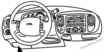
The fuse panel is located below and to the left of the steering wheel by the brake pedal.
1997-2001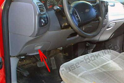
2002-2003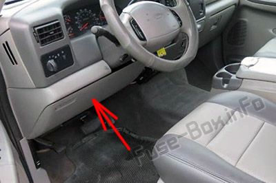
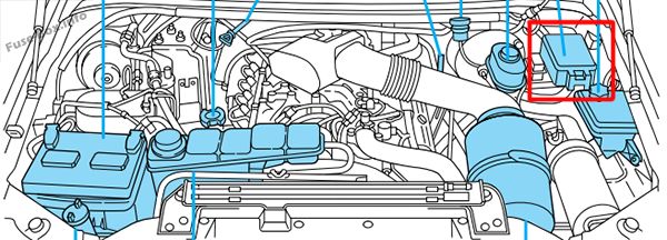
Engine compartment (1997-2001)
The power distribution box, trailer tow and electronic shift on the fly relay blocks are located in the engine compartment near the brake master cylinder.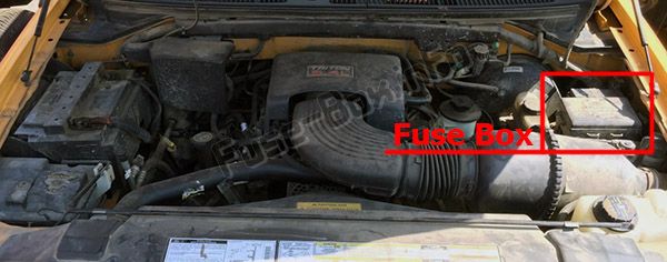
Fuse box diagrams
2000
Passenger compartment
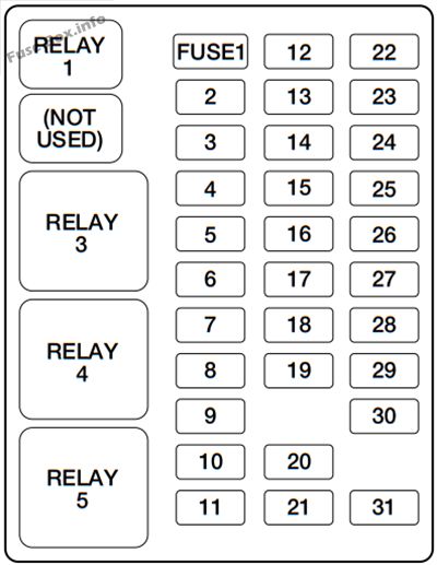
Assignment of the fuses in the Passenger compartment (2000)
| № | Amp Rating | Description |
|---|---|---|
| 1 | 20A | Turn/Hazard Lamps |
| 2 | 10A | Airbag Module |
| 3 | 20A | Cigar Lighter, Data Link Connector |
| 4 | 10A | Glove Box Lamp, Map Lamps, Power Mirrors, Underhood Lamp |
| 5 | — | Not Used |
| 6 | — | Not Used |
| 7 | 5A | Power Window/Lock Swatch Illumination |
| 8 | 5A | Radio, Headlamp Switch Illumination |
| 9 | — | Not Used |
| 10 | 15A | Dual Fuel Tanks |
| 11 | 30A | Wiper Motor, Wiper Run/Park Relay Coil, Wiper Hi/LO Relay Coil, Washer Pump Relay Coil |
| 12 | 15A | Horn |
| 13 | 20A | Stop Lamps, Center High-mount Stop Lamp, Trailer Tow Stop Lamp, Speed Control |
| 14 | 10A | Dome Lamp, Cargo Lamp, Courtesy Lamps, Running Board Lamps |
| 15 | 5A | Stop Lamp Switch (Logic): Generic Electronic Module (GEM), Powertrain Control Module (PCM), Four Wheel Anti-lock Brake System (4WABS) Module, Brake Shift Interlock, Cluster and PCM Keep Alive Memory |
| 16 | 15A | Instrument Cluster, Hi-beam Headlamps |
| 17 | — | Not Used |
| 18 | — | Not Used |
| 19 | 10A | Auxiliary Powertrain Control Module (APCM) (Diesel only), Instrument Cluster, GEM Module, Overdrive Cancel Switch, Idle Validation Switch (Diesel only), Overhead Console, Diesel PCM via Clutch |
| 20 | 15A | Starter Motor Relay Coil, Clutch Switch |
| 21 | — | Not Used |
| 22 | 10A | Air Bag Module, Passenger Air Bag Activation/Deactivation Switch, Blower Motor Relay Coil |
| 23 | — | Not Used |
| 24 | 10A | A/C Clutch, Blend Door Actuator, Trailer Tow Battery Charge Relay Coil, Four Wheel Anti-Lock Brake System (4WABS), Turn Signal |
| 25 | — | Not Used |
| 26 | — | Not Used |
| 27 | 10A | Ignition Run Power Feed (Customer Access) |
| 28 | 10A | Brake Shift Interlock, DRL Relay Coil, Speed Control Module, Backup Lamps, Trailer Tow Backup Lamp Relay Coil, Electronic Shift On The Fly Hub Lock Solenoid, Vacuum Pump Motor |
| 29 | 5A | Instrument Cluster (Charge and Airbag Warning Lamps) |
| 30 | 30A | PCM Relay Coil, Ignition Coil (Gasoline only), Fuel Heater (Diesel only), Wastegate Solenoid (Diesel only), Injector Driver Module Relay Coil (Diesel only) |
| 31 | — | Not Used |
| Relay 1 | — | Interior Lamp Relay |
| Relay 2 | — | Not Used |
| Relay 3 | — | Horn |
| Relay 4 | — | Power Window One Touch Down Relay |
| Relay 5 | — | Accessoiy Delay Relay |
Engine compartment
Assignment of the fuses in the Power distribution box (2000)
| № | Amp Rating | Description |
|---|---|---|
| 1 | 7.5A * | Trailer Tow Left Stop/Turn Lamp |
| 2 | 10 A* | Washer Pump |
| 3 | 7.5 A* | Trailer Tow Right Stop/Turn Lamp |
| 4 | 20 A* | Trailer Tow Backup Lamps, Trailer Tow Park Lamps |
| 5 | 20A* (Gasoline only) 5A* (Diesel only) |
Gasoline only-PCM, Fuel Pump Relay Coil, Mass Air Flow Sensor, Fuel Injectors Diesel only-Dual Alternator “A” Field |
| 6 | 10 A* | Gasoline only-A/C (CASS) Diesel only-Single or Dual Alternator “A” Field, Regulator |
| 7 | 20A* (Gasoline only) 5A* (Diesel only) |
Gasoline only-Vapor Management Valve, HEGO Sensors, Intake Manifold Communication Control, EVR Solenoid, PCM, Canister Vent Solenoid Diesel only-Dual Alternator “A” Field |
| 8 | 15 A* | Trailer Tow Electronic Brake Illumination, Park Lamps, Trailer Tow Park Lamp Relay Coil |
| 9 | 10 A* | Left Headlamp (Low Beam) |
| 10 | 20 A* | Power Point |
| 11 | 10 A* | Right Headlamp (Low Beam) |
| 12 | 15 A* | Daytime Running Lamps (DRL) Resistor |
| 13 | 30A** | Multi-function Switch, Headlamps |
| 14 | 60A** | Anti-Lock Brake System |
| 15 | — | Not Used |
| 16 | 30A** | Trailer Tow Batteiy Charge |
| 17 | 30A** | Electronic Shift On The Fly Relay, Transfer Case Shift Motor |
| 18 | 30A** | Power Seat |
| 19 | 20A** | Fuel Pump Motor, PCM |
| 20 | 50A** | Ignition Switch (B4 & B5) |
| 21 | 50A** | Ignition Switch (B1 & B3) |
| 22 | 50A** | Junction Box Battery Feed |
| 23 | 40A** | Blower Motor |
| 24 | 30A** (Gasoline only) 20A** (Diesel only) |
PCM Power |
| 25 | 30a*** | Power Windows |
| 26 | 20A** | If equipped with Remote Keyless Entry-Driver Door Unlock Relay Coil, All Door Unlock Relay Coil, All Door Lock Relay Coil, Park Lamp Flash Relay, If not equipped with Remote Keyless Entry-Power Door Lock Motors |
| 27 | – (Gasoline only) 30A** (Diesel only) |
Gasoline only-Not Used Diesel only-injector Driver Module |
| 28 | 30A** | Trailer Tow Electronic Brake Controller |
| 29 | 20A** | Radio |
| 30 | — | PCM Power Relay |
| 31 | — | Blower Motor Relay |
| 32 | — | A/C CASS (Gasoline only), Injector Driver Module Power Relay (Diesel only) |
| 33 | — | Washer Pump Relay |
| 34 | — | Windshield Wiper Park/Run Relay |
| 35 | — | Windshield Wiper HI/LO Relay |
| 36 | — | A/C Clutch Diode |
| 37 | — | PCM Diode |
| 38 | — | Trailer Tow Backup Lamp Relay |
| 39 | — | Trailer Tow Batteiy Charge Relay |
| 40 | — | Electronic Shift On The Fly Relay #1 |
| 41 | — | Electronic Shift On The Fly Relay #2 |
| * Mini Fuses ** Maxi Fuses *** Circuit Breaker |
2001
Passenger compartment
Assignment of the fuses in the Passenger compartment (2001)
| № | Amp Rating | Description |
|---|---|---|
| 1 | 20A | Turn/Hazard Lamps |
| 2 | — | Not Used |
| 3 | 20A | Cigar Lighter, Data Link Connector |
| 4 | 10A | Glove Box Lamp, Map Lamps, Power Mirrors, Underhood Lamp |
| 5 | — | Not Used |
| 6 | — | Not Used |
| 7 | 5A | Power Window/Lock Switch Illumination |
| 8 | 5A | Radio, Headlamp Switch Illumination |
| 9 | — | Not Used |
| 10 | 15A | Dual Fuel Tanks |
| 11 | 30A | Wiper Motor, Wiper Run/Park Relay Coil, Wiper Ili/LO Relay Coil, Washer Pump Relay Coil |
| 12 | 15A | Horn |
| 13 | 20A | Stop Lamps, Center Iligh-mount Stop Lamp, Trailer Tow Stop Lamp, Speed Control |
| 14 | 10A | Dome Lamp, Cargo Lamp, Courtesy Lamps, Running Board Lamps |
| 15 | 5A | Stop Lamp Switch (Logic): Generic Electronic Module (GEM), Powertrain Control Module (PCM), Four Wheel Anti-lock Brake System (4WABS) Module, Brake Shift Interlock, Cluster and PCM Keep Alive Memory |
| 16 | 15A | Instrument Cluster, Hi-beam Headlamps |
| 17 | — | Not Used |
| 18 | 5A | Audio |
| 19 | 10A | Auxiliary Pow r ertrain Control Module (APCM) (Diesel only), Instrument Cluster, GEM Module, Overdrive Cancel Switch, Idle Validation Switch (Diesel only), Overhead Console, Diesel PCM via Clutch |
| 20 | 15A | Starter Motor Relay Coil, Clutch Switch |
| 21 | — | Not Used |
| 22 | 10A | Passenger Air Bag Activation/Deactivation Switch, Blow r er Motor Relay Coil |
| 23 | 10A | Air Bag Module |
| 24 | 10A | A/C Clutch, Blend Door Actuator, Trailer Tow Battery Charge Relay Coil, Four Wheel Anti-Lock Brake System (4WABS), Turn Signal |
| 25 | — | Not Used |
| 26 | — | Not Used |
| 27 | 10A | Ignition Run Power Feed (Customer Access) |
| 28 | 15A | Brake Shift Interlock, DRL Relay Coil, Speed Control Module, Backup Lamps, Trailer Tow Backup Lamp Relay Coil, Electronic Shift On The Fly Hub Lock Solenoid, Vacuum Pump Motor |
| 29 | 5A | Instrument Cluster (Charge and Airbag Warning Lamps) |
| 30 | 30A | PCM Relay Coil, Ignition Coil (Gasoline only), Fuel Heater (Diesel only), Wastegate Solenoid (Diesel only), Injector Driver Module Relay Coil (Diesel only) |
| 31 | 5A | Fog Lamp Switch |
| Relay 1 | — | Interior Lamp Relay |
| Relay 2 | — | Not Used |
| Relay 3 | — | Horn |
| Relay 4 | — | Power Window One Touch Down Relay |
| Relay 5 | — | Accessory Delay Relay |
Engine compartment
Assignment of the fuses in the Power distribution box (2001)
| № | Amp Rating | Description |
|---|---|---|
| 1 | 7.5A * | Trailer Tow Left Stop/Turn Lamp |
| 2 | 10 A* | Washer Pump |
| 3 | 7.5 A* | Trailer Tow Right Stop/Turn Lamp |
| 4 | 20A* | Trailer Tow Backup Lamps, Trailer Tow Park Lamps |
| 5 | 20A* (Gasoline only) 5A* (Diesel only) |
Gasoline only-PCM, Fuel Pump Relay Coil, Mass Air Flow Sensor, Fuel Injectors Diesel only-Dual Alternator “A” Field |
| 6 | 10 A* | Gasoline only-A/C (CASS) Diesel only-Single or Dual Alternator “A” Field, Regulator |
| 7 | 20A* (Gasoline only) 5A* (Diesel only) |
Gasoline only-Vapor Management Valve, HEGO Sensors, Intake Manifold Communication Control, EVR Solenoid, PCM, Canister Vent Solenoid Diesel only-Dual Alternator “A” Field |
| 8 | 15A* | Trailer Tow Electronic Brake Illumination, Park Lamps, Trailer Tow Park Lamp Relay Coil |
| 9 | 10 A* | Left Headlamp (Low Beam) |
| 10 | 20A* | Power Point |
| 11 | 10 A* | Right Headlamp (Low Beam) |
| 12 | 15A* | Daytime Running Lamps (DRL) Resistor, Fog Lamps |
| 13 | 30A** | Multi-function Switch, Headlamps |
| 14 | 60A** | Anti-Lock Brake System |
| 15 | 30A** | Heated Seats |
| 16 | 30A** | Trailer Tow Battery Charge |
| 17 | 30A** | Electronic Shift On The Fly Relay, Transfer Case Shift Motor |
| 18 | 30A** | Power Seat, Adjustable Pedals |
| 19 | 20A** | Fuel Pump Motor, PCM |
| 20 | 50A** | Ignition Switch (B4 & B5) |
| 21 | 50A** | Ignition Switch (B1 & B3) |
| 22 | 50A** | Junction Box Battery Feed |
| 23 | 40A** | Blower Motor |
| 24 | 30A** (Gasoline only) 20A** (Diesel only) |
PCM Power |
| 25 | 30a*** | Power Windows |
| 26 | 20A** | If equipped with Remote Keyless Entry-Driver Door Unlock Relay Coil, All Door Unlock Relay Coil, All Door Lock Relay Coil, Park Lamp Flash Relay, If not equipped with Remote Keyless Entry-Power Door Lock Motors |
| 27 | – (Gasoline only) 30A** (Diesel only) |
Gasoline only-Not Used Diesel only-injector Driver Module |
| 28 | 30A** | Trailer Tow Electronic Brake Controller |
| 29 | 20A** | Radio |
| 30 | — | PCM Pow er Relay |
| 31 | — | Blow r er Motor Relay |
| 32 | — | A/C CASS (Gasoline only), Injector Driver Module Power Relay (Diesel only) |
| 33 | — | Washer Pump Relay |
| 34 | — | Windshield Wiper Park/Run Relay |
| 35 | — | Windshield Wiper HI/LO Relay |
| 36 | — | A/C Clutch Diode |
| 37 | — | PCM Diode |
| 38 | — | Trailer Tow Backup Lamp Relay |
| 39 | — | Trailer Tow Battery Charge Relay |
| 40 | — | Electronic Shift On The Fly Relay #1 |
| 41 | — | Electronic Shift On The Fly Relay #2 |
| * Mini Fuses ** Maxi Fuses *** Circuit Breaker |
2002
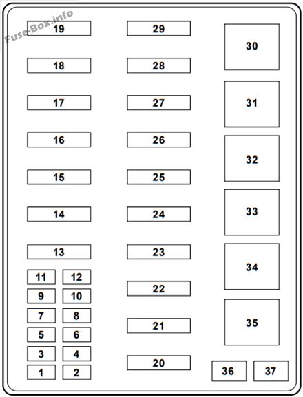
Passenger compartment
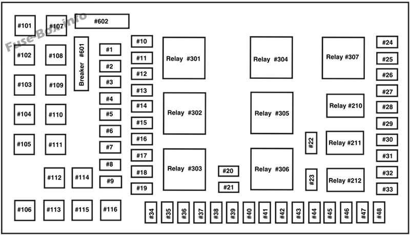
Assignment of the fuses in the Passenger compartment / Power distribution box (2002)
| № | Amp Rating | Description |
|---|---|---|
| 1 | 15 A* | Adjustable pedals |
| 2 | — | Not used |
| 3 | — | Not used |
| 4 | 20 A* | Power point – instrument panel |
| 5 | — | Not used |
| 6 | 20 A* | Trailer tow turn/stop relay |
| 7 | 30A* | High beam headlamps/Flash to pass |
| 8 | — | Not used |
| 9 | — | Not used |
| 10 | 10 A* | A/C clutch |
| 11 | 20 A* | Radio (main) |
| 12 | 20 A* | Cigar lighter / OBD II |
| 13 | 5A* | Power mirrors/switches |
| 14 | 15 A* | Daytime running lamps (DRL) |
| 15 | — | Not used |
| 16 | — | Not used |
| 17 | 15 A* | Exterior lamps |
| 18 | 20 A* | Turn lamps/Brake on-off swatch (high) |
| 19 | 10 A* | Body security module/4×4 module |
| 20 | — | Not used |
| 21 | — | Not used |
| 22 | 20 A* | Engine control |
| 23 | 20 A* | Engine control (gasoline engine only) |
| 24 | 15 A* | Not used (spare) |
| 25 | 10 A* | 4-Wheel Anti-lock Brake System (4WABS) module |
| 26 | 10 A* | Air bags |
| 27 | 15 A* | Ignition switch Run feed |
| 28 | 10 A* | EATC module/Front blower relay coil |
| 29 | 10 A* | Customer access |
| 30 | 15 A* | Highbeam headlamps |
| 31 | 15 A* | Clutch interlock switch (manual transmissions only), Transmission range sensor (automatic transmissions only) then to starter relay coil (all transmissions) |
| 32 | 5A* | Radio (start) |
| 33 | 15 A* | Front wiper |
| 34 | 10 A* | Brake on-off switch |
| 35 | 10 A* | Instrument cluster |
| 36 | 10 A* | PCM Keep-Alive |
| 37 | 15 A* | Horn |
| 38 | 20 A* | Trailer tow park lamps and backup lamps |
| 39 | — | Not used |
| 40 | 20 A* | Fuel pump |
| 41 | 10 A* | Instrument cluster |
| 42 | 15 A* | Delayed accessory |
| 43 | 10 A* | Fog lamps |
| 44 | — | Not used |
| 45 | 10 A* | Ignition switch Run/Start feed |
| 46 | 10 A* | Left-hand lowbeam |
| 47 | 10 A* | Right-hand lowbeam |
| 48 | — | Not used |
| 101 | 30A** | Trailer tow electric brake |
| 102 | 30A** | Door locks/Body security module |
| 103 | 50A** | Ignition switch |
| 104 | — | Not used |
| 105 | 30A** | Injector driver module (Diesel engine only) |
| 106 | 30A** | Front wiper main |
| 107 | 40A** | Front blower motor |
| 108 | — | Not used |
| 109 | 30A** | Heated seats |
| 110 | 50A** | Ignition switch |
| 111 | 30A** | 4WD/Shift on the fly |
| 112 | 30A** | Left-hand power seats |
| 113 | 30A** | Starter motor |
| 114 | 30A** | Right-hand power seats |
| 115 | 20A** | Trailer tow battery charge |
| 116 | 30A** | Ignition switch |
| 601 | 30A CB*** | Door window motors |
| 602 | 60A** | 4WABS module |
| 210 | — | Not used |
| 211 | — | Not used |
| 212 | — | Not used |
| 301 | — | Front blower motor relay |
| 302 | — | Powertrain (EEC) relay |
| 303 | — | Injector driver module relay (Diesel engine only) |
| 304 | — | Not used |
| 305 | — | Trailer tow battery charge relay |
| 306 | — | Delayed accessory relay |
| 307 | — | Starter relay |
| * Mini Fuses ** Maxi Fuses *** Circuit Breaker |
2003
Passenger compartment
Assignment of the fuses in the Passenger compartment / Power distribution box (2003)
| № | Amp Rating | Description |
|---|---|---|
| 1 | 15 A* | Adjustable pedals |
| 2 | 20 A* | Not used |
| 3 | 20 A* | Not used |
| 4 | 20 A* | Power point – instrument panel |
| 5 | 20 A* | Not used |
| 6 | 20 A* | Trailer tow turn/stop relay |
| 7 | 30 A* | High beam headlamps/Flash to pass |
| 8 | — | Not used |
| 9 | 20 A* | Not used |
| 10 | 10 A* | A/C clutch |
| 11 | 20 A* | Radio (main) |
| 12 | 20 A* | Cigar lighter/OBD II |
| 13 | 5A* | Power mirrors/switches |
| 14 | 15 A* | Daytime running lamps (DRL) |
| 15 | 10 A* | Not used |
| 16 | 15 A* | Not used |
| 17 | 15 A* | Exterior lamps |
| 18 | 20 A* | Turn lamps/Brake on-off switch (high) |
| 19 | 10 A* | Body security module/4×4 module |
| 20 | — | Not used |
| 21 | 25 A* | Not used |
| 22 | 20 A* | Engine control |
| 23 | 20 A* | Engine control (gasoline engine only) |
| 24 | 15 A* | Not used |
| 25 | 10 A* | 4-Wheel Anti-lock Brake System (4WABS) module |
| 26 | 10 A* | Air bags |
| 27 | 15 A* | Ignition switch Run feed |
| 28 | 10 A* | EATC module/Front blower relay coil |
| 29 | 10 A* | Customer access |
| 30 | 15 A* | Highbeam headlamps |
| 31 | 15A* | Clutch interlock switch (manual transmissions only), Transmission range sensor (automatic transmissions only) then to starter relay coil (all transmissions) |
| 32 | 5A* | Radio (start) |
| 33 | 15 A* | Front wiper |
| 34 | 10 A* | Brake on-off switch |
| 35 | 10 A* | Instrument cluster |
| 36 | 10 A* | PCM Keep-Alive |
| 37 | 15 A* | Horn |
| 38 | 20 A* | Trailer tow park lamps and backup lamps |
| 39 | — | Not used |
| 40 | 20 A* | Fuel pump |
| 41 | 10 A* | Instrument cluster |
| 42 | 15 A* | Delayed accessory |
| 43 | 10 A* | Fog lamps |
| 44 | 10 A* | Not used |
| 45 | 10 A* | Ignition switch Run/Start feed |
| 46 | 10 A* | Left-hand lowbeam |
| 47 | 10 A* | Right-hand lowbeam |
| 48 | 10 A* | Not used |
| 101 | 30A** | Trailer tow electric brake |
| 102 | 30A** | Door locks/Body security module |
| 103 | 50A** | Ignition switch |
| 104 | 40A** | Not used |
| 105 | 30A** | Injector driver module (Diesel engine only) |
| 106 | 30A** | Front wiper main |
| 107 | 40A** | Front blower motor |
| 108 | 40A** | Not used |
| 109 | 30A** | Heated seats |
| 110 | 50A** | Ignition switch |
| 111 | 30A** | 4WD/Shift on the fly |
| 112 | 30A** | Left-hand power seats |
| 113 | 30A** | Starter motor |
| 114 | 30A** | Right-hand power seats |
| 115 | 20A** | Trailer tow battery charge |
| 116 | 30A** | Ignition switch |
| 601 | 30A CB*** | Door window motors |
| 602 | 60A** | 4WABS module |
| 210 | — | Not used |
| 211 | — | Not used |
| 212 | — | Not used |
| 301 | — | Front blower motor relay |
| 302 | — | Powertrain (EEC) relay |
| 303 | — | Injector driver module relay (Diesel engine only) |
| 304 | — | Not used |
| 305 | — | Trailer tow battery charge relay |
| 306 | — | Delayed accessory relay |
| 307 | — | Starter relay |
| * Mini Fuses ** Maxi Fuses *** Circuit Breaker |


