
See other Ford Transit:
Fuse Layout Ford Transit 2019-2020…
Contents
![]()
![]()
Table of Contents
Fuses Box Location
Fuses Box Location
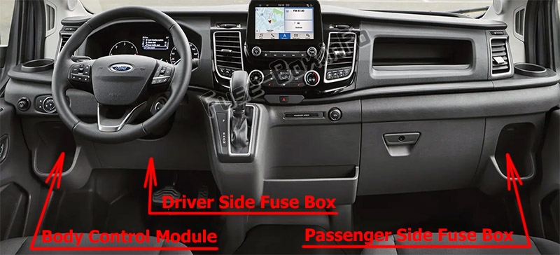
Passenger Compartment
There are four fuse boxes:
- Driver Side Fuse Box is behind the removable trim panel below the steering wheel;
- Passenger Side Fuse Box is behind the lid in the right storage compartment;
- Body Control Module is behind the lid in the left storage compartment;
- Pre-fuse Box is located under the driver’s seat.
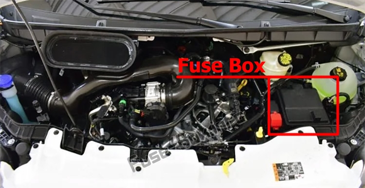
Engine Compartment
Fuse Box Diagrams
Fuse Box Diagrams
Pre-fuse Box
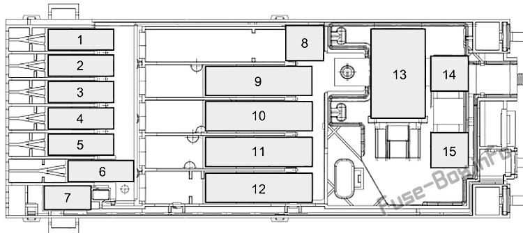
Assignment of the fuses in the Pre-fuse Box
| № | Amp | Description |
|---|---|---|
| 1 | 125A | Body control module. |
| 2 | 80A | Electronic power assist steering. |
| 3 | 150A | Positive temperature coefficient heater. |
| 4 | – | Not used. |
| 5 | – | Not used. |
| 6 | 150A | Passenger compartment fuse box. |
| 7 | 60A | Camper. |
| 8 | – | Not used. |
| 9 | 500A | Starter motor. Alternator. |
| 10 | 300A | Engine compartment fuse box. |
| 11 | 250A | Dual generators. |
| 12 | 150A | Driver compartment fuse box. |
| 13 | 190A | Load shed relay. |
| 14 | 175A | Auxiliary power point 1. |
| 15 | 60A | Auxiliary power point 2. |
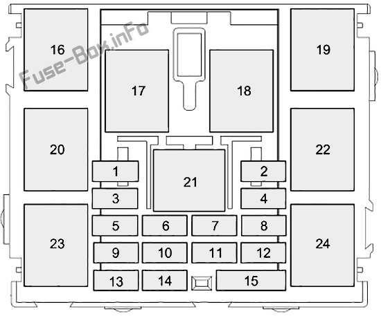
Driver Side Fuse Box
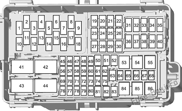
Assignment of the fuses in the Driver Side Fuse Box
| № | Amp | Description |
|---|---|---|
| 1 | 5A | USB port. |
| 2 | – | Not used. |
| 3 | 5A | USB port. |
| 4 | – | Not used. |
| 5 | – | Not used. |
| 6 | – | Not used. |
| 7 | – | Not used. |
| 8 | – | Not used. |
| 9 | 10A | Heated exterior mirrors. |
| 10 | 5A | Cooling fan. |
| 11 | – | Not used. |
| 12 | – | Not used. |
| 13 | – | Not used. |
| 14 | – | Not used. |
| 15 | – | Not used. |
| 16 | 5A | Rain sensor. |
| 17 | – | Not used. |
| 18 | – | Not used. |
| 19 | – | Not used. |
| 20 | – | Not used. |
| 21 | 20A | Heated rear window. |
| 22 | 20A | Heated rear window. |
| 23 | 20A | Auxiliary power point. |
| 24 | 20A | Auxiliary power point. |
| 25 | – | Not used. |
| 26 | 25A | Windshield wiper motor. |
| 27 | – | Not used. |
| 28 | 30A | Modified vehicle connections. |
| 29 | 20A | Fuel fired heater. |
| 30 | 30A | Power running boards. |
| 31 | – | Not used. |
| 32 | – | Not used. |
| 33 | – | Not used. |
| 34 | – | Not used. |
| 35 | – | Not used. |
| 36 | – | Not used. |
| 37 | – | Not used. |
| 38 | – | Not used. |
| 39 | – | Not used. |
| 40 | – | Not used. |
| 41 | 25A | Load shed relay. |
| 42 | 40A | Starter relay. |
| 43 | 40A | Upfitter relay. |
| 44 | 40A | Starter relay. |
| 45 | 10A | Upfitter interface module. |
| 46 | – | Not used. |
| 47 | – | Not used. |
| 48 | 5A | Modified vehicle connections. |
| 49 | 10A | Brake pedal switch. |
| 50 | 30A | Passenger power seat. |
| 51 | 40A | Modified vehicle connections. |
| 52 | 30A | Driver power seat. |
| 53 | 60A | Battery. |
| 54 | 60A | Power inverter. |
| 55 | 50A | Body control module. |
| 56 | 10A | Modified vehicle connections. |
| 57 | – | Not used. |
| 58 | 10A | Connector camper body interface. Upfitter interface. Secondary junction box. |
| 59 | 10A | Rear climate control. Front view camera. Rear view camera. Adaptive cruise control module. Blind spot information system. |
| 60 | 10A | Trailer brake control module. |
| 61 | – | Not used. |
| 62 | 15A | Enhanced cut off relay system module. |
| 63 | 20A | Auxiliary power point. |
| 64 | 40A | Modified vehicle connections. |
| 65 | – | Not used. |
| 66 | 10A | Enhanced cut off relay system. Camper. Load shed relay. |
| 67 | – | Not used. |
| 68 | 5A | Trailer tow module. |
| 69 | 5A | Steering wheel module. |
| 70 | – | Not used. |
| 71 | 10A | Passenger heated seat. |
| 72 | 10A | Driver heated seat. |
| 73 | 20A | Adaptive front lighting module. Headlamp leveling. |
| 74 | – | Not used. |
| 75 | 20A | Engine compartment fuse box. |
| 76 | 10A | Power sliding door control switch. |
| 77 | 5A | Headlamp switch. |
| 78 | 7.5A | Modified vehicle connections. |
| 79 | 5A | Driver compartment fuse box relay. |
| 80 | – | Not used. |
| 81 | 40A | Trailer tow module. |
| 82 | 30A | Power sliding door. |
| 83 | 30A | Trailer brake control module. |
| 84 | 50A | Body control module. |
| 85 | 30A | Power sliding door. |
| 86 | 50A | Body control module. |
Passenger Side Fuse Box
Assignment of the fuses in the Passenger Side Fuse Box
| № | Amp | Description |
|---|---|---|
| 1 | – | Relay 2. |
| 2 | – | Relay 3. |
| 3 | – | Relay 1. |
| 4 | – | Relay 4. |
| 5 | – | Relay 5. |
| 6 | – | Not used. |
| 7 | – | Not used. |
| 8 | – | Relay 7. |
| 9 | – | Relay 8. |
| 10 | – | Not used. |
| 11 | – | Not used. |
| 12 | – | Relay 9. |
| 13 | – | Relay 6. |
| 14 | 5A | Ignition. |
| 15 | 5A | Power supply. |
| 16 | – | Auxiliary switch 3 relay. |
| 17 | – | Auxiliary switch 3 relay. |
| 18 | – | Auxiliary switch 3 relay. |
| 19 | – | Auxiliary switch 4 relay. |
| 20 | – | Auxiliary switch 5 relay. |
| 21 | – | Auxiliary fuse box relay. |
| 22 | – | Auxiliary switch 7 relay. |
| 23 | – | Auxiliary switch 8 relay. |
| 24 | – | Auxiliary switch 9 relay. |
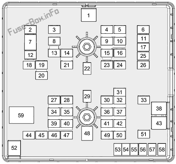
Body Control Module
Assignment of the fuses in the Body Control Module
| № | Amp | Description |
|---|---|---|
| 1 | – | Not used. |
| 2 | 10A | Power inverter. |
| 3 | 7.5A | Power window switch. Power exterior mirrors. |
| 4 | 20A | Not used. |
| 5 | – | Not used. |
| 6 | 10A | Not used. |
| 7 | 10A | Not used. |
| 8 | 5A | Anti-theft alarm horn. |
| 9 | 5A | Intrusion sensor. Rear air conditioning. |
| 10 | – | Not used. |
| 11 | – | Not used. |
| 12 | 7.5A | Climate control. |
| 13 | 7.5A | Data link connector. Steering column. Instrument cluster. |
| 14 | 15A | Battery energy control module – MHEV. |
| 15 | 15A | SYNC 3 module. |
| 16 | – | Not used. |
| 17 | 7.5A | Not used. |
| 18 | 7.5A | Not used. |
| 19 | 5A | Not used. |
| 20 | 5A | Ignition switch. |
| 21 | 5A | Positive temperature coefficient heater control. |
| 22 | 5A | Pedestrian alert control module. |
| 23 | 30A | Not used. |
| 24 | 30A | Not used. |
| 25 | 20A | Not used. |
| 26 | 30A | Not used. |
| 27 | 30A | Not used. |
| 28 | 30A | Not used. |
| 29 | 15A | Not used. |
| 30 | 5A | Not used. |
| 31 | 10A | Data link connector. Remote key receiver. |
| 32 | 20A | Radio. Telematics module. |
| 33 | – | Not used. |
| 34 | 30A | Message center. Positive temperature coefficient heater. Direct current/Alternating current inverter. Lane keeping system camera. Parking aid. Steering column. |
| 35 | 5A | Not used. |
| 36 | 15A | Parking aid. Lane keeping system camera. Steering column control module. |
| 37 | 20A | Not used. |
| 38 | 30A | Power windows. |
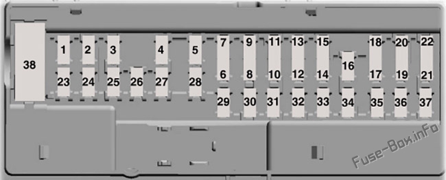
Engine Compartment Fuse Box
Assignment of the fuses in the engine compartment
| № | Amp | Description |
|---|---|---|
| 1 | 50A | Wipers. |
| 2 | 40A | All-Wheel Drive. |
| 3 | 40A | Right-hand heated windshield element. |
| 4 | 30A | Parking lamps. |
| 5 | 10A | Reversing lamp. |
| 6 | – | Not used. |
| 7 | 40A | Front blower motor. |
| 8 | 40A | Left-hand heated windshield element. |
| 9 | 15A | Rear door latch. |
| 10 | – | Not used. |
| 11 | 40A | Auxiliary power point. USB port. |
| 12 | 20A | Horn. |
| 13 | 10A | Selective catalytic reduction system. |
| 14 | 15A | Vehicle power 5. |
| 15 | – | Not used. |
| 16 | – | Not used. |
| 17 | 10A | Right-hand high-intensity discharge headlamps. |
| 18 | 40A | Rear window defroster. |
| 19 | 20A | Front fog lamps. |
| 20 | 10A | Power folding mirrors. |
| 21 | 15A | Vehicle power 4. |
| 22 | 40A | Rear blower motor. |
| 23 | 20A | Fuel pump. |
| 24 | 40A | Run/Start relay. |
| 25 | 40A | Auxiliary power points. |
| 26 | 10A | Left-hand high-intensity discharge headlamps. |
| 27 | – | Not used. |
| 28 | 20A | Vehicle power 1. |
| 29 | 40A | Fuel filter heater. |
| 30 | 15A | Coolant pump. |
| 31 | 5A | Anti-lock brake system. |
| 32 | 15A | Transmission control module. |
| 33 | 30A | Starter motor. |
| 34 | 15A | Selective catalytic reduction system. |
| 35 | 15A | Vehicle power 2. |
| 36 | 5A | Engine coolant bypass valve. |
| 37 | 5A | Glow plugs. Powertrain control module. |
| 38 | 60A | Cooling fan. |
| 39 | 15A | Selective catalytic reduction system. |
| 40 | 10A | Vehicle power 3. |
| 41 | 10A | Controller glow plug. |
| 42 | 15A | Transmission control unit. |
| 43 | 60A | Anti-lock brake system pump. |
| 44 | 25A | Cooling fan. |
| 45 | 30A | Trailer socket. |
| 46 | 40A | Glow plugs. |
| 47 | 40A | Glow plugs. |
| 48 | 50A | Cooling fan. |
| 49 | 15A | Nitrogen oxides sensor. |
| 50 | 5A | Closed crankcase ventilation heater. |
| 51 | 10A | Air conditioning clutch. |
| 52 | 50A | Cooling fan. |
| 53 | – | Not used. |
| 54 | 20A | Backup alarm. |
| 55 | 25A | Transmission oil pump. |
| 56 | 20A | Fuel fired booster heater. |
| 57 | 25A | Anti-lock brake system with electronic stability control. |
| 58 | 30A | Trailer socket. |
| 59 | – | Cooling fan relay. |


