
See other Ford Transit Custom:
Fuse Layout Ford Transit Custom / Tourneo Custom 2012-2016
Contents
![]()
![]()
Table of Contents
Fuses Box Location
Fuses Box Location
Passenger Compartment
Two fuse boxes are located behind the removable trim panels – the Fuse Box is on the right, and the Body Control Module is on the left (on vehicles with right-hand drive – on the contrary).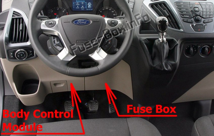
Pre-fuse Box
This is located under the driver’s seat.
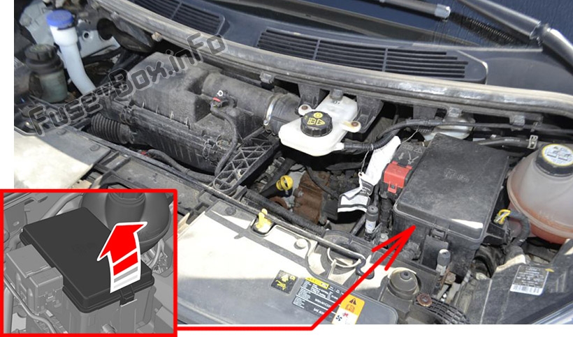
Engine Compartment
Fuse Box Diagrams
Fuse Box Diagrams
Pre-fuse Box
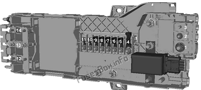
Assignment of the fuses in the Pre-fuse Box
| № | Amp | Description |
|---|---|---|
| F1 | 350A | Alternator. Starter motor. Battery junction box. |
| F2 | 100A | Auxiliary junction box. |
| F3 | – | Not used. |
| F4 | 200A | Auxiliary junction box. |
| F5 | 100A | Auxiliary junction box. |
| F6 | 80A | Electric booster heater. |
| F7 | 80A | Auxiliary junction box. |
| F8 | 100A | Battery junction box. |
| F9 | 100A | Auxiliary junction box. |
| F10 | 60A | Body control module 1. |
| F11 | 60A | Body control module 2. |
| F12 | 60A | Customer access. |
| F13 | – | Not used. |
| F14 | 60A | Customer access. |
Passenger Compartment Fuse Box
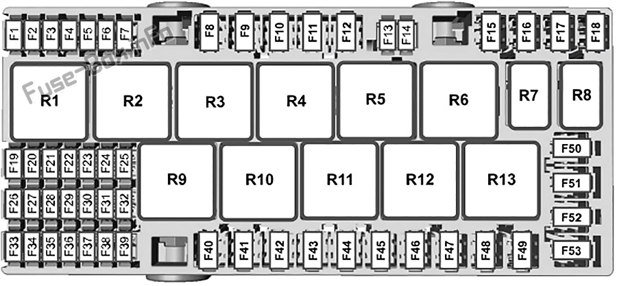
Assignment of the fuses in the instrument panel
| № | Amp | Description |
|---|---|---|
| F1 | – | Not used. |
| F2 | – | Not used. |
| F3 | – | Not used. |
| F4 | – | Not used. |
| F5 | 3A | Powertrain control module. |
| F6 | 3A | Anti-lock brake system module. |
| F7 | 7.5A | Powertrain control module. Glow plug module. |
| F8 | – | Not used. |
| F9 | 30A | Windshield wiper motor. |
| F10 | 30A | Auxiliary windshield wiper motor. |
| F11 | 10A | Air conditioning clutch. |
| F12 | 20A | Glow plugs. |
| F13 | – | Not used. |
| F14 | – | Not used. |
| F15 | – | Not used. |
| F16 | – | Not used. |
| F17 | – | Not used. |
| F18 | 40A | Anti-lock brake system module. |
| F19 | 30A | Starter relay. |
| F20 | 60A | Glow plug module. |
| F21 | 60A | Ignition relay. |
| F22 | – | Not used |
| F23 | 25A | Anti-lock brake system module. |
| F24 | 7.5A | Fuel pump relay. |
| F25 | – | Not used. |
| F26 | 3A | Econetic coolant valve. |
| F27 | – | Not used. |
| F28 | – | Not used. |
| F29 | – | Audio front control module. |
| F30 | 60A | Low-speed and high-speed cooling fan. |
| F31 | – | Not used. |
| F32 | 60A | Windshield wiper motor relay. |
| F33 | – | Not used. |
| F34 | – | Not used. |
| F35 | 15A | Powertrain control module. |
| F36 | 7.5A | Mass air flow sensor. |
| F37 | 7.5A | Fuel metering valve. |
| F38 | 7.5A | Air conditioning clutch relay. |
| F39 | 15A | Low-speed and high-speed cooling fan. Glow plug relay. Fuel vaporizer system fuel pump. Heated oxygen sensor. Econetic coolant valve relay. |
| Relays | ||
| R1 | Ignition. | |
| R2 | Starter motor. | |
| R3 | Rear window wiper. | |
| R4 | Windshield wiper motor. | |
| R5 | Not used. | |
| R6 | Not used. | |
| R7 | Not used. | |
| R8 | Not used. | |
| R9 | Not used. | |
| R10 | Air conditioning clutch. | |
| R11 | Glow plugs. | |
| R12 | Fuel pump. | |
| R13 | Not used. | |
| R14 | Econetic coolant valve. | |
| R15 | Low-speed cooling fan. | |
| R16 | Not used. | |
| R17 | Powertrain control module. | |
| R18 | High-speed cooling fan. |
Body Control Module
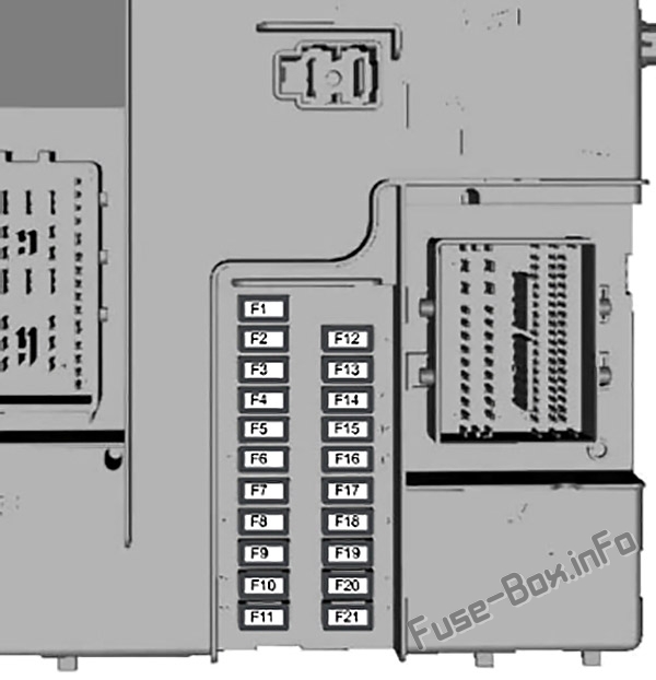
Assignment of the fuses in the Body Control Module
| № | Amp | Description |
|---|---|---|
| F1 | 15A | Central locking system 2. |
| F2 | 15A | Central locking system 1. |
| F3 | 15A | Ignition switch. Auxiliary battery relay. |
| F4 | 5A | Parking aid module. |
| F5 | 5A | Rain sensor module. Autolamp module. |
| F6 | 15A | Windshield washer pump. |
| F7 | 7.5A | Exterior mirrors. |
| F8 | 15A | Front fog lamps. |
| F9 | 10A | Right-hand high beam. |
| F10 | 10A | Left-hand high beam. |
| F11 | 25A | Right-hand exterior lamps. Left-hand side lamps. |
| F12 | 20A | Anti-theft alarm. Battery back-up sounder. |
| F13 | 15A | Data link connector. Auxiliary power point relay. Interior lighting. |
| F14 | 25A | Daytime running lamps. Direction indicators. Rear fog lamps. |
| F15 | 25A | Right-hand side lamps. Left-hand exterior lamps. Central high mounted brake lamp. |
| F16 | 20A | Audio control. |
| F17 | 7.5A | Heater control. Instrument cluster. Blower motor. |
| F18 | 10A | Headlamp switch. Steering wheel module. |
| F19 | 5A | Front control/display interface module. |
| F20 | 5A | Passive anti-theft system and ignition. Ignition. |
| F21 | 3A | Audio front control module and accessory relay. |
Engine Compartment Fuse Box
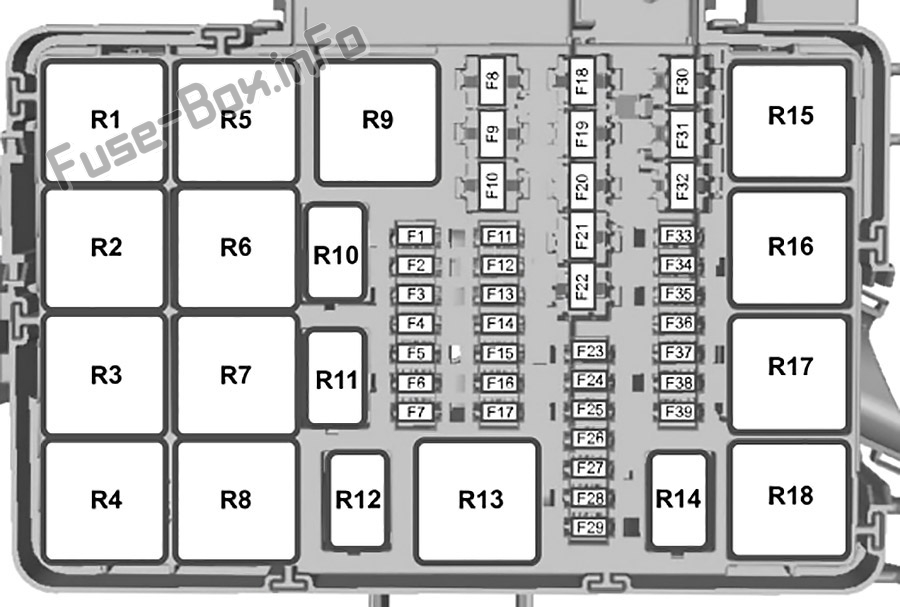
Assignment of the fuses in the engine compartment
| № | Amp | Description |
|---|---|---|
| F1 | – | Not used. |
| F2 | – | Not used. |
| F3 | – | Not used. |
| F4 | – | Not used. |
| F5 | 3A | Powertrain control module. |
| F6 | 3A | Anti-lock brake system module. |
| F7 | 7.5A | Powertrain control module. Glow plug module. |
| F8 | – | Not used. |
| F9 | 30A | Windshield wiper motor. |
| F10 | 30A | Auxiliary windshield wiper motor. |
| F11 | 10A | Air conditioning clutch. |
| F12 | 20A | Glow plugs. |
| F13 | – | Not used. |
| F14 | – | Not used. |
| F15 | – | Not used. |
| F16 | – | Not used. |
| F17 | – | Not used. |
| F18 | 40A | Anti-lock brake system module. |
| F19 | 30A | Starter relay. |
| F20 | 60A | Glow plug module. |
| F21 | 60A | Ignition relay. |
| F22 | – | Not used |
| F23 | 25A | Anti-lock brake system module. |
| F24 | 7.5A | Fuel pump relay. |
| F25 | – | Not used. |
| F26 | 3 A | Econetic coolant valve. |
| F27 | – | Not used. |
| F28 | – | Not used. |
| F29 | – | Audio front control module. |
| F30 | 60A | Low-speed and high-speed cooling fan. |
| F31 | – | Not used. |
| F32 | 60A | Windshield wiper motor relay. |
| F33 | – | Not used. |
| F34 | – | Not used. |
| F35 | 15A | Powertrain control module. |
| F36 | 7.5A | Mass air flow sensor. |
| F37 | 7.5A | Fuel metering valve. |
| F38 | 7.5A | Air conditioning clutch relay. |
| F39 | 15A | Low-speed and high-speed cooling fan. Glow plug relay. Fuel vaporizer system fuel pump. Heated oxygen sensor. Econetic coolant valve relay. |
| Relays | ||
| R1 | Ignition. | |
| R2 | Starter motor. | |
| R3 | Rear window wiper. | |
| R4 | Windshield wiper motor. | |
| R5 | Not used. | |
| R6 | Not used. | |
| R7 | Not used. | |
| R8 | Not used. | |
| R9 | Not used. | |
| R10 | Air conditioning clutch. | |
| R11 | Glow plugs. | |
| R12 | Fuel pump. | |
| R13 | Not used. | |
| R14 | Econetic coolant valve. | |
| R15 | Low-speed cooling fan. | |
| R16 | Not used. | |
| R17 | Powertrain control module. | |
| R18 | High-speed cooling fan. |


