


Fuse Layout Ford F150 2009-2014
Contents

Cigar lighter (power outlet) fuses in the Ford F-150 are the fuses №22 (Cigar lighter), №33 (110V AC power point, since 2011), №65 (Auxiliary power point (instrument panel)), №66 (Auxiliary power point (inside center console)) and №72 (Auxiliary power point (Rear)) in the Engine compartment fuse box.
Table of Contents
Fuse box location
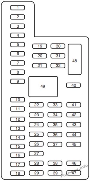
Passenger compartment
The fuse panel is located under the right-hand side of the instrument panel behind the cover.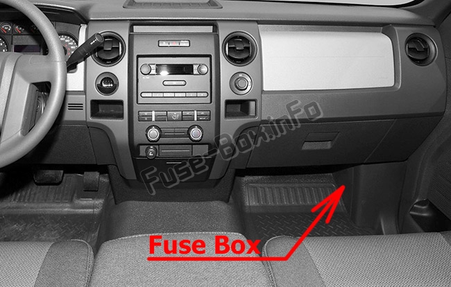
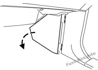
To remove the trim panel for access to the fuse box, pull the panel toward you and swing it out away from the side and remove it.
To reinstall it, line up the tabs with the grooves on the panel, then push it shut. To remove the fuse box cover, press in the tabs on both sides of the cover, then pull the cover off.
To reinstall the fuse box cover, place the top part of the cover on the fuse panel, then push the bottom part of the cover until you hear it click shut. Gently pull on the cover to make sure it is seated properly.
Engine compartment
The power distribution box is located in the engine compartment.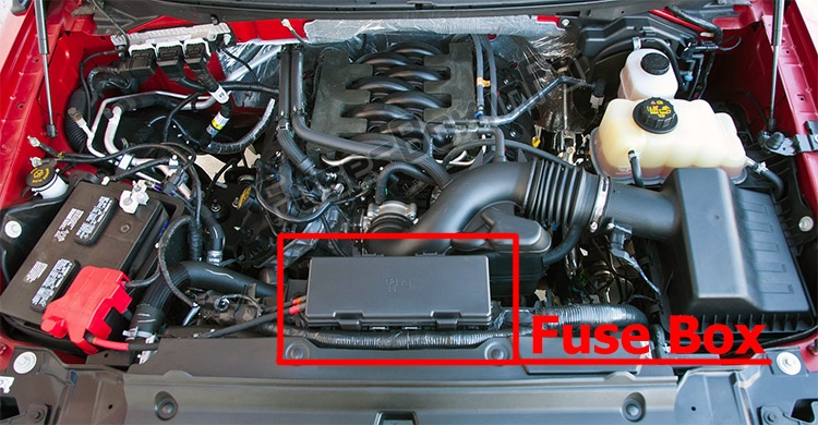
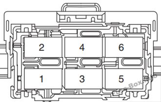
Auxiliary relay box (SVT Raptor only)
The relay box is located in the left rear corner of the engine compartment.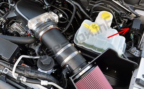
Fuse box diagrams
2009
Passenger compartment
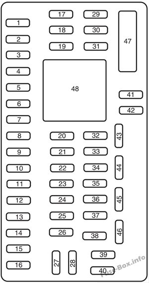
Assignment of the fuses in the Passenger compartment (2009)
| № | Amp rating | Protected Circuits |
|---|---|---|
| 1 | 30A | Moon roof |
| 2 | 15A | Not used (spare) |
| 3 | 15A | Not used (spare) |
| 4 | 30A | Not used (spare) |
| 5 | 10A | Keypad illumination, Brake Shift Interlock (BSI), SJB microprocessor power |
| 6 | 20A | Turn signals, Stop lamps |
| 7 | 10A | Low beam headlamps (left) |
| 8 | 10A | Low beam headlamps (right) |
| 9 | 15A | Interior courtesy lights, Cargo lamps |
| 10 | 15A | Backlighting, Puddle lamps |
| 11 | 10A | Not used (spare) |
| 12 | 7.5A | Power mirror switch, Memory seat module microprocessor power, Steering column switch |
| 13 | 5A | SYNC |
| 14 | 10A | Not used (spare) |
| 15 | 10A | Climate control |
| 16 | 15A | Ignition switch feed |
| 17 | 20A | All lock motor feeds |
| 18 | 20A | Driver memory seat switch |
| 19 | 25A | Not used (spare) |
| 20 | 15A | Adjustable pedals, Datalink |
| 21 | 15A | Fog lamps, Fog lamp indicator |
| 22 | 15A | Park lamps, Side marker lamps |
| 23 | 15A | High beam headlamps |
| 24 | 20A | Horn |
| 25 | 10A | Interior demand lamps, Mid box power feed |
| 26 | 10A | Instrument panel cluster, Key out inhibit solenoid, Radio info display (CID), Radio buttons, Key-in chime |
| 27 | 20A | Not used |
| 28 | 5A | Radio muting |
| 29 | 5A | Instrument panel cluster |
| 30 | 5A | Passenger airbag disable indicator |
| 31 | 10A | Restraints control module |
| 32 | 10A | Non-integrated compass module, Heated-only seat module |
| 33 | 10A | Trailer brake controller |
| 34 | 5A | Electronic locking differential indicator |
| 35 | 10A | Rear park assist |
| 36 | 5A | PATS transceiver |
| 37 | 10A | Not used (spare) |
| 38 | 20A | Subwoofer |
| 39 | 20A | Radio, Navigation display |
| 40 | 20A | Not used (spare) |
| 41 | 15A | EC mirror, Door lock switch illumination, Radio accessory delay |
| 42 | 10A | Not used (spare) |
| 43 | 10A | Heated mirror/backlight relay, Rain sensor, Reverse camera |
| 44 | 10A | Not used (spare) |
| 45 | 5A | Front wiper logic, Blower motor relay |
| 46 | 7.5A | Occupant classification sensor (OCS) |
| 47 | 30A Circuit Breaker | Power windows, Moon roof, Power sliding backlight |
| 48 | — | Delayed accessoiy relay (Feeds fuse 41 and circuit breaker 47) |
Engine compartment
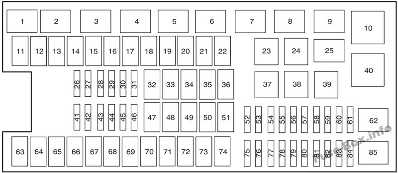
Assignment of the fuses in the Power distribution box (2009)
| № | Amp rating | Protected Circuits |
|---|---|---|
| 1 | — | PCM power relay |
| 2 | — | Starter relay |
| 3 | — | Blower motor relay |
| 4 | — | Heated backlite relay |
| 5 | — | Not used |
| 6 | — | Trailer tow park lamp relay |
| 7 | — | Not used |
| 8 | — | Fuel pump |
| 9 | — | Trailer tow battery charger |
| 10 | — | Not used |
| 11 | 30A** | Power running board motors |
| 12 | — | Not used |
| 13 | 30A ** | Starter relay |
| 14 | 30A** | Passenger power seats |
| 15 | — | Not used |
| 16 | — | Not used |
| 17 | 30A** | Trailer brake |
| 18 | — | Not used |
| 19 | — | Not used |
| 20 | 20A** | 4×4 module (ESOF) |
| 21 | 30A** | Trailer tow battery charge |
| 22 | 20A** | Cigar lighter |
| 23 | — | A/C clutch relay |
| 24 | — | Not used |
| 25 | — | Not used |
| 26 | 10 A* | PCM (KAPWR), Canister vent solenoid, Transmission, PCM relay |
| 27 | 20 A* | Fuel pump relay |
| 28 | — | Not used |
| 29 | 10 A* | 4×4 |
| 30 | 10 A* | A/C clutch |
| 31 | 20 A* | Trailer tow park lamp relay |
| 32 | 40A** | Heated backlite/mirror relay |
| 33 | — | Not used |
| 34 | 40A** | PCM relay |
| 35 | — | Not used |
| 36 | 30A** | Roll stability control module (RSC) |
| 37 | — | Trailer tow left hand stop/turn relay |
| 38 | — | Trailer tow right hand stop/turn relay |
| 39 | — | Back up lamps |
| 40 | — | Not used |
| 41 | — | Not used |
| 42 | — | Not used |
| 43 | 20 A* | Backup lamp relay |
| 44 | — | Not used |
| 45 | 20 A* | Trailer tow stop turn relay feed |
| 46 | 15 A* | Brake on/off (BOO) switch |
| 47 | 60A** | Roll stability control module (RSC) |
| 48 | — | Not used |
| 49 | 30A** | Wiper motor, washer pump |
| 50 | — | Not used |
| 51 | 40A** | Blower motor relay |
| 52 | — | Not used |
| 53 | 5A* | Power train control module (PCM), 6R80 transmission |
| 54 | 5A* | 4×4 module, Back up lamp, Roll Stability Control (RSC), Trailer tow battery charge relay |
| 55 | 5A* | Electronic compass mirror (6R transmission only) |
| 56 | — | Not used |
| 57 | — | Not used |
| 58 | 15 A* | Trailer tow backup lamps |
| 59 | 15 A* | Heated mirrors |
| 60 | — | One-touch Start diode |
| 61 | — | Fuel pump diode |
| 62 | — | Not used |
| 63 | — | Not used |
| 64 | 30A** | Amplifier |
| 65 | 20A** | Auxiliary power point (instrument panel) |
| 66 | 20A** | Auxiliary power point (inside center console) |
| 67 | — | Not used |
| 68 | 20A** | 4×4 module |
| 69 | 30A** | Passenger heated/cooled seats |
| 70 | — | Not used |
| 71 | — | Not used |
| 72 | 20A** | Auxiliary power point (Rear) |
| 73 | — | Not used |
| 74 | 30A** | Driver power seat |
| 75 | 15 A* | PCM – VPWR1 |
| 76 | 20 A* | VPWR2,VBV, MAF/IAT, CMS 12 and 22 with 6R80 transmission, Brake on/off switch (BOO) |
| 77 | 10 A* | VPWR3, Electric fan clutch, A/C clutch relay coil, Floor shifter (4-speed transmission) |
| 78 | 25A* | Ignition coils, VPWR4 |
| 79 | 10 A* | CMS 4-speed transmission, 12 and 22 with 4-speed transmission |
| 80 | 5A* | Steering wheel illumination |
| 81 | — | Not used |
| 82 | 10 A* | Traction brake control module (TBCM), Center high mount brake lamp (CHMSL), After market CHMSL |
| 83 | — | Not used |
| 84 | diode | A/C clutch |
| 85 | — | Not used |
| * Mini Fuses ** Cartridge Fuses |
2010
Passenger compartment
Assignment of the fuses in the Passenger compartment (2010)
| № | Amp Rating | Protected Circuits |
|---|---|---|
| 1 | 30A | Moon roof |
| 2 | 15A | Not used (spare) |
| 3 | 15A | Not used (spare) |
| 4 | 30A | Not used (spare) |
| 5 | 10A | Keypad illumination, Brake Shift Interlock (BSI), SJB microprocessor power |
| 6 | 20A | Turn signals, Stop lamps |
| 7 | 10A | Low beam headlamps (left) |
| 8 | 10A | Low beam headlamps (right) |
| 9 | 15A | Interior courtesy lights, Cargo lamps |
| 10 | 15A | Backlighting, Puddle lamps |
| 11 | 10A | GPS module |
| 12 | 7.5A | Power mirror switch, Memory seat module microprocessor power, Steering column switch |
| 13 | 5A | SYNC® |
| 14 | 10A | Ambient lighting module |
| 15 | 10A | Climate control |
| 16 | 15A | Ignition switch feed |
| 17 | 20A | All lock motor feeds |
| 18 | 20A | Driver memory seat switch |
| 19 | 25A | Not used (spare) |
| 20 | 15A | Adjustable pedals, Datalink |
| 21 | 15A | Fog lamps, Fog lamp indicator |
| 22 | 15A | Park lamps, Side marker lamps |
| 23 | 15A | High beam headlamps |
| 24 | 20A | Horn |
| 25 | 10A | Interior demand lamps, Mid box power feed |
| 26 | 10A | Instrument panel cluster, Key out inhibit solenoid, Radio info display (CID), Radio buttons, Key-in chime |
| 27 | 20A | Not used |
| 28 | 5A | Radio muting |
| 29 | 5A | Instrument panel cluster |
| 30 | 5A | Passenger airbag disable indicator |
| 31 | 10A | Restraints control module |
| 32 | 10A | Non-integrated compass module, Heated-only seat module |
| 33 | 10A | Trailer brake controller |
| 34 | 5A | Electronic locking differential indicator |
| 35 | 10A | Rear park assist |
| 36 | 5A | Passive anti-theft system transceiver |
| 37 | 10A | Upfitter relay coils |
| 38 | 20A | Subwoofer |
| 39 | 20A | Radio, Navigation display |
| 40 | 20A | Rear heated seats module |
| 41 | 15A | Auto dimming rear view mirror, Door lock switch illumination, Radio accessoiy delay |
| 42 | 10A | Not used (spare) |
| 43 | 10A | Heated mirror/backlight relay, Rain sensor, Reverse camera |
| 44 | 10A | Not used (spare) |
| 45 | 5A | Front wiper logic, Blower motor relay |
| 46 | 7.5A | Occupant classification sensor (OCS) |
| 47 | 30A Circuit Breaker | Power windows, Moon roof, Power sliding backlight |
| 48 | 15A | Delayed accessory relay (Feeds fuse 41 and circuit breaker 47) |
Engine compartment
Assignment of the fuses in the Power distribution box (2010)
| № | Amp Rating | Protected Circuits |
|---|---|---|
| 1 | — | Powertrain control module (PCM) power relay |
| 2 | — | Starter relay |
| 3 | — | Blower motor relay |
| 4 | — | Heated backlite relay |
| 5 | — | Electric fan relay (high speed) |
| 6 | — | Trailer tow park lamp relay |
| 7 | — | Upfitter 1 relay |
| 8 | — | Fuel pump |
| 9 | — | Trailer tow battery charger |
| 10 | — | Upfitter 2 relay |
| 11 | 30A** | Power running board motors |
| 12 | 40A** | Electric fan |
| 13 | 30A** | Starter relay |
| 14 | 30A** | Passenger power seats |
| 15 | 40A** | Electric fan |
| 16 | — | Not used |
| 17 | 30A** | Trailer brake |
| 18 | 30A** | Upfitter 1 |
| 19 | 30A** | Upfitter 2 |
| 20 | 20A** | 4×4 module (ESOF) |
| 21 | 30A** | Trailer tow battery charge |
| 22 | 20A** | Cigar lighter |
| 23 | — | A/C clutch relay |
| 24 | — | Upfitter 4 relay |
| 25 | — | Heated mirror relay |
| 26 | 10 A* | PCM – keep alive power, Canister vent solenoid, Transmission, PCM relay |
| 27 | 20 A* | Fuel pump relay |
| 28 | 10 A* | Upfitter 4 |
| 29 | 10 A* | 4×4 |
| 30 | 10 A* | A/C clutch |
| 31 | 20 A* | Trailer tow park lamp relay |
| 32 | 40A** | Heated backlite |
| 33 | — | Not used |
| 34 | 40A** | PCM relay |
| 35 | — | Not used |
| 36 | 30A** | Roll stability control module (RSC) |
| 37 | — | Trailer tow left hand stop/turn relay |
| 38 | — | Trailer tow right hand stop/turn relay |
| 39 | — | Back up lamps relay |
| 40 | — | Electric fan relay |
| 41 | 15 A* | Heated mirror |
| 42 | — | Not used |
| 43 | 20 A* | Backup lamp relay |
| 44 | 15 A* | Upfitter 3 |
| 45 | 20 A* | Trailer tow stop turn relay feed |
| 46 | 15 A* | Brake on/off (BOO) switch |
| 47 | 60A** | RSC module |
| 48 | — | Not used |
| 49 | 30A** | Wiper motor, washer pump |
| 50 | — | Not used |
| 51 | 40A** | Blower motor relay |
| 52 | — | Not used |
| 53 | 5A* | PCM, 6R80 transmission |
| 54 | 5A* | 4×4 module, Back up lamp, RSC, Trailer tow battery charge relay |
| 55 | 5A* | Electronic compass mirror (6R transmission only) |
| 56 | — | Not used |
| 57 | — | Not used |
| 58 | 15 A* | Trailer tow backup lamps |
| 59 | — | Not used |
| 60 | — | One-touch Start diode |
| 61 | — | Fuel pump diode |
| 62 | — | Upfitter 3 relay |
| 63 | 25A** | Electric fan |
| 64 | 30A** | Amplifier |
| 65 | 20A** | Auxiliary power point (instrument panel) |
| 66 | 20A** | Auxiliary power point (inside center console) |
| 67 | — | Not used |
| 68 | 20A** | 4×4 module |
| 69 | 30A** | Passenger heated/cooled seats |
| 70 | — | Not used |
| 71 | — | Not used |
| 72 | 20A** | Auxiliary power point (Rear) |
| 73 | — | Not used |
| 74 | 30A** | Driver power seat |
| 75 | 15 A* | PCM – voltage power 1 |
| 76 | 20 A* | Voltage power 2, Voltage – battery voltage, Mass air flow/Intake air temp, CMS 12 and 22 with 6R80 transmission, Brake on/off switch (BOO) |
| 77 | 10 A* | Voltage power 3, Electric fan clutch, A/C clutch relay coil, Floor shifter (4-speed transmission) |
| 78 | 15 A* | Ignition coils, Voltage power 4 |
| 79 | 10 A* | CMS 4-speed transmission, 12 and 22 with 4-speed transmission |
| 80 | 5A* | Steering wheel illumination |
| 81 | — | Not used |
| 82 | 10 A* | Trailer brake control module (TBCM), After market center high mounted stop lamp (CHMSL) |
| 83 | — | Not used |
| 84 | — | Not used |
| 85 | — | Electric fan relay (low speed) |
| * Mini Fuses ** Cartridge Fuses |
2011
Passenger compartment
Assignment of the fuses in the Passenger compartment (2011)
| № | Amp Rating | Protected Circuits |
|---|---|---|
| 1 | 30A | Driver side front window |
| 2 | 15A | SYNC® |
| 3 | 30A | Passenger side front window |
| 4 | 10A | Interior lamps |
| 5 | 20A | Memory module |
| 6 | 5A | Not used (spare) |
| 7 | 7.5A | Power mirror switch, Memory seat module |
| 8 | 10A | Not used (spare) |
| 9 | 10A | Radio display, GPS module, Navigation display |
| 10 | 10A | Run/accessory relay |
| 11 | 10A | Instrument cluster |
| 12 | 15A | Interior lighting, Puddle lamps, Backlighting, Cargo lamp |
| 13 | 15A | Right turn signals/stop lamps |
| 14 | 15A | Left turn signals/stop lamps |
| 15 | 15A | Reverse lights, High-mounted stop lamp |
| 16 | 10A | Right low-beam headlamp |
| 17 | 10A | Left low-beam headlamp |
| 18 | 10A | Brake-shift interlock, Keypad illumination, PCM wakeup, PATS |
| 19 | 20A | Audio amplifier |
| 20 | 20A | Power door locks |
| 21 | 10A | Ambient lighting |
| 22 | 20A | Horn |
| 23 | 15A | Steering wheel control module |
| 24 | 15A | Datalink connector, Steering wheel control module |
| 25 | 15A | Not used (spare) |
| 26 | 5A | Radio frequency module |
| 27 | 20A | Not used (spare) |
| 28 | 15A | Ignition switch |
| 29 | 20A | Radio/Navigation |
| 30 | 15A | Front parking lamps |
| 31 | 5A | BOO – IP, BOO – Engine |
| 32 | 15A | Delay/accessory – moon roof, power windows, locks, Automatic dimming mirror/Compass |
| 33 | 10A | Heated seats |
| 34 | 10A | Reverse sensing system, 4×4 switch, Rear video, Off road indicator (SVT Raptor) |
| 35 | 5A | Hill descent switch (SVT Raptor) |
| 36 | 10A | Restraint control module, Occupant classification system module |
| 37 | 10A | Trailer brake control |
| 38 | 10A | Delayed accessory – 110V power point, Radio (AM/FiM) |
| 39 | 15A | High beam headlamps |
| 40 | 10A | Rear park lamps |
| 41 | 7.5A | Passenger airbag deactivation indicator, Upfitter switch (SVT Raptor) |
| 42 | 5A | Overdrive cancel switch |
| 43 | 10A | Not used (spare) |
| 44 | 10A | Not used (spare) |
| 45 | 5A | Not used (spare) |
| 46 | 10A | Climate controls module |
| 47 | 15A | Fog lamps, Exterior mirror turn signals |
| 48 | 30A Circuit Breaker | Power rear windows, Power sliding back window |
| 49 | Relay | Delayed accessory |
Engine compartment
Assignment of the fuses in the Power distribution box (2011)
| № | Amp Rating | Protected Circuits |
|---|---|---|
| 1 | — | Powertrain control module (PCM) relay (3.7L, 5.0L and 6.2L engines) |
| 2 | — | Starter relay |
| 3 | — | Blower motor relay |
| 4 | — | Rear window defroster relay |
| 5 | — | Electric fan relay (high speed) |
| 6 | — | Trailer tow (TT) park lamp relay |
| 7 | — | Run/start relay |
| 8 | — | Fuel pump relay |
| 9 | — | TT Battery charger relay |
| 10 | — | PCM relay (3.5L engine) |
| 11 | 30A** | Power running board motors |
| 12 | 40A** | Electric fan |
| 12 | 50A** | Electric fan (6.2L with max trailer tow, SVT Raptor) |
| 13 | 30A** | Starter relay power |
| 14 | 30A** | Passenger power seat |
| 15 | 40A** | Electric fan |
| 15 | 50A** | Electric fan (6.2L with max trailer tow, SVT Raptor) |
| 16 | — | Not used |
| 17 | 30A** | Trailer brake control |
| 18 | 30A** | Upfitter 1 (SVT Raptor) |
| 19 | 30A** | Upfitter 2 (SVT Raptor) |
| 20 | 20A** | 4×4 module (electronic shift) |
| 21 | 30A** | TT battery charge relay power |
| 22 | 20A** | Cigar lighter |
| 23 | — | A/C clutch relay |
| 24 | — | Not used |
| 25 | — | Vacuum pump relay (3.5L engine) |
| 26 | 10 A* | PCM – keep alive power, PCM relay coil, canister vent solenoid (3.7L, 5.0L and 6.2L engines) |
| 27 | 20 A* | Fuel pump relay power |
| 28 | 10 A* | Upfitter 4 (SVT Raptor) |
| 29 | 10 A* | 4×4 IWE solenoid |
| 30 | 10 A* | A/C clutch |
| 31 | 15 A* | Run/start relay power |
| 32 | 40A** | Rear window defroster relay power |
| 33 | 40A** | 110V AC power point |
| 34 | 40A** | PCM relay power (3.7L, 5.0L and 6.2L engines) |
| 34 | 50A** | PCM relay power (3.5L engine) |
| 35 | — | Not used |
| 36 | 30A** | Roll stability control (RSC)/Anti-lock brake system (ABS) |
| 37 | — | TT left stop/turn relay |
| 38 | — | TT right stop/turn relay |
| 39 | — | TT back-up lamps relay |
| 40 | — | Electric fan relay |
| 41 | — | Not used |
| 42 | 5A* | Run/start coil |
| 43 | 15 A* | TT back-up lamp relay power |
| 44 | 15 A* | Upfitter 3 (SVT Raptor) |
| 45 | 10 A* | Alternator sensor (non-6.2L engines) |
| 46 | 10 A* | Brake on/off (BOO) switch |
| 47 | 60A** | RSC/ABS module |
| 48 | 20A** | Moon roof |
| 49 | 30A** | Wipers |
| 50 | — | Not used |
| 51 | 40A** | Blower motor relay power |
| 52 | 5A* | Run/start – Electronic power assist steering, Blower relay coil |
| 53 | 5A* | Run/start – PCM |
| 54 | 5A* | Run/start – 4×4 module, Back-up lamps, RSC/ABS, TT battery charge relay coil, Rear window defroster relay coil |
| 55 | — | Not used |
| 56 | 15 A* | Heated mirrors |
| 57 | — | Not used |
| 58 | — | Not used |
| 59 | — | Not used |
| 60 | — | Not used |
| 61 | — | Not used |
| 62 | — | Wiper motor relay |
| 63 | 25A** | Electric fan |
| 64 | 40A** | Vacuum pump relay power (3.5L engine) |
| 65 | 20A** | Auxiliary power point (instrument panel) |
| 66 | 20A** | Auxiliary power point (inside center console) |
| 67 | 20A** | TT park lamps relay power |
| 68 | 25A** | 4×4 module |
| 69 | 30A** | Passenger heated/cooled seats |
| 70 | — | Not used |
| 71 | 20A** | Heated rear seats |
| 72 | 20A** | Auxiliary power point (Rear) |
| 73 | 20A** | TT stop/turn lamps relay power |
| 74 | 30A** | Driver power seat/memory module |
| 75 | 15 A* | PCM – voltage power 1 (3.7L, 5.0L, 6.2L engines PCM module) |
| 75 | 25A* | PCM – voltage power 1 (3.5L engine PCM module) |
| 76 | 20 A* | PCM – Voltage power 2 (General powertrain components, Mass air flow/Intake air temp sensor) (3.7L, 5.0L, 6.2L engines) |
| 76 | 20 A* | PCM – Voltage power 2 (General powertrain components, Canister vent solenoid) (3.5L engine) |
| 77 | 10 A* | PCM – Voltage power 3 (Emission related powertrain components, Electric fan relays coil) |
| 78 | 15 A* | PCM – Voltage power 4 – Ignition coils (3.5L, 3.7L, 5.0L engines) |
| 78 | 20 A* | PCM – Voltage power 4 – Ignition coils (6.2L engine) |
| 79 | 5A* | Rain sensor |
| 80 | — | Not used |
| 81 | — | Not used |
| 82 | — | Not used |
| 83 | — | Not used |
| 84 | — | Not used |
| 85 | — | Electric fan relay (low speed) |
| * Mini fuse ** Cartridge fuse |
Auxiliary relay box
| № | Amp Rating | Description |
|---|---|---|
| 1 | — | Upfitter 1 relay |
| 2 | — | Upfitter 2 relay |
| 3 | — | Upfitter 3 relay |
| 4 | — | Upfitter 4 relay |
| 5 | — | Not used |
| 6 | — | Not used |
2012
Passenger compartment
Assignment of the fuses in the Passenger compartment (2012)
| № | Amp Rating | Protected Circuits |
|---|---|---|
| 1 | 30A | Driver side front window |
| 2 | 15A | SYNC® |
| 3 | 30A | Passenger side front window |
| 4 | 10A | Interior lamps |
| 5 | 20A | Memory module |
| 6 | 5A | Not used (spare) |
| 7 | 7.5A | Power mirror switch, Memory seat module |
| 8 | 10A | Not used (spare) |
| 9 | 10A | Radio display, GPS module, Navigation display |
| 10 | 10A | Run/accessory relay |
| 11 | 10A | Instrument cluster |
| 12 | 15A | Interior lighting, Puddle lamps, Backlighting, Cargo lamp |
| 13 | 15A | Right turn signals/stop lamps |
| 14 | 15A | Left turn signals/stop lamps |
| 15 | 15A | Reverse lights, High-mounted stop lamp |
| 16 | 10A | Right low-beam headlamp |
| 17 | 10A | Left low-beam headlamp |
| 18 | 10A | Brake-shift interlock, Keypad illumination, PCM wakeup, PATS |
| 19 | 20A | Audio amplifier |
| 20 | 20A | Power door locks |
| 21 | 10A | Ambient lighting |
| 22 | 20A | Horn |
| 23 | 15A | Steering wheel control module |
| 24 | 15A | Datalink connector, Steering wheel control module |
| 25 | 15A | Not used (spare) |
| 26 | 5A | Radio frequency module |
| 27 | 20A | Not used (spare) |
| 28 | 15A | Ignition switch |
| 29 | 20A | Radio/Navigation |
| 30 | 15A | Front parking lamps |
| 31 | 5A | BOO – IP, BOO – Engine |
| 32 | 15A | Delay/accessory – moon roof, power windows, locks, Automatic dimming mirror/Compass |
| 33 | 10A | Heated seats |
| 34 | 10A | Reverse sensing system, 4×4 switch, Rear video, Off road indicator (SVT Raptor) |
| 35 | 5A | Hill descent switch (SVT Raptor) |
| 36 | 10A | Restraint control module, Occupant classification system module |
| 37 | 10A | Trailer brake control |
| 38 | 10A | Delayed accessory – 110V power point, Radio (AM/FM) |
| 39 | 15A | High beam headlamps |
| 40 | 10A | Rear park lamps |
| 41 | 7.5A | Passenger airbag deactivation indicator, Upfitter switch (SVT Raptor) |
| 42 | 5A | Overdrive cancel switch |
| 43 | 10A | Not used (spare) |
| 44 | 10A | Not used (spare) |
| 45 | 5A | Not used (spare) |
| 46 | 10A | Climate controls module |
| 47 | 15A | Fog lamps, Exterior mirror turn signals |
| 48 | 30A Circuit Breaker | Power rear windows, Power sliding back window |
| 49 | Relay | Delayed accessory |
Engine compartment
Assignment of the fuses in the Power distribution box (2012)
| № | Amp Rating | Protected Circuits |
|---|---|---|
| 1 | Powertrain control module (PCM) relay (3.7L, 5.0L and 6.2L engines) | |
| 2 | — | Starter relay |
| 3 | — | Blower motor relay |
| 4 | — | Rear window defroster relay |
| 5 | — | Electric fan relay (high speed) |
| 6 | — | Trailer tow (TT) park lamp relay |
| 7 | — | Run/start relay |
| 8 | — | Fuel pump relay |
| 9 | — | TT Battery charger relay |
| 10 | — | PCM relay (3.5L engine) |
| 11 | 30A** | Power running board motors |
| 12 | 40A** | Electric fan |
| 12 | 50A** | Electric fan (6.2L with max trailer tow, SVT Raptor) |
| 13 | 30A** | Starter relay power |
| 14 | 30A** | Passenger power seat |
| 15 | 40A** | Electric fan |
| 15 | 50A** | Electric fan (6.2L with max trailer tow, SVT Raptor) |
| 16 | — | Not used |
| 17 | 30A** | Trailer brake control |
| 18 | 30A** | Upfitter 1 (SVT Raptor) |
| 19 | 30A** | Upfitter 2 (SVT Raptor) |
| 20 | 20A** | 4×4 module (electronic shift) |
| 21 | 30A** | TT battery charge relay power |
| 22 | 20A** | Cigar lighter |
| 23 | — | A/C clutch relay |
| 24 | — | Not used |
| 25 | — | Vacuum pump relay (3.5L engine) |
| 26 | 10 A* | PCM – keep alive power, PCM relay coil, canister vent solenoid (3.7L, 5.0L and 6.2L engines) |
| 27 | 20 A* | Fuel pump relay power |
| 28 | 10 A* | Upfitter 4 (SVT Raptor) |
| 29 | 10 A* | 4×4 IWE solenoid |
| 30 | 10 A* | A/C clutch |
| 31 | 15 A* | Run/start relay power |
| 32 | 40A** | Rear window defroster relay power, Heated mirror relay power |
| 33 | 40A** | 110V AC power point |
| 34 | 40A** | PCM relay power (3.7L, 5.0L and 6.2L engines) |
| 34 | 50A** | PCM relay power (3.5L engine) |
| 35 | — | Not used |
| 36 | 30A** | Roll stability control (RSC)/Anti-lock brake system CABS) |
| 37 | — | TT left stop/turn relay |
| 38 | — | TT right stop/turn relay |
| 39 | — | TT back-up lamps relay |
| 40 | — | Electric fan relay |
| 41 | 15 A* | Front camera washer (SVT Raptor) |
| 42 | 5A* | Run/start coil |
| 43 | 15 A* | TT back-up lamp relay power |
| 44 | 15 A* | Upfitter 3 (SVT Raptor) |
| 45 | 10 A* | Alternator sensor (non-6.2L engines) |
| 46 | 10 A* | Brake on/off (BOO) switch |
| 47 | 60A** | RSC/ABS module |
| 48 | 20A** | Moon roof |
| 49 | 30A** | Wipers |
| 50 | — | Not used |
| 51 | 40A** | Blower motor relay power |
| 52 | 5A* | Run/start – Electronic power assist steering, Blower relay coil |
| 53 | 5A* | Run/start – PCM |
| 54 | 5A* | Run/start – 4×4 module, Back-up lamps, RSC/ABS, TT battery charge relay coil, Rear window defroster relay coil, Front camera washer relay coil (SVT Raptor) |
| 55 | — | Not used |
| 56 | 15 A* | Heated mirrors |
| 57 | — | Not used |
| 58 | — | Not used |
| 59 | — | Not used |
| 60 | — | Not used |
| 61 | — | Not used |
| 62 | — | Wiper motor relay |
| 63 | 25A** | Electric fan |
| 64 | 40A** | Vacuum pump relay power (3.5L engine) |
| 65 | 20A** | Auxiliary power point (instrument panel) |
| 66 | 20A** | Auxiliary power point (inside center console) |
| 67 | 20A** | TT park lamps relay power |
| 68 | 25A** | 4×4 module |
| 69 | 30A** | Passenger heated/cooled seats |
| 70 | — | Not used |
| 71 | 20A** | Heated rear seats |
| 72 | 20A** | Auxiliary power point (Rear) |
| 73 | 20A** | TT stop/turn lamps relay power |
| 74 | 30A** | Driver power seat/memory module |
| 75 | 15 A* | PCM – voltage power 1 (3.7L, 5.0L, 6.2L engines PCM module) |
| 75 | 25A* | PCM – voltage power 1 (3.5L engine PCM module) |
| 76 | 20 A* | PCM – Voltage power 2 (General powertrain components, Mass air flow/Intake air temp sensor) (3.7L, 5.0L, 6.2L engines) |
| 76 | 20 A* | PCM – Voltage power 2 (General powertrain components, Canister vent solenoid) (3.5L engine) |
| 77 | 10 A* | PCM – Voltage power 3 (Emission related powertrain components, Electric fan relays coil) |
| 78 | 15 A* | PCM – Voltage power 4 – Ignition coils (3.5L, 3.7L, 5.0L engines) |
| 20 A* | PCM – Voltage power 4 – Ignition coils (6.2L engine) | |
| 79 | 5A* | Rain sensor |
| 80 | — | Not used |
| 81 | — | Not used |
| 82 | — | Not used |
| 83 | — | Not used |
| 84 | — | Not used |
| 85 | — | Electric fan relay (low speed) |
| * Mini fuse ** Cartridge fuse |
Auxiliary relay box
| № | Amp Rating | Description |
|---|---|---|
| 1 | — | Upfitter 1 relay |
| 2 | — | Upfitter 2 relay |
| 3 | — | Upfitter 3 relay |
| 4 | — | Upfitter 4 relay |
| 5 | — | Front camera washer relay |
| 6 | — | Not used |
2013
Passenger compartment
Assignment of the fuses in the Passenger compartment (2013)
| № | Amp Rating | Protected Components |
|---|---|---|
| 1 | 30A | Driver side front window |
| 2 | 15A | SYNC , Display module (8 inch) |
| 3 | 30A | Passenger side front window |
| 4 | 10A | Interior lamps |
| 5 | 20A | Memory module |
| 6 | 5A | Not used (spare) |
| 7 | 7.5A | Power mirror switch, Memory seat module |
| 8 | 10A | Not used (spare) |
| 9 | 10A | Radio display, GPS module, Electric finish panel module |
| 10 | 10A | Run/accessory relay |
| 11 | 10A | Instrument cluster |
| 12 | 15A | Interior lighting, Puddle lamps, Backlighting, Cargo lamp |
| 13 | 15A | Right turn signals/stop lamps |
| 14 | 15A | Left turn signals/stop lamps |
| 15 | 15A | Reverse lights, High-mounted stop lamp |
| 16 | 10A | Right low-beam headlamp |
| 17 | 10A | Left low-beam headlamp |
| 18 | 10A | Brake-shift interlock, Keypad illumination, Powertrain control module wakeup, Passive anti-theft system |
| 19 | 20A | Audio amplifier |
| 20 | 20A | Power door locks |
| 21 | 10A | Not used (spare) |
| 22 | 20A | Horn |
| 23 | 15A | Steering wheel control module |
| 24 | 15A | Datalink connector, Steering wheel control module |
| 25 | 15A | Not used (spare) |
| 26 | 5A | Radio frequency module |
| 27 | 20A | Not used (spare) |
| 28 | 15A | Ignition switch |
| 29 | 20A | Radio |
| 30 | 15A | Front parking lamps |
| 31 | 5A | Brake on/off – Instrument panel, Engine |
| 32 | 15A | Delay/accessory – moonroof, power windows, locks, Automatic dimming mirror/Compass, Trailer tow power telescope mirrors |
| 33 | 10A | Rear heated seats |
| 34 | 10A | Reverse sensing system, 4×4 switch, Rear video, Off road indicator (SVT Raptor), Front video (SVT Raptor), Camera splice module (SVT Raptor) |
| 35 | 5A | Hill descent switch (SVT Raptor) |
| 36 | 10A | Restraint control module, Occupant classification system module |
| 37 | 10A | Trailer brake control |
| 38 | 10A | Delayed accessory – 110 volt power point, Radio |
| 39 | 15A | High beam headlamps |
| 40 | 10A | Rear park lamps |
| 41 | 7.5A | Passenger airbag deactivation indicator, Upfitter switch (SVT Raptor) |
| 42 | 5A | Overdrive cancel switch |
| 43 | 10A | Not used (spare) |
| 44 | 10A | Not used (spare) |
| 45 | 5A | Not used (spare) |
| 46 | 10A | Climate controls module |
| 47 | 15A | Fog lamps, Exterior mirror turn signals |
| 48 | 30A Circuit Breaker | Power windows, Power sliding back window |
| 49 | Relay | Delayed accessory |
Engine compartment
Assignment of the fuses in the Power distribution box (2013)
| № | Amp Rating | Protected Components |
|---|---|---|
| 1 | — | Powertrain control module relay (3.7L, 5.0L and 6.2L engines) |
| 2 | — | Starter relay |
| 3 | — | Blower motor relay |
| 4 | — | Rear window defroster relay |
| 5 | — | Electric fan relay (high speed) |
| 6 | — | Trailer tow park lamp relay |
| 7 | — | Run/start relay |
| 8 | — | Fuel pump relay |
| 9 | — | Trailer tow battery charger relay |
| 10 | — | Powertrain control module relay (3.5L engine) |
| 11 | 30A** | Power running board motors |
| 12 | 40A** | Electric fan (3.7L, 5.0L) |
| 12 | 50A** | Electric fan (3.5L, 6.2L with max trailer tow’, SVT Raptor) |
| 13 | 30A** | Starter relay power |
| 14 | 30A** | Passenger power seat |
| 15 | 40A** | Electric fan (3.7L, 5.0L) |
| 15 | 50A** | Electric fan (3.5L, 6.2L with max trailer tow’, SVT Raptor) |
| 16 | 20A** | High intensity discharge headlamp – passenger side |
| 17 | 30A** | Trailer brake control |
| 18 | 30A** | Upfitter 1 (SVT Raptor) |
| 19 | 30A** | Upfitter 2 (SVT Raptor) |
| 20 | 20A** | 4×4 module (electronic shift) |
| 21 | 30A** | Trailer tow battery charge relay power |
| 22 | 20A** | Auxiliary power point (instrument panel) |
| 23 | — | A/C clutch relay |
| 24 | — | Not used |
| 25 | — | Not used |
| 26 | 10 A* | Powertrain control module – keep alive power and relay coil, canister vent solenoid (3.7L, 5.0L and 6.2L engines) |
| 27 | 20 A* | Fuel pump relay power |
| 28 | 10 A* | Upfitter 4 (SVT Raptor) |
| 29 | 10 A* | 4×4 integrated wheel end solenoid |
| 30 | 10 A* | A/C clutch relay power |
| 31 | 15 A* | Run/start relay power |
| 32 | 40A** | Rear window defroster relay power, Heated mirror relay power |
| 33 | 40A** | 110 volt AC power point |
| 34 | 40A** | Powertrain control module relay power (3.7L, 5.0L and 6.2L engines) |
| 34 | 50A** | Powertrain control module relay power (3.5L engine) |
| 35 | 20A** | High intensity discharge headlamps – driver side |
| 36 | 30A** | Roll stability control / Anti-lock brake system |
| 37 | — | Trailer tow left stop/turn relay |
| 38 | — | Trailer tow right stop/turn relay |
| 39 | — | Trailer tow back-up lamps relay |
| 40 | — | Electric fan relay |
| 41 | 15 A* | Front camera washer (SVT Raptor) |
| 42 | 5A* | Run/start relay coil |
| 43 | 15 A* | Trailer tow back-up lamp relay power |
| 44 | 15 A* | Upfitter 3 (SVT Raptor), Trailer tow power folding mirrors |
| 45 | 10 A* | Alternator sensor (3.5L, 3.7L and 5.0L engines) |
| 46 | 10 A* | Brake on/off switch |
| 47 | 60A** | Roll stability control / Anti-lock brake system module |
| 48 | 20A** | Moonroof |
| 49 | 30A** | Wiper relay power |
| 50 | — | Not used |
| 51 | 40A** | Blower motor relay power |
| 52 | 5A* | Run/start – Electronic power assist steering, Blower relay coil |
| 53 | 5A* | Run/start – Powertrain control module |
| 54 | 5A* | Run/start – 4×4 module, Back-up lamps, Roll stability control /Anti-lock brake system, Trailer tow batteiy charge relay coil, Rear window defroster relay coil, Front camera washer relay coil (SVT Raptor) |
| 55 | — | Not used |
| 56 | 15 A* | Heated mirrors |
| 57 | — | Not used |
| 58 | — | Not used |
| 59 | — | Not used |
| 60 | — | Not used |
| 61 | — | Not used |
| 62 | — | Wiper motor relay |
| 63 | 25A** | Electric fan relay power |
| 64 | — | Not used |
| 65 | 20A** | Auxiliary power point (instrument panel) |
| 66 | 20A** | Auxiliary power point (inside center console) |
| 67 | 20A** | Trailer tow park lamps relay power |
| 68 | 25A** | 4×4 module, 4×2 elocker module |
| 69 | 30A** | Front heated or heated/cooled seats |
| 70 | — | Not used |
| 71 | 20A** | Heated rear seats |
| 72 | 20A** | Auxiliary power point (rear) |
| 73 | 20A** | Trailer tow stop/turn lamps relay power |
| 74 | 30A** | Driver power seat/memory module |
| 75 | 15 A* | Powertrain control module -voltage power 1 (3.7L, 5.0L, 6.2L engines) |
| 75 | 25A* | Powertrain control module -voltage power 1 (3.5L engine) |
| 76 | 20 A* | Powertrain control module -Voltage power 2 (General powertrain components, Mass air flow/Intake air temp sensor) (3.7L, 5.0L, 6.2L engines) |
| 76 | 20 A* | Powertrain control module -Voltage power 2 (General powertrain components, Canister vent solenoid) (3.5L engine) |
| 77 | 10 A* | Powertrain control module -Voltage power 3 (Emission related powertrain components, Electric fan relays coil) |
| 78 | 15 A* | Powertrain control module -Voltage power 4 – Ignition coils (3.5L, 3.7L, 5.0L engines) |
| 78 | 20 A* | Powertrain control module -Voltage power 4 – Ignition coils (6.2L engine) |
| 79 | 5A* | Rain sensor |
| 80 | — | Not used |
| 81 | — | Not used |
| 82 | — | Not used |
| 83 | — | Not used |
| 84 | — | Not used |
| 85 | — | Electric fan relay (low speed) |
| * Mini fuse ** Cartridge fuse |
Auxiliary relay box
| № | Amp Rating | Description |
|---|---|---|
| 1 | — | Upfitter 1 relay |
| 2 | — | Upfitter 2 relay |
| 3 | — | Upfitter 3 relay |
| 4 | — | Upfitter 4 relay |
| 5 | — | Front camera washer relay |
| 6 | — | Not used |
2014
Passenger compartment
Assignment of the fuses in the Passenger compartment (2014)
| № | Amp Rating | Protected components |
|---|---|---|
| 1 | 30A | Driver side front window |
| 2 | 15A | SYNC , Display module (8 inch) |
| 3 | 30A | Passenger side front window |
| 4 | 10A | Interior lamps |
| 5 | 20A | Memory module |
| 6 | 5A | Not used (spare) |
| 7 | 7.5A | Power mirror switch, Memory seat module |
| 8 | 10A | Not used (spare) |
| 9 | 10A | Radio display, GPS module, Electric finish panel module |
| 10 | 10A | Run/accessory relay |
| 11 | 10A | Instrument cluster |
| 12 | 15A | Interior lighting, Puddle lamps, Backlighting, Cargo lamp |
| 13 | 15A | Right turn signals/stop lamps |
| 14 | 15A | Left turn signals/stop lamps |
| 15 | 15A | Reverse lights, High-mounted stop lamp |
| 16 | 10A | Right low-beam headlamp |
| 17 | 10A | Left low-beam headlamp |
| 18 | 10A | Brake-shift interlock, Keypad illumination, Powertrain control module wake-up, Passive anti-theft system |
| 19 | 20A | Audio amplifier |
| 20 | 20A | Power door locks |
| 21 | 10A | Not used (spare) |
| 22 | 20A | Horn |
| 23 | 15A | Steering wheel control module |
| 24 | 15A | Datalink connector, Steering wheel control module |
| 25 | 15A | Not used (spare) |
| 26 | 5A | Radio frequency module |
| 27 | 20A | Not used (spare) |
| 28 | 15A | Ignition switch |
| 29 | 20A | Radio |
| 30 | 15A | Front parking lamps |
| 31 | 5A | Brake on/off – Instrument panel, Engine |
| 32 | 15A | Delay/accessory – moonroof, power windows, locks, Automatic dimming mirror/Compass, Trailer tow power telescope mirrors |
| 33 | 10A | Rear heated seats |
| 34 | 10A | Reverse sensing system, 4×4 switch, Rear video, Off-road indicator (SVT Raptor), Front video (SVT Raptor), Camera splice module (SVT Raptor) |
| 35 | 5A | Hill descent switch (SVT Raptor) |
| 36 | 10A | Restraint control module, Occupant classification system module |
| 37 | 10A | Trailer brake control |
| 38 | 10A | Delayed accessory – 110-volt power point, Radio |
| 39 | 15A | High-beam headlamps |
| 40 | 10A | Rear park lamps |
| 41 | 7.5A | Passenger airbag deactivation indicator, Auxiliary switch (SVT Raptor) |
| 42 | 5A | Overdrive cancel switch |
| 43 | 10A | Not used (spare) |
| 44 | 10A | Not used (spare) |
| 45 | 5A | Not used (spare) |
| 46 | 10A | Climate controls module |
| 47 | 15A | Fog lamps, Exterior mirror turn signals |
| 48 | 30A Circuit breaker | Power windows, Power sliding back window |
| 49 | Relay | Delayed accessory |
Engine compartment
Assignment of the fuses in the Power distribution box (2014)
| № | Amp Rating | Protected components |
|---|---|---|
| 1 | Relay | Powertrain control module (3.7L, 5.0L and 6.2L engines) |
| 2 | Relay | Starter |
| 3 | Relay | Blower motor |
| 4 | Relay | Rear window defroster |
| 5 | Relay | Electric fan (high speed) |
| 6 | Relay | Trailer tow park lamp |
| 7 | Relay | Run/start |
| 8 | Relay | Fuel pump |
| 9 | Relay | Trailer tow battery charger |
| 10 | Relay | Powertrain control module (3.5L engine) |
| 11 | 30 A* | Power running board motors |
| 12 | 40A* | Electric fan (3.7L, 5.0L) |
| 12 | 50A* | Electric fan (3.5L, 6.2L with max trailer tow, SVT Raptor) |
| 13 | 30 A* | Starter relay power |
| 14 | 30 A* | Passenger power seat |
| 15 | 40A* | Electric fan (3.7L, 5.0L) |
| 15 | 50A* | Electric fan (3.5L, 6.2L with max trailer tow, SVT Raptor) |
| 16 | 20A* | High-intensity discharge headlamp -passenger side |
| 17 | 30 A* | Trailer brake control |
| 18 | 30 A* | Auxiliary switch 1 (SVT Raptor) |
| 19 | 30 A* | Auxiliary switch 2 (SVT Raptor) |
| 20 | 20A* | 4×4 module (electronic shift) |
| 21 | 30 A* | Trailer tow battery charge relay power |
| 22 | 20A* | Auxiliary power point (instrument panel) |
| 23 | Relay | Air conditioner clutch |
| 24 | — | Not used |
| 25 | — | Not used |
| 26 | 10A** | Powertrain control module – keep alive power and relay coil, canister vent solenoid (3.7L, 5.0L and 6.2L engines) |
| 27 | 20A** | Fuel pump relay power |
| 28 | 10A** | Auxiliary switch 4 (SVT Raptor) |
| 29 | 10A** | 4×4 integrated wheel end solenoid |
| 30 | 10 A** | Air conditioner clutch relay power |
| 31 | 15A** | Run/start relay power |
| 32 | 40A* | Rear window defroster relay power, Heated mirror relay power |
| 33 | 40A* | 110-volt AC power point |
| 34 | 40A* | Powertrain control module relay power (3.7L, 5.0L and 6.2L engines) |
| 34 | 50A* | Powertrain control module relay power (3.5L engine) |
| 35 | 20A* | High-intensity discharge headlamps -driver side |
| 36 | 30 A* | Roll stability control / Anti-lock brake system |
| 37 | Relay | Trailer tow left stop/turn |
| 38 | Relay | Trailer tow right stop/turn |
| 39 | Relay | Trailer tow back-up lamps |
| 40 | Relay | Electric fan |
| 41 | 15A** | Front camera washer (SVT Raptor) |
| 42 | 5A** | Run/start relay coil |
| 43 | 15A** | Trailer tow back-up lamp relay power |
| 44 | 15A** | Auxiliary switch 3 (SVT Raptor), Trailer tow power folding mirrors |
| 45 | 10 A** | Alternator sensor (3.5L, 3.7L and 5.0L engines) |
| 46 | 10 A** | Brake on/off switch |
| 47 | 60A* | Roll stability control / Anti-lock brake system module |
| 48 | 20A* | Moonroof |
| 49 | 30 A* | Wiper relay power |
| 50 | — | Not used |
| 51 | 40A* | Blower motor relay power |
| 52 | 5A** | Run/start – Electronic power assist steering, Blower relay coil |
| 53 | 5A** | Run/start – Powertrain control module |
| 54 | 5A** | Run/start – 4×4 module, Back-up lamps, Roll stability control /Anti-lock brake system, Trailer tow battery charge relay coil, Rear window defroster relay coil, Front camera washer relay coil (SVT Raptor) |
| 55 | — | Not used |
| 56 | 15A** | Heated mirrors |
| 57 | — | Not used |
| 58 | — | Not used |
| 59 | — | Not used |
| 60 | — | Not used |
| 61 | — | Not used |
| 62 | Relay | Wiper motor |
| 63 | 25 A* | Electric fan relay power |
| 64 | — | Not used |
| 65 | 20A* | Auxiliary power point (instrument panel) |
| 66 | 20A* | Auxiliary power point (inside center console) |
| 67 | 20A* | Trailer tow park lamps relay power |
| 68 | 25 A* | 4×4 module, 4×2 elocker module |
| 69 | 30 A* | Front heated or heated/cooled seats |
| 70 | — | Not used |
| 71 | 20A* | Heated rear seats |
| 72 | 20A* | Auxiliary power point (rear) |
| 73 | 20A* | Trailer tow stop/turn lamps relay power |
| 74 | 30 A* | Driver power seat/memory module |
| 75 | 15A** | Powertrain control module – voltage power 1 (3.7L, 5.0L, 6.2L engines) |
| 75 | 25A** | Powertrain control module – voltage power 1 (3.5L engine) |
| 76 | 20A** | Powertrain control module – Voltage power 2: General powertrain components (Mass air flow/lntake air temp sensor -3.7L, 5.0L, 6.2L engines) (Canister vent solenoid – 3.5L engine) |
| 77 | 10 A** | Powertrain control module – Voltage power 3 (Emission related powertrain components, Electric fan relays coil) |
| 78 | 15A** | Powertrain control module – Voltage power 4 – Ignition coils (3.5L, 3.7L, 5.0L engines) |
| 78 | 20A** | Powertrain control module – Voltage power 4 – Ignition coils (6.2L engine) |
| 79 | 5A** | Rain sensor |
| 80 | — | Not used |
| 81 | — | Not used |
| 82 | — | Not used |
| 83 | — | Not used |
| 84 | — | Not used |
| 85 | Relay | Electric fan (low speed) |
| * Cartridge fuses ** Mini fuses |
Auxiliary relay box
| № | Amp rating | Protected components |
|---|---|---|
| 1 | Relay | Auxiliary switch 1 |
| 2 | Relay | Auxiliary switch 2 |
| 3 | Relay | Auxiliary switch 3 |
| 4 | Relay | Auxiliary switch 4 |
| 5 | Relay | Front camera washer |
| 6 | — | Not used |


