


Fuse Layout Ford F150 1997-2003
Contents

Cigar lighter (power outlet) fuse in the Ford F-150 are the fuse №3 (Cigarette lighter) in the Instrument panel fuse box, and fuse №10 (Auxiliary power point) in the Engine compartment fuse box (1997-1998). Since 1999 – fuse №3 (Cigarette lighter) in the Instrument panel fuse box, and fuses №1 (Power Point), №12 (Rear Auxiliary Power Point) in the Engine compartment fuse box.
Table of Contents
Fuse box location
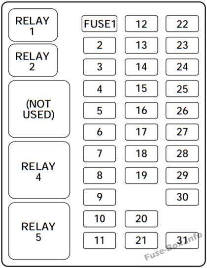
Passenger compartment
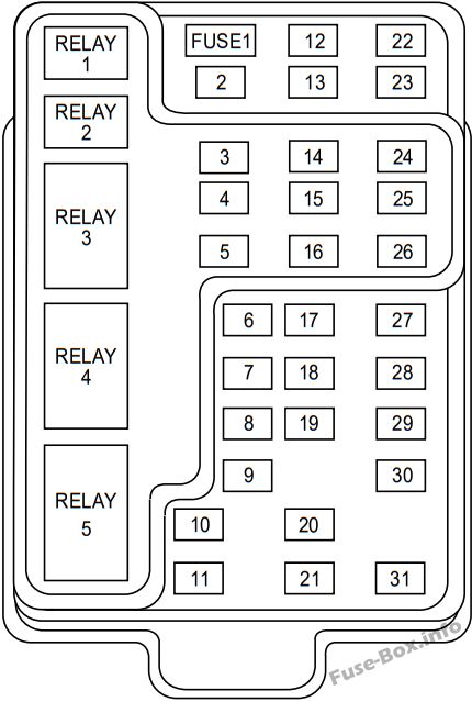
The fuse panel is located below and to the left of the steering wheel by the brake pedal behind the cover.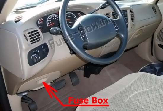
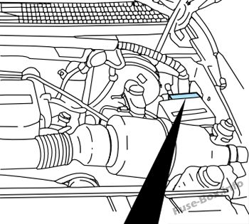
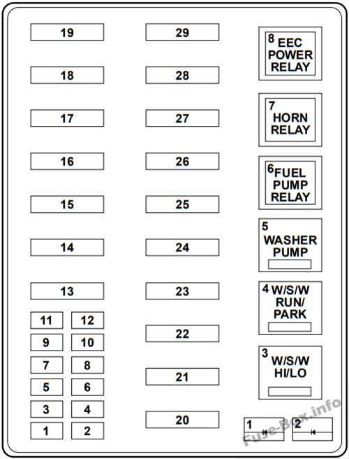
Engine compartment
The power distribution box is located in the engine compartment (left-side).
1997-1998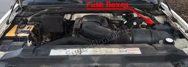
Primary battery fuses (megafuses)
Primary battery fuses are located under the PRIMARY BATTERY FUSE cover next to starter relay.
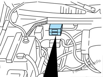
Engine minifuse panel
The minifuse panel is located behind the power distribution box.
1999-2003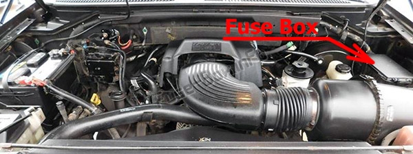
Fuse box diagrams
1997
Passenger compartment
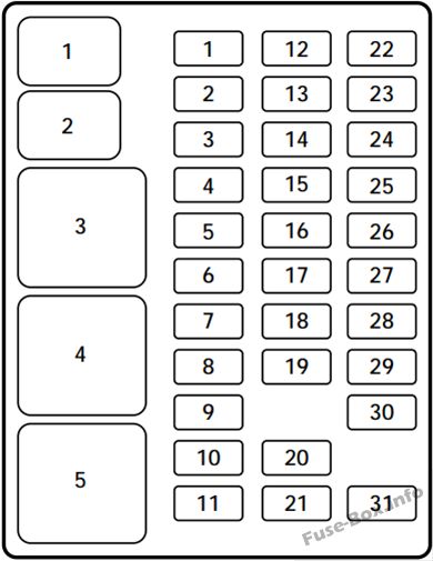
Assignment of the fuses in the Passenger compartment (1997)
| Position | Amps | Description |
|---|---|---|
| 1 | 15 | Stop/turn lamps and turn indicators |
| 2 | 5 | Instrument cluster |
| 3 | 25 | Cigarette lighter |
| 4 | 5 | Power mirrors, autolamp, remote anti-theft/keyless entry, headlamp relay and parking lamp relay |
| 5 | 15 | Speed control, daytime running lamps, climate control blend door, backup lamps, A/C clutch coil |
| 6 | 5 | Brake-shift interlock, generic electronic module (GEM)/central timer module (CTM) and air suspension module |
| 7 | – | Not used |
| 8 | 5 | Radio, remote anti-theft/keyless entry, GEM module/CTM module |
| 9 | – | Not used |
| 10 | – | Not used |
| 11 | 30 | Wiper system |
| 12 | 5 | On-board diagnostic (OBD II) data link connector |
| 13 | 15 | Brake ON/OFF switch, rear anti-lock brake module and brake pressure switch |
| 14 | 15 | Interior lamps and accessory delay relay |
| 15 | 5 | GEM module/CTM module |
| 16 | 20 | High beam headlamps |
| 17 | – | Not used |
| 18 | 5 | Instrument illumination |
| 19 | 10 | Air bag diagnostic monitor, instrument cluster |
| 20 | 5 | GEM module/CTM module and powertrain control module (PCM) |
| 21 | 15 | Starter relay |
| 22 | 10 | Air bag diagnostic monitor and passenger air bag deactivate switch |
| 23 | 10 | 4WD clutch relay, electronic flasher, 4WD/2WD vacuum solenoids and trailer tow battery charge relay |
| 24 | 10 | I/P blower relay |
| 25 | 5 | 4WABS module and relay |
| 26 | 10 | Right low beam headlamp and DRL module |
| 27 | 5 | Foglamp relay |
| 28 | 10 | Left low beam headlamp |
| 29 | 5 | Autolamp, instrument cluster, transmission control indicator lamp and switch |
| 30 | 30 | Ignition coils and PCM relay |
| 31 | – | Not used |
| 1 | Interior lamps relay | |
| 2 | Battery saver relay | |
| 3 | Not used | |
| 4 | One touch down relay | |
| 5 | Accessory delay relay |
Engine compartment
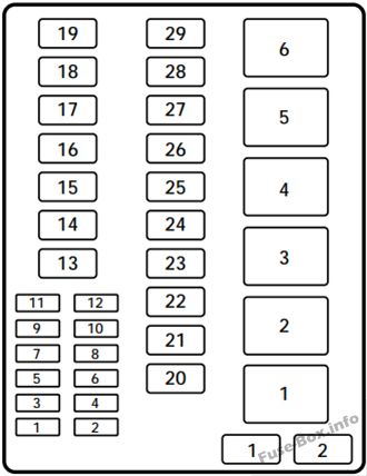
Assignment of the fuses in the Power distribution box (1997)
| Position | Amps | Description |
|---|---|---|
| 1 | 20 | Trailer tow back-up and tail lamps |
| 2 | 10 | Air bag diagnostic monitor |
| 3 | 15 | Power locks |
| 4 | 15 | Air suspension |
| 5 | 20 | Horn |
| 6 | 15 | Audio system |
| 7 | 15 | Parking and tail lamps |
| 8 | 30 | Headlamps |
| 9 | 15 | Daytime running lamps and fog lamps |
| 10 | 25 | Auxiliary power point |
| 11 | – | Not used |
| 12 | – | Not used |
| 13 | – | Not used |
| 14 | 60/20 | 4WABS/rear anti-lock brake |
| 15 | 50 | Air suspension compressor |
| 16 | 40 | Trailer tow battery charge and stop/turn lamps |
| 17 | 30 | 4WD transfer case shift motor and clutch |
| 18 | 30 | Driver power seat |
| 19 | 20 | Fuel pump |
| 20 | 50 | Instrument panel fuse panel ignition switch feed |
| 21 | 50 | Instrument panel fuse panel ignition switch feed |
| 22 | 50 | I/P fuse panel battery feed |
| 23 | 40 | I/P blower |
| 24 | 30 | PCM power |
| 25 | 30 | Power windows |
| 26 | – | Not used |
| 27 | – | Not used |
| 28 | 30 | Trailer tow electronic brake |
| 29 | – | Not used |
| 1 | Rear ABS diode | |
| 2 | PCM diode | |
| 1 | Windshield wipers HI/LO speed | |
| 2 | Windshield wipers run/park relay | |
| 3 | Washer pump relay | |
| 4 | Fuel pump relay | |
| 5 | Horn relay | |
| 6 | PCM power relay |
Primary battery fuses (megafuses)
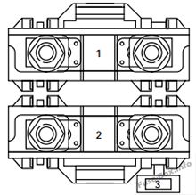
| Location | Amperage | Description |
|---|---|---|
| 1 | 175 | Power network box megafuse |
| 2 | 175 | Alternator megafuse |
| 3 | 20 | Alternator field minifuse |
Engine minifuse panel
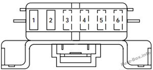
| Location | Amperage | Description |
|---|---|---|
| 1 | 5 | Powertrain control module (PCM) |
| 2 | 20 | Trailer tow stop/turn lamps |
| 3 | – | Not used |
| 4 | – | Not used |
| 5 | – | Not used |
| 6 | – | Not used |
1998
Passenger compartment
Assignment of the fuses in the Passenger compartment (1998)
| № | Amp Rating | Description |
|---|---|---|
| 1 | 15A | Flasher Relay |
| 2 | 5A | Instrument Cluster |
| 3 | 25A | Cigar Lighter |
| 4 | 5A | Park Lamp Relay, Headlamp Relay, Autolamp Module Remote Anti-Theft Personality (RAP) Module, Power Mirror Switch |
| 5 | 15A | Digital Transmission Range (DTR) Sensor (A/T), Backup Lamp Switch (M/T), Daytime Running Lights (DRL) Module, Speed Control Servo/Amplifier Assembly, Heater-A/C Control Assembly, Blend Door Actuator |
| 6 | 5A | Shift Lock Actuator, Generic Electronic Module (GEM), Rear Air Suspension (RAS) Module |
| 7 | — | Not Used |
| 8 | 5A | Radio, Main Light Switch, Remote Anti-Theft Personality (RAP) Module |
| 9 | — | Not Used |
| 10 | — | Not Used |
| 11 | 30A | Washer Pump Relay, Wiper Run/Park Relay, Wiper Hi/LO Relay, Windshield Wiper Motor |
| 12 | 5A | Data Link Connector (DLC) |
| 13 | 15A | Rear Anti-Lock Brake System (RABS) Module, Brake On/Off (BOO) Switch, Brake Pressure Switch |
| 14 | 15A | Batteiy Saver Relay, Interior Lamp Relay |
| 15 | 5A | Generic Electronic Module (GEM) |
| 16 | 20A | Instrument Cluster (W/O DRL), Daytime Running Lamps (DRL) Module, Hi-Beam Headlamps (Power supplied through Multi-Function Switch) |
| 17 | — | Not Used |
| 18 | 5A | Park Lamp Relay, Trailer Electronic Brake Controller, Main Light Switch, Trailer Tow Run Relay, Front Park/Turn Lamps, License Lamps, Stop/Park/Turn Lamps, Tail/Side Marker Lamps (Power supplied through Main Light Switch) |
| 19 | 10A | Instrument Cluster, Air Bag Diagnostic Monitor |
| 20 | 5A | Powertrain Control Module (PCM), Generic Electronic Module (GEM)/Central Timer Module (CTM) |
| 21 | 15A | Clutch Pedal Position (CPP) Switch (W/O RAP), Starter Interrupt Relay (W/RAP) |
| 22 | 10A | Air Bag Diagnostic Monitor, Passive De-Activation (PAD) Module |
| 23 | 10A | Trailer tow Batteiy Charge Relay, 4X4 Hub Solenoid, 4X2 Hub Solenoid, Flasher Relay, Shift on the Fly Relay |
| 24 | 10A | Blower Relay |
| 25 | 5A | 4 Wheel Anti-Lock Brake System (4WABS) Module, 4WABS Relay |
| 26 | 10A | Daytime Running Lamps (DRL) Module, Right Headlamp |
| 27 | 5A | Main Light Switch, Fog Lamp Relay |
| 28 | 10A | Left Headlamp |
| 29 | 5A | Autolamp Module, Instrument Cluster, Transmission Control Switch (TCS), Brake Warning Resistor/Diode Assembly (W/RABS) |
| 30 | 30A | Radio Noise Capacitor, Ignition Coil, PCM Power Diode |
| 31 | — | Not Used |
| Relay 1 | — | Interior Lamp Relay |
| Relay 2 | — | Batteiy Saver Relay |
| Not Used | — | Not Used |
| Relay 4 | — | One Touch Down Relay |
| Relay 5 | — | ACC Delay Relay |
Engine compartment
Assignment of the fuses in the Power distribution box (1998)
| № | Amp Rating | Description |
|---|---|---|
| 4 | 15 A* | Rear Air Suspension (RAS) |
| 5 | 20A* | Horn Relay |
| 6 | 15 A* | Radio, Premium Sound Amplifier, CD Changer |
| 7 | 15 A* | Main Light Switch, Park Lamp Relay |
| 8 | 30A* | Main Light Switch, Headlamp Relay, Multi-Function Switch |
| 9 | 15 A* | Daytime Running Lamps (DRL) Module, Fog Lamp Relay |
| 10 | 25A* | Auxiliary Power Socket |
| 11 | — | Not Used |
| 12 | — | Not Used |
| 13 | — | Not Used |
| 14 | 60A**/20A** | 4 Wheel Anti-Lock Brake System (4WABS) Module/Ignition Switch (W/RABS Only) |
| 15 | 50A** | Rear Air Suspension Compressor |
| 16 | 40A** | Trailer Tow Batteiy Charge Relay, Engine Fuse Module (Fuse 2) |
| 17 | 30A** | Shift on the Fly Relay, Transfer Case Shift Relay |
| 18 | 30A** | Power Seat Control Switch |
| 19 | 20A** | Fuel Pump Relay |
| 1 | 20A * | Trailer Tow Running Lamp Relay, Trailer Tow Backup Lamp Relay |
| 2 | 10 A* | Air Bag Diagnostic Monitor |
| 3 | 15 A* | All Unlock Relay, All Lock Relay, Driver Unlock Relay, LH Power Door Lock Switch, RH Power Door Lock Switch |
| 20 | 50A** | Ignition Switch |
| 21 | 50A** | Ignition Switch |
| 22 | 50A** | Junction Box Fuse/Relay Panel Batteiy Feed |
| 23 | 40A** | Blower Relay |
| 24 | 30A** | PCM Power Relay, Engine Fuse Module (Fuse 1) |
| 25 | 30A** | Junction Box Fuse/Relay Panel, ACC Delay Relay |
| 26 | — | Not Used |
| 27 | — | Not Used |
| 28 | 30A** | Trailer Electronic Brake Controller |
| 29 | — | Not Used |
| * Mini fuses ** Maxi fuses |
1999
Passenger compartment
Assignment of the fuses in the Passenger compartment (1999)
| № | Amp Rating | Description |
|---|---|---|
| 1 | 15A | Audio |
| 2 | 5A | Powertrain Control Module (PCM), Cluster |
| 3 | 20A | Cigar Lighter, OBD-II Scan Tool Connector |
| 4 | 15A | Autolamp Module, Remote Entry Module, Mirrors |
| 5 | 15A | AC Clutch Relay, Speed Control Module, Reverse Lamp, Climate Mode Switch, Daytime Running Lamp Relay |
| 6 | 5A | Cluster, Brake Shift Interlock Solenoid, Rear Air Suspension Module, GEM Module |
| 7 | — | Not Used |
| 8 | 5A | Radio, Remote Entry Module, GEM Module |
| 9 | — | Not Used |
| 10 | — | Not Used |
| 11 | 30A | Front Washer Pump Relay, Wiper Run/Park Relay, Wiper Hi/LO Relay, Windshield Wiper Motor |
| 12 | — | Not Used |
| 13 | 20A | Stop Lamp Switch (Lamps), Turn/Hazard Flasher, Speed Control Module |
| 14 | 15A | Battery Saver Relay, Interior Lamp Relay, Accessory Delay Relay (Power Windows) |
| 15 | 5A | Stop Lamp Switch, (Speed Control, Brake Shift Interlock, ABS, PCM Module Inputs), GEM Module, RABS Test Connector |
| 16 | 20A | Headlamps (Hi Beams), Cluster (Hi Beam Indicator) |
| 17 | — | Not Used |
| 18 | 5A | Instrument Illumination (Dimmer Switch Power) |
| 19 | — | Not Used |
| 20 | 5A | Audio, GEM Module, Powertrain Control Module (PCM), |
| 21 | 15A | Starter Relay, Clutch Switch, Fuse 20 |
| 22 | 10A | Air Bag Module, Passenger Airbag Deactivation Module |
| 23 | 10A | Trailer Tow Battery Charge Relay, Turn/Hazard Flasher, 4×4 Solenoids, 4×4 Relays |
| 24 | 10A | Climate Mode Switch (Blower Relay) |
| 25 | 5A | 4 Wheel Anti-Lock Brake System (4WABS) Module |
| 26 | 10A | Right Side Low Beam Headlamp |
| 27 | 5A | Foglamp Relay and Foglamp Indicator |
| 28 | 10A | Left Side Low Beam Headlamp |
| 29 | 5A | Autolamp Module, Transmission Overdrive Control Switch |
| 30 | 30A | Passive Anti Theft Transceiver, Cluster, Ignition Coils, Powertrain Control Module Relay |
| 31 | — | Not Used |
| Relay 1 | — | Interior Lamp Relay |
| Relay 2 | — | Battery Saver Relay |
| Relay 4 | — | One Touch Down Window Relay |
| Relay 5 | — | ACC Delay Relay |
Engine compartment
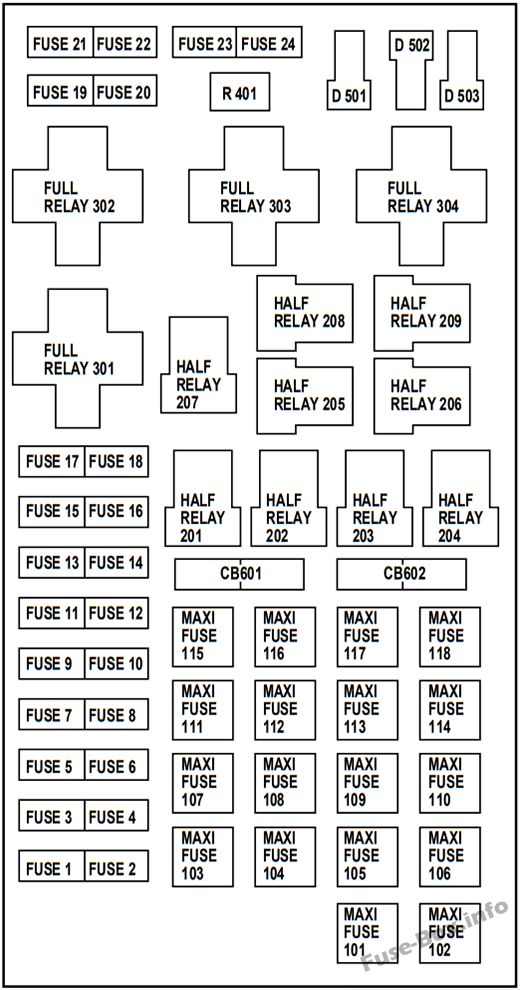
Assignment of the fuses in the Power distribution box (1999)
| № | Amp Rating | Description |
|---|---|---|
| 1 | 25A * | Power Point |
| 2 | 30A* | Powertrain Control Module |
| 3 | 30A* | Headlamps/Autolamps |
| 4 | 15 A* | Air Suspension |
| 5 | 20A* | Trailer Tow Backup/Park Lamps |
| 6 | 15 A* | Parklamps/Autolamps |
| 7 | 20A* | Horn |
| 8 | 15 A* | Power Door Locks |
| 9 | 15 A* | Daytime Running Lamps (DRL), Fog Lamps |
| 10 | 20A* | Fuel Pump |
| 11 | 20A* | Alternator Field |
| 12 | — | Not Used |
| 13 | — | Not Used |
| 14 | — | Not Used |
| 15 | — | Not Used |
| 16 | — | Not Used |
| 17 | — | Not Used |
| 18 | 15 A* | Powertrain Control Module, Fuel Injectors, Fuel Pump, Mass Air Flow Sensor |
| 19 | 10 A* | Trailer Tow Stop and Right Turn Lamp |
| 20 | 10 A* | Trailer Tow Stop and Left Turn Lamp |
| 21 | — | Not Used |
| 22 | — | Not Used |
| 23 | 15 A* | Powertrain Control Module, HEGO Sensor, Canister Vent |
| 24 | 15 A* | Powertrain C ontrol Module, Automatic Transmission, CMS Sensor |
| 101 | 30A** | Trailer Tow Battery Charge |
| 102 | 50/20A** | Four Wheel Antilock Brake Module/Rear Wheel Antilock Brake Module |
| 103 | 50A* | Junction Block Battery Feed |
| 104 | 30A** | 4×4 Shift Motor & Clutch |
| 105 | 40A** | Climate Control Front Blower |
| 106 | — | Not Used |
| 107 | — | Not Used |
| 108 | 30A** | Trailer Tow Electric Brake |
| 109 | 50A** | Air Suspension Compressor |
| 110 | 30A** | Power Windows |
| 111 | 50A** | Ignition Switch Battery Feed (Start and Run Circuits) |
| 112 | 30A** | Drivers Power Seat |
| 113 | 50A** | Ignition Switch Battery Feed (Run and Accessory Circuits) |
| 114 | — | Not Used |
| 115 | — | Not Used |
| 116 | — | Not Used |
| 117 | — | Not Used |
| 118 | — | Not Used |
| 201 | — | Trailer Tow Park Lamp Relay |
| 202 | — | Front Wiper Run/Park Relay |
| 203 | — | Trailer Tow Backup Lamp Relay |
| 204 | — | A/C Clutch Relay |
| 205 | — | Horn Relay |
| 206 | — | Fog Lamp Relay |
| 207 | — | Front Washer Pump Relay |
| 208 | — | Not Used |
| 209 | — | Front Wiper Hi/Lo Relay |
| 301 | — | Fuel Pump Relay |
| 302 | — | Trailer Tow Battery Charge Relay |
| 303 | — | Rear Air Suspension Relay |
| 304 | — | Powertrain Control Module Relay |
| 401 | — | Not Used |
| 501 | — | Powertrain Control Module Diode |
| 502 | — | A/C Clutch Diode |
| 503 | — | Not Used |
| 601 | — | Not Used |
| 602 | — | Not Used |
| * Mini fuses ** Maxi fuses |
2000
Passenger compartment
Assignment of the fuses in the Passenger compartment (2000)
| № | Amp Rating | Description |
|---|---|---|
| 1 | 15A | Audio |
| 2 | 5A | Powertrain Control Module (PCM), Cluster |
| 3 | 20A | Cigar Lighter, OBD-II Scan Tool Connector |
| 4 | 5A | Remote Entry Module, Mirrors |
| 5 | 15A | Speed Control Module, Reverse Lamp, Climate Mode Switch, Daytime Running Lamp Relay |
| 6 | 5A | Cluster, Brake Shift Interlock Solenoid, GEM Module |
| 7 | — | Not Used |
| 8 | 5A | Radio, Remote Entry Module, GEM Module |
| 9 | — | Not Used |
| 10 | — | Not Used |
| 11 | 30A | Front Washer Pump Relay, Wiper Run/Park Relay, Wiper Hi/LO Relay, Windshield Wiper Motor |
| 12 | — | Not Used |
| 13 | 20A | Stop Lamp Switch (Lamps), Turn/Hazard Flasher, Speed Control Module |
| 14 | 15A | Battery Saver Relay, Interior Lamp Relay, Accessoiy Delay Relay (Power Windows) |
| 15 | 5A | Stop Lamp Switch, (Speed Control, Brake Shift Interlock, ABS, PCM Module Inputs), GEM Module, RABS Test Connector |
| 16 | 20A | Headlamps (Hi Beams), Cluster (Hi Beam Indicator) |
| 17 | — | Not Used |
| 18 | 5A | Instrument Illumination (Dimmer Switch Power) |
| 19 | — | Not Used |
| 20 | 5A | Audio, GEM (or CTM) Module, Powertrain Control Module (PCM), |
| 21 | 15A | Starter Relay, Clutch Switch, Fuse 20 |
| 22 | 10A | Air Bag Module, Passenger Airbag Deactivation Module, Climate Mode Switch (Blower Relay) |
| 23 | 10A | Trailer Tow Battery Charge Relay, Turn/Hazard Flasher, 4×4 Solenoids, 4×4 Relays, Overhead Console, 4 Wheel Anti-Lock Brake System (4WABS) Module |
| 24 | — | Not Used |
| 25 | — | Not Used |
| 26 | 10A | Right Side Low Beam Headlamp |
| 27 | 5A | Foglamp Relay and Foglamp Indicator |
| 28 | 10A | Left Side Low Beam Headlamp |
| 29 | 5A | Autolamp Module, Transmission Overdrive Control Switch |
| 30 | 30A | Passive Anti Theft Transceiver, Cluster, Ignition Coils, Powertrain Control Module Relay |
| 31 | — | Not Used |
| Relay 1 | — | Interior Lamp Relay |
| Relay 2 | — | Battery Saver Relay |
| Relay 3 | — | Not Used |
| Relay 4 | — | One Touch Down Window Relay |
| Relay 5 | — | ACC Delay Relay |
Engine compartment
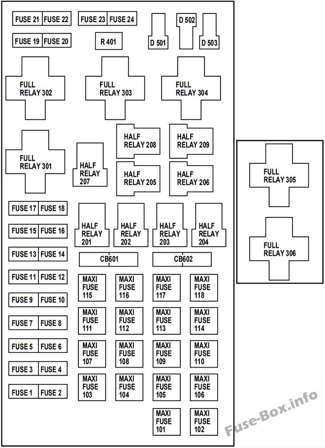
Assignment of the fuses in the Power distribution box (2000)
| № | Amp Rating | Description |
|---|---|---|
| 1 | 20A * | Power Point |
| 2 | 30A* | Powertrain Control Module |
| 3 | 30A* | Headlamps/Autolamps |
| 4 | — | Not Used |
| 5 | 20A* | Trailer Tow Backup/Park Lamps |
| 6 | 15 A* | Parklamps/Autolamps, Passenger Fuse Panel Feed Fuse #18 |
| 7 | 20A* | Horn |
| 8 | 15 A* | Power Door Locks |
| 9 | 15 A* | Daytime Running Lamps (DRL), Fog Lamps |
| 10 | 20A* | Fuel Pump |
| 11 | 20A* | Alternator Field |
| 12 | 20A* | Rear Auxiliary Power Point |
| 13 | 15 A* | A/C Clutch |
| 14 | — | Not Used |
| 15 | — | Not Used |
| 16 | — | Not Used |
| 17 | — | Not Used |
| 18 | 15 A* | Powertrain Control Module, Fuel Injectors, Fuel Pump Relay, Idle Air Control, Mass Air Flow Sensor |
| 19 | 10 A* | Trailer Tow Stop and Right Turn Lamp |
| 20 | 10 A* | Trailer Tow Stop and Left Turn Lamp |
| 21 | — | Not Used |
| 22 | — | Not Used |
| 23 | 15 A* | HEGO Sensor, Canister Vent, Automatic Transmission, CMS Sensor |
| 24 | — | Not Used |
| 101 | 30A** | Trailer Tow Battery Charge |
| 102 | 50/20A** | Four Wheel Antilock Brake Module/Rear Wheel Antilock Brake Module |
| 103 | 50A** | Junction Block Battery Feed |
| 104 | 30A** | 4×4 Shift Motor & Clutch |
| 105 | 40A** | Climate Control Front Blower |
| 106 | 20A** | Inter Cooler Pump (Lightning only) |
| 107 | — | Not Used |
| 108 | 30A** | Trailer Tow Electric Brake |
| 109 | — | Not Used |
| 110 | 30A** | Power Windows |
| 111 | 40A** | Ignition Switch Battery Feed (Start and Run Circuits) |
| 112 | 30A** | Drivers Power Seat, Adjustable Pedals |
| 113 | 40A** | Ignition Switch Battery Feed (Run and Accessory Circuits) |
| 114 | — | Not Used |
| 115 | 20A** | Power Door Locks (SuperCrew only) |
| 116 | — | Not Used |
| 117 | — | Not Used |
| 118 | — | Not Used |
| 201 | — | Trailer Tow Park Lamp Relay |
| 202 | — | Front Wiper Run/Park Relay |
| 203 | — | Trailer Tow Backup Lamp Relay |
| 204 | — | A/C Clutch Relay |
| 205 | — | Horn Relay |
| 206 | — | Fog Lamp Relay |
| 207 | — | Front Washer Pump Relay |
| 208 | — | Inter Cooler Pump Relay (Lightning only) |
| 209 | — | Front Wiper Hi/Lo Relay |
| 301 | — | Fuel Pump Relay |
| 302 | — | Trailer Tow Battery Charge Relay |
| 303 | — | Not Used |
| 304 | — | Powertrain Control Module Relay |
| 305 | — | Fuel Pump Hi/Lo Relay (Lightning only) |
| 306 | — | Inertia Switch Relay (Lightning only) |
| 401 | — | Not Used |
| 501 | — | Powertrain Control Module Diode |
| 502 | — | A/C Compressor Diode |
| 503 | — | Not Used |
| 601 | CB | Power Windows, Moonroof (SuperCrew only) |
| 602 | — | Not Used |
| * Mini fuses ** Maxi fuses |
2001
Passenger compartment
Assignment of the fuses in the Passenger compartment (2001)
| № | Amp Rating | Description |
|---|---|---|
| 1 | 15A | Audio |
| 2 | 5A | Powertrain Control Module (PCM), Cluster |
| 3 | 20 A | Cigar Lighter, OBD-II Scan Tool Connector |
| 4 | 5A | Remote Entry Module, Mirrors |
| 5 | 15A | Speed Control Module, Reverse Lamp, Climate Mode Switch, Daytime Running Lamp Relay |
| 6 | 5A | Cluster, Brake Shift Interlock Solenoid, GEM Module |
| 7 | — | Not Used |
| 8 | 5A | Radio, Remote Entry Module, GEM Module |
| 9 | — | Not Used |
| 10 | — | Not Used |
| 11 | 30A | Front Washer Pump Relay, Wiper Run/Park Relay, Wiper Hi/LO Relay, Windshield Wiper Motor |
| 12 | — | Not Used |
| 13 | 20 A | Stop Lamp Switch (Lamps), Turn/Hazard Flasher, Speed Control Module |
| 14 | 15A | Battery Saver Relay, Interior Lamp Relay, Accessory Delay Relay (Power Windows) |
| 15 | 5A | Stop Lamp Switch, (Speed Control, Brake Shift Interlock, ABS, PCM Module Inputs), GEM Module |
| 16 | 20 A | Headlamps (Hi Beams), Cluster (Hi Beam Indicator) |
| 17 | — | Not Used |
| 18 | 5A | Instrument Illumination (Dimmer Switch Power) |
| 19 | — | Not Used |
| 20 | 5A | Audio, GEM (or CTM) Module, Powertrain Control Module (PCM), |
| 21 | 15A | Starter Relay, Fuse 20 |
| 22 | 10A | Air Bag Module, Climate Mode Switch (Blower Relay) |
| 23 | 10A | Trailer Tow#k8SjZc9Dxk Battery Charge Relay, Turn/Hazard Flasher, 4×4 Solenoids, 4×4 Relays, Overhead Console, 4 Wheel Anti-Lock Brake System (4WABS) Module |
| 24 | — | Not Used |
| 25 | — | Not Used |
| 26 | 10A | Right Side Low Beam Headlamp |
| 27 | 5A | Foglamp Relay and Foglamp Indicator |
| 28 | 10A | Left Side Low Beam Headlamp |
| 29 | 5A | Autolamp Module, Transmission Overdrive Control Switch |
| 30 | 30A | Passive Anti Theft Transceiver, Cluster, Ignition Coils, Powertrain Control Module Relay |
| 31 | — | Not Used |
| Relay 1 | — | Interior Lamp Relay |
| Relay 2 | — | Battery Saver Relay |
| Relay 3 | — | Not Used |
| Relay 4 | — | One Touch Down Window Relay |
| Relay 5 | — | ACC Delay Relay |
Engine compartment
Assignment of the fuses in the Power distribution box (2001)
| № | Amp Rating | Description |
|---|---|---|
| 17 | — | Not Used |
| 18 | 15 A* | Powertrain Control Module, Fuel Injectors, Fuel Pump Relay, Idle Air Control, Mass Air Flow Sensor |
| 19 | 10 A* | Trailer Tow Stop and Right Turn Lamp |
| 20 | 10 A* | Trailer Tow Stop and Left Turn Lamp |
| 21 | — | Not Used |
| 22 | — | Not Used |
| 23 | 15 A* | HEGO Sensor, Canister Vent, Automatic Transmission, CMS Sensor |
| 24 | — | Not Used |
| 101 | 30A** | Trailer Tow Battery Charge |
| 102 | 50A** | Four Wheel Antilock Brake Module |
| 103 | 50A** | Junction Block Battery Feed |
| 104 | 30A** | 4×4 Shift Motor & Clutch |
| 105 | 40A** | Climate Control Front Blower |
| 106 | — | Not Used |
| 107 | — | Not Used |
| 108 | 30A** | Trailer Tow Electric Brake |
| 109 | — | Not Used |
| 110 | — | Not Used |
| 111 | 40A** | Ignition Switch Battery Feed (Start and Run Circuits) |
| 112 | 30A** | Drivers Power Seat, Adjustable Pedals |
| 113 | 40A** | Ignition Switch Battery Feed (Run and Accessory Circuits) |
| 114 | — | Not Used |
| 115 | 20A** | Power Door Locks |
| 116 | — | Not Used |
| 117 | — | Not Used |
| 118 | — | Not Used |
| 201 | — | Trailer Tow Park Lamp Relay |
| 1 | 20A * | Power Point |
| 2 | 30A* | Powertrain Control Module |
| 3 | 30A* | Headlamps/Autolamps |
| 4 | — | Not Used |
| 5 | 20A* | Trailer Tow Backup/Park Lamps |
| 6 | 15 A* | Parklamps/Autolamps, Passenger Fuse Panel Feed Fuse #18 |
| 7 | 20A* | Horn |
| 8 | — | Not Used |
| 9 | 15 A* | Daytime Running Lamps (DRL), Fog Lamps |
| 10 | 20A* | Fuel Pump |
| 11 | 20A* | Alternator Field |
| 12 | 20A* | Rear Auxiliary Power Point |
| 13 | 15 A* | A/C Clutch |
| 14 | — | Not Used |
| 15 | — | Not Used |
| 16 | — | Not Used |
| 202 | — | Front Wiper Run/Park Relay |
| 203 | — | Trailer Tow Backup Lamp Relay |
| 204 | — | A/C Clutch Relay |
| 205 | — | Horn Relay |
| 206 | — | Fog Lamp Relay |
| 207 | — | Front Washer Pump Relay |
| 208 | — | Not Used |
| 209 | — | Front Wiper Hi/Lo Relay |
| 301 | — | Fuel Pump Relay |
| 302 | — | Trailer Tow Battery Charge Relay |
| 303 | — | Not Used |
| 304 | — | Powertrain Control Module Relay |
| 305 | — | Not Used |
| 306 | — | Not Used |
| 401 | — | Not Used |
| 501 | — | Powertrain Control Module Diode |
| 502 | — | A/C Compressor Diode |
| 503 | — | Not Used |
| 601 | 30A CB | Power Windows, Moonroof |
| 602 | — | Not Used |
| * Mini fuses ** Maxi fuses |
2002
Passenger compartment
Assignment of the fuses in the Passenger compartment (2002)
| № | Amp Rating | Description |
|---|---|---|
| 1 | 15A | Audio |
| 2 | 5A | Powertrain Control Module (PCM), Cluster |
| 3 | 20A | Cigar Lighter, Data Link Connector |
| 4 | 5A | Exterior Rear View Mirror Switch, Mirror turn Signal Relays |
| 5 | 15A | Speed Control Module, Reverse Lamp, Climate Mode Switch, Daytime Running Lamp Relay, Digital Transmission Range (DTR) Sensor |
| 6 | 5A | Cluster, Brake Shift Interlock Solenoid, GEM Module |
| 7 | — | Not Used |
| 8 | 5A | Radio, Remote Entry Module, GEM Module, In-vehicle entertainment system (SuperCrew only) |
| 9 | — | Not Used |
| 10 | — | Not Used |
| 11 | 30A | Front Washer Pump Relay, Wiper Run/Park Relay, Wiper Hi/LO Relay, Windshield Wiper Motor |
| 12 | — | Not Used |
| 13 | 20A | Stop Lamp Switch (Lamps), Turn/Hazard Flasher |
| 14 | 15A | Battery Saver Relay, Interior Lamp Relay |
| 15 | 5A | Stop Lamp Switch, (Speed Control, Brake Shift Interlock), GEM Module, RABS Module |
| 16 | 20A | Headlamps (Hi Beams), Cluster (Hi Beam Indicator) |
| 17 | — | Not Used |
| 18 | 5A | Instrument Illumination (Dimmer Switch Power) |
| 19 | — | Not Used |
| 20 | 5A | Audio, GEM Module, Powertrain Control Module (PCM), Transmission Range Sensor |
| 21 | 15A | Digital Transmission Range (DTR) Sensor, Clutch Switch, Starter Relay, I/P fuse 20 |
| 22 | 10A | Air Bag Module, Passenger Airbag Deactivation Module |
| 23 | 10A | Trailer Tow Battery Charge Relay, Turn/Hazard Flasher, 4×4 Solenoids, 4×4 Relays, Overhead Console, 4 Wheel Anti-Lock Brake System (4WABS) Module, EC Mirror, Heated Seats |
| 24 | 10A | Function Selector Switch Assembly |
| 25 | — | Not Used |
| 26 | 10A | Right Side Low’ Beam Headlamp |
| 27 | 5A | Foglamp Relay and Foglamp Indicator, Main Light Switch (upstream) |
| 28 | 10A | Left Side Low Beam Headlamp |
| 29 | 5A | Autolamp Module, Transmission Overdrive Control Switch, Central Security Module,Belt Minder |
| 30 | 30A | Passive Anti Theft Transceiver, Cluster, Ignition Coils, Powertrain Control Module Relay, Coil on Plugs, Radio Noise Capacitor, ECC Diode |
| 31 | — | Not Used |
| Relay 1 | — | Interior Lamp Relay |
| Relay 2 | — | Battery’ Saver Relay |
| Relay 3 | — | Not Used |
| Relay 4 | — | One Touch Down Window’ Relay |
| Relay 5 | — | ACC Delay Relay |
Engine compartment
Assignment of the fuses in the Power distribution box (2002)
| № | Amp Rating | Description |
|---|---|---|
| 1 | 20A * | Power Point |
| 2 | 30 A* | Powertrain Control Module |
| 3 | 30 A* | Main Light Switch, Headlamp Relay, Multifunction Switch |
| 4 | — | Not Used |
| 5 | 20 A* | Trailer Tow Backup/Park Lamps |
| 6 | 15 A* | Main Light Switch, Park Lamp Relay |
| 7 | 20 A* | Horn |
| 8 | 15 A* | Power Door Locks, CSM, Lock Relays |
| 9 | 15 A* | Daytime Running Lamps (DRL), Fog Lamps |
| 10 | 20 A* | Fuel Pump |
| 11 | 20 A* | Alternator Field |
| 12 | 20 A* | Rear Auxiliary Power Point |
| 13 | 15 A* | A/C Clutch |
| 14 | — | Not Used |
| 15 | 10A | Running Board Lamps |
| 16 | — | Not Used |
| 17 | — | Not Used |
| 18 | 15 A* | Powertrain Control Module, Fuel Injectors, Fuel Pump Relay, Mass Air Flow’ Sensor |
| 19 | 10 A* | Trailer/Camper Adapter (Right Stop and Right Turn Lamp) |
| 20 | 10 A* | Trailer/Camper Adapter (Left Stop and Left Turn Lamp) |
| 21 | — | Not Used |
| 22 | — | Not Used |
| 23 | 15 A* | HE GO Sensor, Automatic Transmission |
| 24 | — | Not Used |
| 101 | 30A** | Trailer Tow Battery Charge |
| 102 | 50/20A** | Four Wheel Antilock Brake Module/Rear Wheel Antilock Brake Module, Ignition Switch |
| 103 | 50A** | Central Junction Box |
| 104 | 30A** | 4×4 Shift Motor & Clutch |
| 105 | 40A** | Climate Control Front Blower |
| 106 | 20A** | Inter Cooler Pump (Supercharged engine only) |
| 107 | — | Not Used |
| 108 | 30A** | Trailer Tow Electric Brake |
| 109 | — | Not Used |
| 110 | 30A** | ACC Delay Relay |
| 111 | 40A** | Ignition Switch Battery Feed (Start and Run Circuits) |
| 112 | 30A** | Drivers Power Seat, Adjustable Pedal switch |
| 113 | 40A** | Ignition Switch Battery Feed (Run and Accessory Circuits) |
| 114 | — | Not Used |
| 115 | 20A** | Power Door Locks |
| 116 | — | Not Used |
| 117 | — | Not Used |
| 118 | 30A** | Heated Seats |
| 201 | — | Trailer Tow Park Lamp Relay |
| 202 | — | Front Wiper Run/Park Relay |
| 203 | — | Trailer Tow Backup Lamp Relay |
| 204 | — | A/C Clutch Relay |
| 205 | — | Horn Relay |
| 206 | — | Fog Lamp Relay |
| 207 | — | Front Washer Pump Relay |
| 208 | — | Inter Cooler Pump Relay (Supercharged engine only) |
| 209 | — | Front Wiper Hi/Lo Relay |
| 301 | — | Fuel Pump Relay |
| 302 | — | Trailer Tow Battery Charge Relay |
| 303 | — | Not Used |
| 304 | — | Powertrain Control Module Relay |
| 305 | — | Fuel Pump Hi/Lo Relay (Supercharged engine only) |
| 306 | — | Inertia Switch Relay (Supercharged engine only) |
| 401 | — | Not Used |
| 501 | — | Powertrain Control Module Diode |
| 502 | — | A/C Compressor Diode |
| 503 | — | Not Used |
| 601 | CB | Power Windows, Moonroof |
| 602 | — | Not Used |
| * Mini fuses ** Maxi fuses |
2003
Passenger compartment
Assignment of the fuses in the Passenger compartment (2003)
| № | Amp Rating | Description |
|---|---|---|
| 1 | 15A | Audio |
| 2 | 5A | Powertrain Control Module (PCM), Cluster |
| 3 | 20A | Cigar lighter, Data link connector |
| 4 | 5A | Power mirror switch, Mirror turn signal relays |
| 5 | 15A | Speed control module, Reverse lamp, Climate mode switch, Daytime Running Lamps (DRL) relay, Digital Transmission Range (DTR) sensor |
| 6 | 5A | Cluster, Brake shift interlock solenoid, GEM |
| 7 | — | Not used |
| 8 | 5A | Radio, Remote entry module, GEM, In-vehicle entertainment system (SuperCrew only) |
| 9 | — | Not used |
| 10 | — | Not used |
| 11 | 30A | Front washer pump relay, Wiper run/park relay, Wiper HI/LO relay, Windshield wiper motor |
| 12 | — | Not used |
| 13 | 20A | Stop lamp switch (Lamps), Turn/Hazard flasher |
| 14 | 15A | Battery saver relay, Interior lamp relay |
| 15 | 5A | Stop lamp switch (speed control, brake shift interlock), GEM, Rear Anti-lock Brake System (RABS) module |
| 16 | 20A | Headlamps (hi beams), Cluster (hi beam indicator) |
| 17 | — | Not used |
| 18 | 5A | Instrument illumination (dimmer switch power) |
| 19 | — | Not used |
| 20 | 5A | Audio, GEM, PCM, Transmission range sensor |
| 21 | 15A | DTR sensor, Clutch switch, Starter relay, I/P fuse 20 |
| 22 | 10A | Air bag module, Passenger air bag deactivation module |
| 23 | 10A | Trailer tow battery Charge relay, Turn/Hazard flasher, 4×4 solenoids, 4×4 relays, Overhead console, 4-Wheel Anti-lock Brake System (4WABS) module, EC mirror, Heated seats |
| 24 | 10A | Function selector switch assembly |
| 25 | 10A | Heated mirrors |
| 26 | 10A | Right-hand low beam headlamp |
| 27 | 5A | Foglamp relay and foglamp indicator, Main light switch (upstream) |
| 28 | 10A | Left-hand low beam headlamp |
| 29 | 5A | Autolamp module, Transmission overdrive control switch, Central security module, Beltminder |
| 30 | 30A | Passive Anti-theft transceiver, Cluster, Ignition coils, PCM relay, Coil on plugs, Radio noise capacitor, ECC diode |
| 31 | — | Not used |
| Relay 1 | — | Interior lamp relay |
| Relay 2 | — | Battery saver relay |
| Relay 3 | — | Not used |
| Relay 4 | — | One-touch down window relay |
| Relay 5 | — | Accessoiy delay relay |
Engine compartment
Assignment of the fuses in the Power distribution box (2003)
| № | Amp Rating | Description |
|---|---|---|
| 1 | 20A * | Power point |
| 2 | 30 A* | Powertrain Control Module (PCM) |
| 3 | 30 A* | Main light switch, Headlamp relay, Multifunction switch |
| 4 | 20 A* | Console power point (Harley Davidson only) |
| 5 | 20 A* | Trailer tow back-up/park lamps |
| 6 | 15 A* | Main light switch, Park lamp relay |
| 7 | 20 A* | Horn |
| 8 | 15 A* | Power door locks, Central Security Module (CSM), Lock relays (not used on SuperCrew) |
| 9 | 15 A* | Daytime Running Lamps (DRL), Fog lamps |
| 10 | 20 A* | Fuel pump |
| 11 | 20 A* | Alternator field |
| 12 | 20 A* | Rear auxiliary power point (SuperCrew only) |
| 13 | 15 A* | A/C clutch |
| 14 | — | Not used |
| 15 | 10 A* | Running board lamps |
| 16 | 15 A* | Bi-fuel injector module, fuel selector switch and alternative fuel injectors (Bi-fuel vehicles only) |
| 17 | — | Not used |
| 18 | 15 A* | PCM, Fuel injectors, Fuel pump relay, Mass air flow sensor |
| 19 | 10 A* | Trailer/Camper adapter (right stop/turn lamp) |
| 20 | 10 A* | Trailer/Camper adapter (left stop/turn lamp) |
| 21 | — | Not used |
| 22 | — | Not used |
| 23 | 15 A* | HEGO sensor, Automatic transmission |
| 24 | — | Not used |
| 101 | 30A** | Trailer tow battery charge |
| 102 | 50/20A** | Four-wheel Anti-lock Brake System (4WABS) module/Rear-wheel Anti-lock Brake System (RABS) module, Ignition switch |
| 103 | 50A** | Central junction box |
| 104 | 30A** | 4×4 shift motor & clutch |
| 105 | 40A** | Climate control front blower |
| 106 | 20A** | Intercooler pump (supercharged engine only) |
| 107 | — | Not used |
| 108 | 30A** | Trailer tow electric brake |
| 109 | — | Not used |
| 110 | 30A** | Accessoiy delay relay (Not used on SuperCrew) |
| 111 | 40A** | Ignition switch battery feed (start and run circuits) |
| 112 | 30A** | Drivers power seat, Adjustable pedal switch |
| 113 | 40A** | Ignition switch battery feed (run and accessory circuits) |
| 114 | — | Not used |
| 115 | 20A** | Power door locks (SuperCrew only) |
| 116 | 40A** | Heated backlight |
| 117 | 40A** | Audiophile radio (SuperCrew only) |
| 118 | 30A** | Heated seats |
| 201 | — | Trailer tow park lamp relay |
| 202 | — | Front wiper run/park relay |
| 203 | — | Trailer tow backup lamp relay |
| 204 | — | A/C clutch relay |
| 205 | — | Horn relay |
| 206 | — | Fog lamp relay |
| 207 | — | Front washer pump relay |
| 208 | — | Intercooler pump relay (supercharged engine only) |
| 209 | — | Front wiper HI/LO relay |
| 301 | — | Fuel pump relay |
| 302 | — | Trailer tow battery charge relay |
| 303 | — | Heated backlight relay (SuperCrew only) |
| 304 | — | PCM relay |
| 305 | — | Fuel pump HI/LO relay (supercharged engine only) |
| 306 | — | Inertia switch relay (supercharged engine only) |
| 401 | — | Not used |
| 501 | — | PCM diode |
| 502 | — | A/C compressor diode |
| 503 | — | Not used |
| 601 | CB | Power windows, Moonroof (SuperCrew only) |
| 602 | — | Not used |
| * Mini fuses ** Maxi fuses |


