


Fuse Layout Ford Expedition 1997-2002
Contents

Cigar lighter / power outlet fuses in the Ford Expedition are the fuse №3 (Cigar lighter) in the Instrument panel fuse box, and fuses №10 (Auxiliary instrument panel power point), №11 (Auxiliary console power point) in the Engine compartment fuse box (1997-1998). Since 1999 – fuse №3 (Cigar lighter) in the Instrument panel fuse box, and fuses №1 (Power Point), №4 (Console PowerPoint) in the Engine compartment fuse box.
Table of Contents
Fuse box location
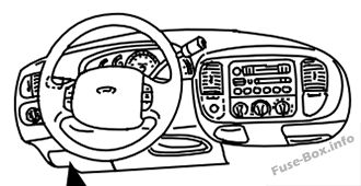
Passenger compartment
The fuse panel is located below and to the left of the steering wheel by the brake pedal.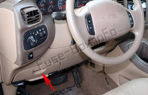
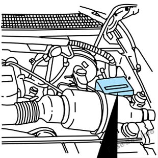
Engine compartment fuse boxes
The power distribution box is located in the engine compartment.
1997-1998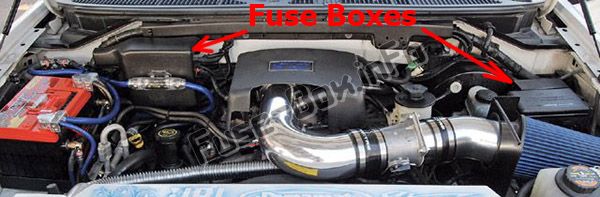
1999-2002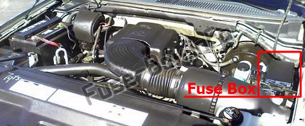
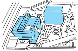
The primary battery fuses (megafuses) are located in the engine compartment near the battery.
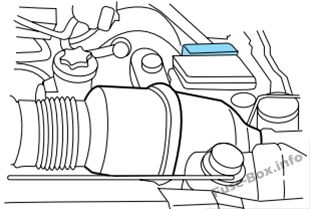
The engine mini fuses are located on the drivers side of the engine compartment.
Fuse box diagrams
1997
Passenger compartment
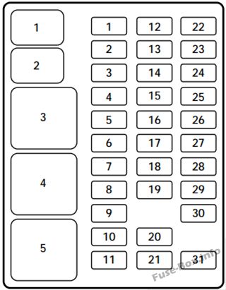
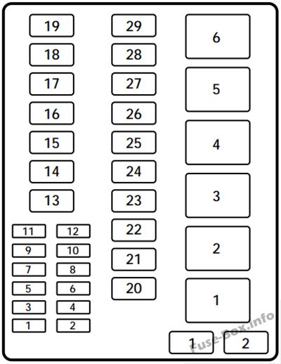
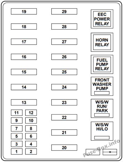
Assignment of the fuses in the Passenger compartment (1997)
| Slot number | Amperage | Description |
|---|---|---|
| 1 | 15 amp | Stop/turn lamps |
| 2 | 5 amp | Instrument cluster, trip computer |
| 3 | 25 amp | Cigar lighter |
| 4 | 5 amp | Autolamp module, head lamp relay, remote entry anti-theft with personality module (RAP), power mirrors |
| 5 | 15 amp | Air condition (A/C) clutch, hybrid fan relay, backup lamps, speed control, DRL, instrument panel blend door actuator, electronic variable orifice (EVO) steering module |
| 6 | 5 amp | Generic electronic module (GEM), shift interlock, air suspension module, heated backlite (HBL) relay, steering sensor, trip computer, compass |
| 7 | 5 amp | Console blower, auxiliary blower relay coil |
| 8 | 5 amp | GEM, radio, RAP module |
| 9 | – | Not used |
| 10 | – | Not used |
| 11 | 30 amp | Front wiper motor, washer motor |
| 12 | 5 amp | OBDII scan tool connector |
| 13 | 15 amp | Brake on/off switch, brake pressure switch |
| 14 | 15 amp | Interior lamps, delayed accessory relay, rear wiper relays |
| 15 | 5 amp | GEM, passive anti-theft system (PATS) module |
| 16 | 20 amp | High beam headlamps, high beam indicator |
| 17 | 10 amp | Heated mirrors, heated mirror switch |
| 18 | 5 amp | Instrument and switch illumination |
| 19 | 10 amp | Airbag diagnostic monitor, instrument cluster |
| 20 | 5 amp | GEM, air suspension module |
| 21 | 15 amp | Starter relay, junction box fuse #20 |
| 22 | 10 amp | Airbag diagnostic monitor |
| 23 | 10 amp | Electronic flasher, 4WD vacuum solenoids, trailer tow battery charge relay, console climate door actuator, auxiliary blend and mode door actuators, auxiliary pot switching module |
| 24 | 10 amp | I/P blower relay, junction fuse box #7 |
| 25 | 5 amp | 4WABS module, 4WABS red lamps relay |
| 26 | 10 amp | Right low beam head lamp, DRL module |
| 27 | 5 amp | Foglamp relay, main lamp switch |
| 28 | 10 amp | Left low beam headlamp |
| 29 | 5 amp | Auto lamp module, instrument cluster, transmission control indicator light and switch |
| 30 | 30 amp | Ignition coils, PCM relay, PATS module, radio capacitors |
| 31 | – | Not used |
| Slot number | Amperage | Description |
| 1 | – | Interior lamp relay |
| 2 | – | Battery saver relay |
| 3 | – | HBL relay |
| 4 | – | One touch down relay |
| 5 | – | Accessory delay relay |
Engine compartment
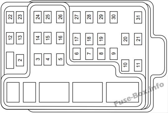
Assignment of the fuses in the Power distribution box (1997)
| Slot number | Amp Rating | Circuits protected |
|---|---|---|
| 1 | 20 amp | Trailer tow backup & tail lamps |
| 2 | 10 amp | Airbag diagnostic monitor |
| 3 | 30 amp | Power locks |
| 4 | 15 amp | Air suspension |
| 5 | 20 amp | Horn |
| 6 | 30 amp | Engine minifuse box fuses #3 and #5 |
| 7 | 15 amp | Park and tail lamps |
| 8 | 30 amp | Headlamps |
| 9 | 15 amp | Fog lamps and DRL |
| 10 | 25 amp | Auxiliary instrument panel (I/P) power point |
| 11 | 25 amp | Auxiliary console power point |
| 12 | 10 amp | Rear wiper |
| 13 | 30 amp | Auxiliary blower |
| 14 | 60 amp | Four wheel anti-lock brake system (4WABS) |
| 15 | 50 amp | Air suspension compressor |
| 16 | 40 amp | Trailer tow battery charge, engine minifuse box fuse #2, engine minifuse box fuse #4 |
| 17 | 30 amp | Four-wheel drive (4WD) transfer case motor and clutch |
| 18 | 30 amp | Driver power seat |
| 19 | 20 amp | Fuel pump |
| 20 | 50 amp | Junction box ignition switched feed |
| 21 | 50 amp | Junction box ignition switched feed |
| 22 | 50 amp | Junction box battery feed |
| 23 | 40 amp | Front blower |
| 24 | 30 amp | Powertrain control module power |
| 25 | 30 C.B. | Windows |
| 26 | – | not used |
| 27 | 40 amp | Heated backlite and mirrors |
| 28 | 30 amp | Trailer tow electric brake |
| 29 | 30 amp | Hybrid fan, moon roof, flip windows |
| Slot number | Description | |
| 1 | – | not used |
| 2 | – | PCM diode |
| Slot number | Description | |
| 1 | – | Windshield wipers high/low speed |
| 2 | – | Windshield wipers run/park |
| 3 | – | Front washer pump relay |
| 4 | – | Fuel pump relay |
| 5 | Horn relay | |
| 6 | – | PCM power relay |
Primary battery fuses (megafuses) (1997)
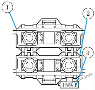
| Location | Amperage | Description |
|---|---|---|
| 1 | 175 | Power Network Box Megafuse |
| 2 | 175 | Alternator Megafuse |
| 3 | 20 | Alternator Field Minifuse |
Engine mini fuse box (1997)
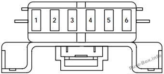
| Slot Number | Amp Rating | Circuits Protected |
|---|---|---|
| 1 | 5 amp | Powertrain Control Module (PCM) |
| 2 | 20 amp | Trailer Tow Stop/Turn Lamps |
| 3 | 10 amp | Audio Rear Integrated Control Panel (RICP), Compact Disc Changer, Radio |
| 4 | 10 amp | Running Board Lamps |
| 5 | 20 amp | Amplifier, Subwoofer Amplifier |
| 6 | — | Not Used |
1998
Passenger compartment
Assignment of the fuses in the Passenger compartment (1998)
| № | Amp Rating | Description |
|---|---|---|
| 1 | 15A | Flasher Relay |
| 2 | 5A | Instrument Cluster, Overhead Trip Computer (OTC) Module |
| 3 | 25A | Cigar Lighter |
| 4 | 5A | Park Lamp Relay, Headlamp Relay, Autolamp Module, Remote Anti-Theft Personality (RAP) Module, Power Mirror Switch |
| 5 | 15A | Digital Transmission Range (DTR) Sensor, Daytime Running Lamps (DRL) Module, Speed Control Servo/Amplifier Assembly, Heater-A/C Control Assembly, Blend Door Actuator, Electronic Variable Orifice (EVO) Module |
| 6 | 5A | Shift Lock Actuator, Generic Electronic Module (GEM), 4 Wheel Air Suspension (4WAS) Module, Compass Sensor, Steering Wheel Rotation Sensor, Heated Grid Relay, Overhead Trip Computer (OTC) Module |
| 7 | 5A | Auxiliary A/C Relay, Console Blower Motor |
| 8 | 5A | Radio, Main Light Switch, Remote Anti-Theft Personality (RAP) Module |
| 9 | — | Not Used |
| 10 | — | Not Used |
| 11 | 30A | Washer Pump Relay, Wiper Run/Park Relay, Wiper Hi/Lo Relay, Windshield Wiper Motor, Rear Wiper Pump Relay |
| 12 | 5A | Data Link Connector (DLC) |
| 13 | 15A | Brake On/Off (BOO) Switch, Brake Pressure Switch |
| 14 | 15A | Battery Saver Relay, Interior Lamp Relay |
| 15 | 5A | Generic Electronic Module (GEM), Passive Anti-Theft System (PATS) Module |
| 16 | 20A | Instrument Cluster (W/O DRL), Daytime Running Lamps (DRL) Module, Hi-Beam Headlamps (Power supplied through Multi-Function Switch) |
| 17 | 10A | Heated Backlight Switch, Left Power/Heated Signal Mirror, Right Power/Heated Signal Mirror |
| 18 | 5A | Main Light Switch, Generic Electronic Module (GEM), Instrument Illumination (Power supplied through Main Light Switch) |
| 19 | 10A | Instrument Cluster, Air Bag Diagnostic Monitor |
| 20 | 5A | 4 Wheel Air Suspension (4WAS), Generic Electronic Module (GEM) |
| 21 | 15A | Digital Transmission Range (DTR) Sensor, Junction Box Fuse/Relay Panel (Fuse 20) |
| 22 | 10A | Air Bag Diagnostic Monitor |
| 23 | 10A | Trailer Tow Battery Charge Relay, 4X4 Center Axle Disconnect solenoid, 4X2 Center Axle Disconnect Solenoid, Function Selector Switch, Rear Integrated Control Panel, Recirculation Vacuum Solenoid, Auxiliary A/C Mode Acturator, Auxiliary A/C Control Module |
| 24 | 10A | Function Selector Swatch |
| 25 | 5A | 4 Wheel Anti-Lock Brake System (4WABS) Module, 4WABS Relay |
| 26 | 10A | Daytime Running Lamps (DRL) Module, Right Headlamp (Power supplied through Multi-Function Switch) |
| 27 | 5A | Main Light Switch, Fog Lamp Relay |
| 28 | 10A | Left Headlamp |
| 29 | 5A | Autolamp Module, Instrument Cluster, Transmission Control Switch (TCS) |
| 30 | 30A | Radio Noise Capacitor, Ignition Coil, PCM Power Diode, Coil On Plugs |
| 31 | — | Not Used |
Engine compartment
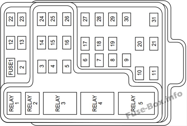
Assignment of the fuses in the Power distribution box (1998)
| № | Amp Rating | Description |
|---|---|---|
| 1 | 20 A* | Trailer Tow Running Lamp Relay, Trailer Tow Backup Lamp Relay |
| 2 | 10A* | Air Bag Diagnostic Monitor |
| 3 | 30 A* | All Unlock Relay, All Lock Relay, Driver’s Unlock Relay |
| 4 | 15A* | Air Suspension Sendee Switch |
| 5 | 20 A* | Horn Relay |
| 6 | 30 A* | Radio, Premium Sound Amplifier, CD Changer, Rear Integrated Control Panel, Sub-Woofer Power (Fuse 3 & Fuse 5) |
| 7 | 15A* | Main Light Switch, Park Lamp Relay |
| 8 | 30 A* | Main Light Switch, Headlamp Relay, Multi-Function Switch |
| 9 | 15A* | Daytime Running Lamps (DRL) Module, Fog Lamp Relay |
| 10 | 25 A* | I/P Auxiliary Power Socket |
| 11 | 25 A* | Console Auxiliary Power Socket |
| 12 | 10A* | Rear Wiper Up Motor Relay, Rear Wiper Down Motor Relay |
| 13 | 30A** | Auxiliary A/C Relay |
| 14 | 60A** | 4 Wheel Anti-Lock Brake System (4WABS) Module |
| 15 | 50A** | Air Suspension Solid State Compressor Relay |
| 16 | 40A** | Trailer Tow Battery Charge Relay, Engine Fuse Module (Fuse 2) |
| 17 | 30A** | Shift on the Fly Relay, Transfer Case Shift relay |
| 18 | 30A** | Power Seat Control Swatch |
| 19 | 20A** | Fuel Pump Relay |
| 20 | 50A** | Ignition Switch (B4 & B5) |
| 21 | 50A** | Ignition Switch (B1 & B3) |
| 22 | 50A** | Junction Box Fuse/Relay Panel Battery Feed |
| 23 | 40A** | I/P Blower Relay |
| 24 | 30A** | PCM Power Relay, Engine Fuse Module (Fuse 1) |
| 25 | 30A CB | Junction Box Fuse/Relay Panel, ACC Delay Relay |
| 26 | — | Not Used |
| 27 | 40A** | Junction Box Fuse/Relay Panel, Heated Grid Relay |
| 28 | 30A** | Trailer Electronic Brake Controller |
| 29 | 30A** | Flip Window Relay, Hybrid Cooling Fan Relay |
| * Mini Fuses ** Maxi Fuses |
Primary battery fuses (megafuses) (1998)
| Location | Amperage | Description |
|---|---|---|
| 1 | 175 | Power Network Box Megafuse |
| 2 | 175 | Alternator Megafuse |
| 3 | 20 | Alternator Field Minifuse |
Engine mini fuse box (1998)
| Slot Number | Amp Rating | Circuits Protected |
|---|---|---|
| 1 | 5 amp | Powertrain Control Module (PCM) |
| 2 | 20 amp | Trailer Tow Stop/Turn Lamps |
| 3 | 10 amp | Audio Rear Integrated Control Panel (RICP), Compact Disc Changer, Radio |
| 4 | 10 amp | Running Board Lamps |
| 5 | 20 amp | Amplifier, Subwoofer Amplifier |
| 6 | — | Not Used |
1999
Passenger compartment
Assignment of the fuses in the Passenger compartment (1999)
| № | Amp Rating | Description |
|---|---|---|
| 1 | 25A | Audio |
| 2 | 5A | Overhead Trip Computer, Electronic Automatic Temperature Control (EATC), Powertrain Control Module (PCM), Cluster |
| 3 | 20A | Cigar Lighter, OBD-II Scan Tool Connector |
| 4 | 15A | Autolamp Module, Remote Entry Module, Mirrors, Air Suspension Switch |
| 5 | 15A | AC Clutch Relay, Speed Control Module, Reverse Lamp, EVO Module, Climate Mode Switch (Front Blower Relay), Daytime Running Lamp Relay |
| 6 | 5A | Cluster, Overhead Trip Computer, Compass, Brake Shift Interlock Solenoid, Air Suspension Module, GEM Module, EVO Steering Sensor |
| 7 | 5A | Aux A/C Blower Relay, Console Blower |
| 8 | 5A | Radio, Remote Entry Module, GEM Module |
| 9 | — | Not Used |
| 10 | — | Not Used |
| 11 | 30A | Front Washer Pump Relay, Wiper Run/Park Relay, Wiper Hi/LO Relay, Windshield Wiper Motor, Rear Washer Pump Relay |
| 12 | — | Not Used |
| 13 | 20A | Stop Lamp Switch (Lamps), Turn/Hazard Flasher, Speed Control Module |
| 14 | 15A | Rear Wipers, Running Board Lamps, Battery Saver Relay, Interior Lamp Relay, Accessoiy Delay Relay (Power Windows) |
| 15 | 5A | Stop Lamp Switch, (Speed Control, Brake Shift Interlock, ABS, PCM Module Inputs), GEM Module |
| 16 | 20A | Headlamps (Hi Beams), Cluster (Hi Beam Indicator) |
| 17 | 10A | Heated Mirrors, Heated Grid Switch Indicator |
| 18 | 5A | Instrument Illumination (Dimmer Switch Power) |
| 19 | — | Not Used |
| 20 | 5A | Audio, Four Wheel Air Suspension (4WAS) Module, GEM Module |
| 21 | 15A | Starter Relay, Fuse 20 |
| 22 | 10A | Air Bag Module |
| 23 | 10A | Aux A/C, Heated Seats, Trailer Tow’ Battery Charge, Turn/Hazard Flasher, Console Blower Door Actuator |
| 24 | 10A | Climate Mode Switch (Blower Relay), EATC (via fuse 7), EATC Blower Relay |
| 25 | 5A | 4 Wheel Anti-Lock Brake System (4WABS) Module |
| 26 | 10A | Right Side Low Beam Headlamp |
| 27 | 5A | Foglamp Relay and Foglamp Indicator |
| 28 | 10A | Left Side Low Beam Headlamp |
| 29 | 5A | Autolamp Module, Transmission Overdrive Control Switch |
| 30 | 30A | Passive Anti Theft Transceiver, Cluster, Ignition Coils, Powertrain Control Module Relay |
| 31 | 10A | Rear Integrated Control Panel (Audio), CD Player |
| Relay 1 | — | Interior Lamp Relay |
| Relay 2 | — | Battery Saver Relay |
| Relay 3 | — | Rear Window Defroster Relay |
| Relay 4 | — | One Touch Down Window Relay |
| Relay 5 | — | ACC Delay Relay |
Engine compartment
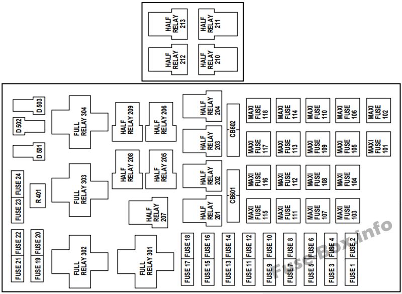
Assignment of the fuses in the Power distribution box (1999)
| № | Amp Rating | Description |
|---|---|---|
| 1 | 25A * | Power Point |
| 2 | 30 A* | Powertrain Control Module |
| 3 | 30 A* | Headlamps/Autolamps |
| 4 | 2 5 A* | Console PowerPoint |
| 5 | 20 A* | Trailer Tow Backup/Park Lamps |
| 6 | 15A* | Parklamps/Autolamps |
| 7 | 20 A* | Horn |
| 8 | 30 A* | Power Door Locks |
| 9 | 15A* | Daytime Running Lamps (DRL), Fog Lamps |
| 10 | 20 A* | Fuel Pump |
| 11 | 20 A* | Alternator Field |
| 12 | 10 A* | Rear Wipers |
| 13 | — | Not Used |
| 14 | — | Not Used |
| 15 | 10 A* | Running Board Lamps |
| 16 | — | Not Used |
| 17 | — | Not Used |
| 18 | 15 A* | Powertrain Control Module, Fuel Injectors, Fuel Pump, Mass Air Flow Sensor |
| 19 | 10 A* | Trailer Tow Stop and Right Turn Lamp |
| 20 | 10 A* | Trailer Tow Stop and Left Turn Lamp |
| 21 | — | Not Used |
| 22 | — | Not Used |
| 23 | 15 A* | Powertrain Control Module, HEGO Sensors, Canister Vent |
| 24 | 15 A* | Powertrain C ontrol Module, Automatic Transmission, CMS Sensor |
| 101 | 30A** | Trailer Tow Battery Charge |
| 102 | 50A** | Four Wheel Antilock Brake Module |
| 103 | 50A** | Junction Block Battery Feed |
| 104 | 30A** | 4×4 Shift Motor & Clutch |
| 105 | 40A** | Climate Control Front Blower |
| 106 | — | Not Used |
| 107 | — | Not Used |
| 108 | 30A** | Trailer Tow Electric Brake |
| 109 | 50A** | Air Suspension Compressor |
| 110 | 30A** | Moonroof, Flip Windows and Heated Seats |
| 111 | 50A** | Ignition Switch Battery Feed (Start Circuit) |
| 112 | 30A** | Drivers Power Seat, Adjustable Pedals |
| 113 | 50A** | Ignition Switch Battery Feed (Run and Accessoiy Circuits) |
| 114 | 30A** | Climate Control Auxiliary Blower |
| 115 | — | Not Used |
| 116 | 40A** | Rear Window Defroster, Heated Mirrors |
| 117 | — | Not Used |
| 118 | — | Not Used |
| 201 | — | Trailer Tow Park Lamp Relay |
| 202 | — | Front Wiper Run/Park Relay |
| 203 | — | Trailer Tow Backup Lamp Relay |
| 204 | — | A/C Clutch Relay |
| 205 | — | Horn Relay |
| 206 | — | Foglamp Relay |
| 207 | — | Front Washer Pump Relay |
| 208 | — | Rear Washer Pump Relay |
| 209 | — | Front Wiper Hi/Lo Relay |
| 210 | — | Not Used |
| 211 | — | Not Used |
| 212 | — | Rear Wiper Up Relay |
| 213 | — | Rear Wiper Down Relay |
| 301 | — | Fuel Pump Relay |
| 302 | — | Trailer Tow Battery Charge Relay |
| 303 | — | Not Used |
| 304 | — | Powertrain Control Module Relay |
| 401 | — | Not Used |
| 501 | — | Powertrain Control Module Diode |
| 502 | — | A/C Clutch Diode |
| 503 | — | Not Used |
| 601 | 30A | Delayed Accessory (Power Windows, Flip Windows, Moonroof) |
| 602 | — | Not Used |
| * Mini fuses ** Maxi fuses |
2000
Passenger compartment
Assignment of the fuses in the Passenger compartment (2000)
| № | Amp Rating | Passenger Compartment Fuse Panel Description |
|---|---|---|
| 1 | 25A | Audio |
| 2 | 5A | Overhead Trip Computer, Electronic Automatic Temperature Control (EATC), Powertrain Control Module (PCM), Cluster |
| 3 | 20 A | Cigar Lighter, OBD-II Scan Tool Connector |
| 4 | 7.5A | Remote Entry Module, Mirrors, Memory Functions (Seats and Pedals) |
| 5 | 15A | Speed Control Module, Reverse Lamp, EVO Module, Climate Mode Switch (Front Blower Relay), Daytime Running Lamp Relay, Reverse Sensing System, Autolock, E/C Mirror |
| 6 | 5A | Cluster, Overhead Trip Computer, Compass, Brake Shift Interlock Solenoid, Air Suspension Module, GEM Module, EVO Steering Sensor, Heated Mirror, Rear Defroster, Reverse Sensing System |
| 7 | 5A | Aux A/C Blower Relay (via fuse 22) |
| 8 | 5A | Radio, Remote Entry Module, GEM Module |
| 9 | — | Not Used |
| 10 | — | Not Used |
| 11 | 30A | Front Washer Pump Relay, Wiper Run/Park Relay, Wiper Hi/LO Relay, Windshield Wiper Motor, Rear Washer Pump Relay |
| 12 | 15A | Air Suspension Switch |
| 13 | 20 A | Stop Lamp Switch (Lamps), Turn/Hazard Flasher, Speed Control Module |
| 14 | 15A | Rear Wipers, Running Board Lamps, Battery Saver Relay, Interior Lamp Relay, Accessory Delay Relay (Power Windows, Moonroof, Flip Windows) |
| 15 | 5A | Stop Lamp Switch, (Speed Control, Brake Shift Interlock, ABS, PCM Module Inputs, Air Suspension Module, Autolock), GEM Module |
| 16 | 20 A | Headlamps (Hi Beams), Cluster (Hi Beam Indicator) |
| 17 | 10A | Heated Mirrors, Heated Grid Switch Indicator |
| 18 | 5A | Instrument Illumination (Dimmer Switch Power) |
| 19 | — | Not Used |
| 20 | 5A | Audio, Air Suspension Module, GEM Module, Memory Module |
| 21 | 15A | Starter Relay, Fuse 20, Transmission Range Switch |
| 22 | 10A | Air Bag Module, Climate Mode Switch (Blower Relay), EATC, EATC Blower Relay, Feeds Fuse 7 |
| 23 | 10A | Aux A/C, Heated Seats, Trailer Tow Battery Charge, Turn/Hazard Flasher, 4×4 Clutch Relay, Overhead Console, E/C Mirror, 4 Wheel Anti-Lock Brake System (4WABS) Module |
| 24 | — | Not Used |
| 25 | — | Not Used |
| 26 | 10A | Right Side Low Beam Headlamp |
| 27 | 5A | Foglamp Relay and Foglamp Indicator |
| 28 | 10A | Left Side Low Beam Headlamp |
| 29 | 5A | Autolamp Module, Transmission Overdrive Control Swatch |
| 30 | 30A | Passive Anti Theft Transceiver, Cluster, Ignition Coils, Powertrain Control Module Relay |
| 31 | 10A | Rear Integrated Control Panel (Audio), CD Player |
| Relay 1 | — | Interior Lamp Relay |
| Relay 2 | — | Battery Saver Relay |
| Relay 3 | — | Rear Window Defroster Relay |
| Relay 4 | — | One Touch Down Window Relay |
| Relay 5 | — | ACC Delay Relay |
Engine compartment
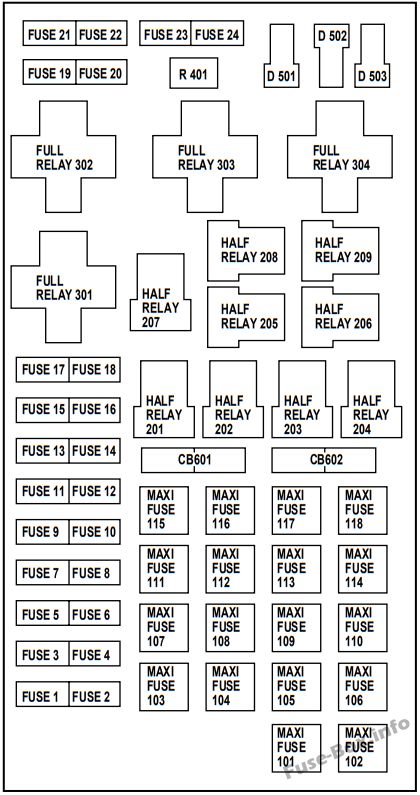
Assignment of the fuses in the Power distribution box (2000)
| № | Amp Rating | Power Distribution Box Description |
|---|---|---|
| 1 | 20A * | Power Point |
| 2 | 30A* | Powertrain Control Module |
| 3 | 30A* | Headlamps/Autolamps |
| 4 | 20A* | Console Powerpoint |
| 5 | 20A* | Trailer Tow Backup/Park Lamps |
| 6 | 15 A* | Parklamps/Autolamps, Feeds Passenger Compartment Fuse 18 |
| 7 | 20A* | Horn |
| 8 | 30A* | Power Door Locks |
| 9 | 15 A* | Daytime Running Lamps (DRL), Fog Lamps |
| 10 | 20A* | Fuel Pump |
| 11 | 20A* | Alternator Field |
| 12 | 10 A* | Rear Wipers |
| 13 | 15 A* | A/C Clutch |
| 14 | — | Not Used |
| 15 | 10 A* | Running Board Lamps |
| 16 | — | Not Used |
| 17 | 10 A* | Flip Windows |
| 18 | 15 A* | Powertrain Control Module, Fuel Injectors, Fuel Pump, Mass Air Flow Sensor |
| 19 | 10 A* | Trailer Tow Stop and Right Turn Lamp |
| 20 | 10 A* | Trailer Tow Stop and Left Turn Lamp |
| 21 | — | Not Used |
| 22 | — | Not Used |
| 23 | 15 A* | HEGO Sensors, Canister Vent, Automatic Transmission, CMS Sensor |
| 24 | — | Not Used |
| 101 | 30A** | Trailer Tow Battery Charge |
| 102 | 50A** | Four Wheel Antilock Brake Module |
| 103 | 50A** | Junction Block Battery Feed |
| 104 | 30A** | 4×4 Shift Motor & Clutch |
| 105 | 40A** | Climate Control Front Blower |
| 106 | — | Not Used |
| 107 | — | Not Used |
| 108 | 30A** | Trailer Tow Electric Brake |
| 109 | 50A** | Air Suspension Compressor |
| 110 | 30A** | Heated Seats |
| 111 | 40A** | Ignition Switch Battery Feed (Run/Start Circuit) |
| 112 | 30A** | Drivers Power Seat, Adjustable Pedals, Memory Module |
| 113 | 40A** | Ignition Switch Battery Feed (Run and Accessory Circuits) |
| 114 | 30A** | Climate Control Auxiliary Blower |
| 115 | — | Not Used |
| 116 | 40A** | Rear Window Defroster, Heated Mirrors |
| 117 | — | Not Used |
| 118 | — | Not Used |
| 201 | — | Trailer Tow Park Lamp Relay |
| 202 | — | Front Wiper Run/Park Relay |
| 203 | — | Trailer Tow Backup Lamp Relay |
| 204 | — | A/C Clutch Relay |
| 205 | — | Rear Wiper Down |
| 206 | — | Foglamp Relay |
| 207 | — | Front Washer Pump Relay |
| 208 | — | Rear Washer Pump Relay |
| 209 | — | Rear Wiper Up |
| 301 | — | Fuel Pump Relay |
| 302 | — | Trailer Tow Battery Charge Relay |
| 303 | — | Wiper Hi/Lo Relay |
| 304 | — | Powertrain Control Module Relay |
| 401 | — | Not Used |
| 501 | — | Powertrain Control Module Diode |
| 502 | — | A/C Clutch Diode |
| 503 | — | Not Used |
| 601 | 30A | Delayed Accessory (Power Windows, Flip Windows, Moonroof) |
| 602 | — | Not Used |
| * Mini fuses ** Maxi fuses |
2001, 2002
Passenger compartment
Assignment of the fuses in the Passenger compartment (2001, 2002)
| № | Amp Rating | Passenger Compartment Fuse Panel Description |
|---|---|---|
| 1 | 25A | Audio |
| 2 | 5A | Overhead Trip Computer, Electronic Automatic Temperature Control (EATC), Powertrain Control Module (PCM), Cluster |
| 3 | 20A | Cigar Lighter, OBD-II Scan Tool Connector |
| 4 | 7.5A | Remote Entry Module, Mirrors, Memory Functions (Seats and Pedals) |
| 5 | 15A | Speed Control Module, Reverse Lamp, EVO Module, Climate Mode Switch (Front Blower Relay), Daytime Running Lamp Relay, Reverse Sensing System, Autolock, E/C Mirror |
| 6 | 5A | Cluster, Overhead Trip Computer, Compass, Brake Shift Interlock Solenoid, Air Suspension Module, GEM Module, EVO Steering Sensor, Heated Mirror, Rear Defroster, Reverse Sensing System |
| 7 | 5A | Aux A/C Blower Relay (via fuse 22) |
| 8 | 5A | Radio, Remote Entry Module, GEM Module |
| 9 | — | Not Used |
| 10 | — | Not Used |
| 11 | 30A | Front Washer Pump Relay, Wiper Run/Park Relay, Wiper Hi/LO Relay, Windshield Wiper Motor, Rear Washer Pump Relay |
| 12 | 15A | Air Suspension Switch |
| 13 | 20A | Stop Lamp Switch (Lamps), Turn/Hazard Flasher, Speed Control Module |
| 14 | 15A | Rear Wipers, Running Board Lamps, Battery Saver Relay, Interior Lamp Relay, Accessory Delay Relay (Power Windows, Moonroof, Flip Windows) |
| 15 | 5A | Stop Lamp Switch, (Speed Control, Brake Shift Interlock, ABS, PCM Module Inputs, Air Suspension Module, Autolock), GEM Module |
| 16 | 20A | Headlamps (Hi Beams), Cluster (Hi Beam Indicator) |
| 17 | 10A | Heated Mirrors, Heated Grid Switch Indicator |
| 18 | 5A | Instrument Illumination (Dimmer Switch Power) |
| 19 | — | Not Used |
| 20 | 5A | Audio, Air Suspension Module, GEM Module, Memory Module |
| 21 | 15A | Starter Relay, Fuse 20, Transmission Range Switch |
| 22 | 10A | Air Bag Module, Intelligent Passenger Airbag Deactivation Module |
| 23 | 10A | Aux A/C, Heated Seats, Trailer Tow Battery Charge, Turn/Hazard Flasher, 4×4 Clutch Relay, Overhead Console, E/C Mirror, 4 Wheel Anti-Lock Brake System (4WABS) Module |
| 24 | 10A | EATC Module, EATC Blower Relay, Climate Control Switch Assembly, Feeds Fuse 7 |
| 25 | — | Not Used |
| 26 | 10A | Right Side Low Beam Headlamp |
| 27 | 5A | Foglamp Relay and Foglamp Indicator |
| 28 | 10A | Left Side Low Beam Headlamp |
| 29 | 5A | Autolamp Module, Transmission Overdrive Control Switch |
| 30 | 30A | Passive Anti Theft Transceiver, Cluster, Ignition Coils, Powertrain Control Module Relay |
| 31 | 10A | Rear Integrated Control Panel (Audio), CD Player |
| Relay 1 | — | Interior Lamp Relay |
| Relay 2 | — | Battery Saver Relay |
| Relay 3 | — | Rear Window Defroster Relay |
| Relay 4 | — | One Touch Down Window Relay |
| Relay 5 | — | ACC Delay Relay |
Engine compartment
Assignment of the fuses in the Power distribution box (2001, 2002)
| № | Amp Rating | Power Distribution Box Description |
|---|---|---|
| 1 | 20A * | Power Point |
| 2 | 30A* | Powertrain Control Module |
| 3 | 30A* | Headlamps/Autolamps |
| 4 | 20A* | Console PowerPoint |
| 5 | 20A* | Trailer Tow Backup/Park Lamps |
| 6 | 15 A* | Parklamps/Autolamps, Feeds Passenger Compartment Fuse 18 |
| 7 | 20A* | Horn |
| 8 | 30A* | Power Door Locks |
| 9 | 15 A* | Daytime Running Lamps (DRL), Fog Lamps |
| 10 | 20A* | Fuel Pump |
| 11 | 20A* | Alternator Field |
| 12 | 10 A* | Rear Wipers |
| 13 | 15 A* | A/C Clutch |
| 14 | — | Not Used |
| 15 | 10 A* | Running Board Lamps |
| 16 | — | Not Used |
| 17 | 10 A* | Flip Windows |
| 18 | 15 A* | Powertrain Control Module, Fuel Injectors, Fuel Pump, Mass Air Flow Sensor |
| 19 | 10 A* | Trailer Tow Stop and Right Turn Lamp |
| 20 | 10 A* | Trailer Tow Stop and Left Turn Lamp |
| 21 | — | Not Used |
| 22 | — | Not Used |
| 23 | 15 A* | HEGO Sensors, Canister Vent, Automatic Transmission, CMS Sensor |
| 24 | — | Not Used |
| 101 | 30A** | Trailer Tow Battery Charge |
| 102 | 50A** | Four Wheel Antilock Brake Module |
| 103 | 50A** | Junction Block Battery Feed |
| 104 | 30A** | 4×4 Shift Motor & Clutch |
| 105 | 40A** | Climate Control Front Blower |
| 106 | — | Not Used |
| 107 | — | Not Used |
| 108 | 30A** | Trailer Tow Electric Brake |
| 109 | 50A** | Air Suspension Compressor |
| 110 | 30A** | Heated Seats |
| 111 | 40A** | Ignition Switch Battery Feed (Run/Start Circuit) |
| 112 | 30A** | Drivers Power Seat, Adjustable Pedals, Memory Module |
| 113 | 40A** | Ignition Switch Battery Feed (Run and Accessory Circuits) |
| 114 | 30A** | Climate Control Auxiliary Blower |
| 115 | — | Not Used |
| 116 | 40A** | Rear Window Defroster, Heated Mirrors |
| 117 | — | Not Used |
| 118 | — | Not Used |
| 201 | — | Trailer Tow Park Lamp Relay |
| 202 | — | Front Wiper Run/Park Relay |
| 203 | — | Trailer Tow Backup Lamp Relay |
| 204 | — | A/C Clutch Relay |
| 205 | — | Rear Wiper Down |
| 206 | — | Foglamp Relay |
| 207 | — | Front Washer Pump Relay |
| 208 | — | Rear Washer Pump Relay |
| 209 | — | Rear Wiper Up |
| 301 | — | Fuel Pump Relay |
| 302 | — | Trailer Tow Battery Charge Relay |
| 303 | — | Wiper Hi/Lo Relay |
| 304 | — | Powertrain Control Module Relay |
| 401 | — | Not Used |
| 501 | — | Powertrain Control Module Diode |
| 502 | — | A/C Clutch Diode |
| 503 | — | Not Used |
| 601 | 30A | Delayed Accessory (Power Windows, Flip Windows, Moonroof) |
| 602 | — | Not Used |
| * Mini fuses ** Maxi fuses |


