


Fuse Layout Ford Expedition 2007-2014
Contents

Cigar lighter (power outlet) fuses in the Ford Expedition are the fuses №10 (Rear console power point), №41 (IP/Console power point), №51 (Cargo power point) and №52 (Cigarette lighter) in the Engine compartment fuse box (2007-2008). Since 2009 – fuses №65 (Auxiliary power point (instrument panel)), №66 (Auxiliary power point (rear of center console)), №71 (Auxiliary power point/cigar lighter) and №72 (Auxiliary power point (right rear quarter panel)) in the Engine compartment fuse box.
Table of Contents
Fuse box location
Passenger compartment
The fuse panel is located under the right-hand side of the instrument panel behind the cover.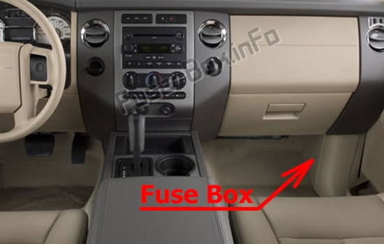
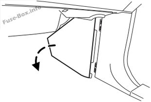
To remove the trim panel for access to the fuse box, pull the panel toward you and swing it out away from the side and remove it.
To reinstall it, line up the tabs with the grooves on the panel, then push it shut.
To remove the fuse box cover, press in the tabs on both sides of the cover, then pull the cover off.
To reinstall the fuse box cover, place the top part of the cover on the fuse panel, then push the bottom part of the cover until you hear it click shut. Gently pull on the cover to make sure it is seated properly.
Engine compartment
The power distribution box is located in the engine compartment.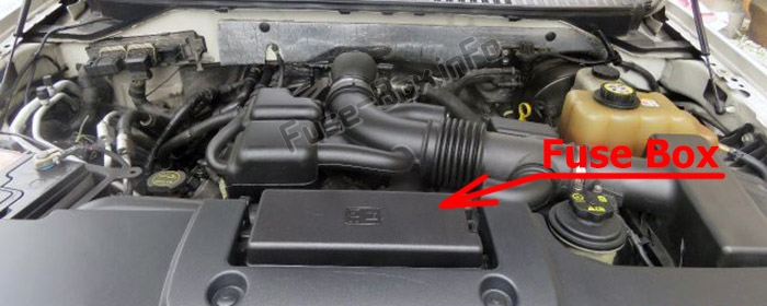
Fuse box diagrams
2007, 2008
Passenger compartment
Assignment of the fuses in the Passenger compartment (2007, 2008)
| № | Amp Rating | Description |
|---|---|---|
| 1 | 30A | Smart window #1 |
| 2 | 15A | Driver side module, CHMSL brake on/off |
| 3 | 15A | FES |
| 4 | 30A | Smart window #2 |
| 5 | 10A | Keypad illumination, 3rd row’ seat enable, Brake Shift Interlock (BSI), SPDJB, TPMS initiators |
| 6 | 20A | Turn signals |
| 7 | 10A | Low beam headlamps (left) |
| 8 | 10A | Low beam headlamps (right) |
| 9 | 15A | Interior lights |
| 10 | 15A | Backlighting, Cargo lamps, Puddle lamps |
| 11 | 10A | 4×4 |
| 12 | 7.5A | Power mirror switch, Driver side power seat memory, Driver side power fold mirror relay motor |
| 13 | 7.5A | Power fold mirror motor, Digital Signal Processing (DSP) |
| 14 | 10A | Power liftgate module – keep-alive power |
| 15 | 10A | Climate control |
| 16 | 15A | Electronic parking brake release |
| 17 | 20A | All lock motor feeds, Liftgate release, Liftglass release |
| 18 | 20A | Not used (Spare) |
| 19 | 25A | Rear wiper |
| 20 | 15A | Adjustable pedals, Datalink |
| 21 | 15A | Fog lamps |
| 22 | 15A | Park lamps relay |
| 23 | 15A | High beam headlamps |
| 24 | 20A | Horn relay |
| 25 | 10A | Demand lamps |
| 26 | 10A | Instrument panel cluster |
| 27 | 20A | Ignition switch |
| 28 | 5A | Radio |
| 29 | 5A | Instrument panel cluster |
| 30 | 5A | Not used (Spare) |
| 31 | 10A | Compass, Automatic dimming rear view mirror |
| 32 | 10A | Restraints control module |
| 33 | 10A | Ebrake |
| 34 | 5A | Not used (spare) |
| 35 | 10A | Rear park assist, 4×4 |
| 36 | 5A | PATS transceiver |
| 37 | 10A | Climate control |
| 38 | 20A | Subwoofer/Amp (Audiophile radio) |
| 39 | 20A | Radio |
| 40 | 20A | Instrument panel amp, DSP, Radio, 4×4 module |
| 41 | 15A | Radio, Fixed backlighting |
| 42 | 10A | Upfitter relay coil, Trailer tow, Battery charge coil |
| 43 | 10A | Rear wiper logic |
| 44 | 10A | Customer access feed |
| 45 | 5A | Front wiper logic |
| 46 | 7.5A | Not used (Spare) |
| 47 | 30A Circuit Breaker | Power windows, Moon roof |
| 48 | — | Delayed accessoiy relay |
Engine compartment
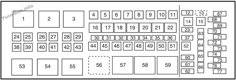
Assignment of the fuses in the Power distribution box (2007, 2008)
| № | Amp Rating | Description |
|---|---|---|
| 1 | — | Blower relay |
| 2 | — | Not used |
| 3 | — | Rear window defroster relay |
| 4 | 30A** | Third row seats (driver side) |
| 5 | 40A** | Trailer tow connector (electric brake) |
| 6 | 60A** | ABS (valves) |
| 7 | — | Not used |
| 8 | 40A** | Heated/cooled seats |
| 9 | 60A** | ABS (pump) |
| 10 | 20A** | Rear console power point |
| 11 | 30A** | Auxiliary blower |
| 12 | 25A* | Trailer tow connector (park lamps) |
| 13 | 30A * | Trailer tow connector (battery charge) |
| 14 | — | Not used |
| 15 | — | Not used |
| 16 | — | A/C clutch relay |
| 17 | — | Not used |
| 18 | — | Fuel pump relay |
| 19 | — | Back-up relay |
| 20 | — | Trailer tow connector relay (left turn signal) |
| 21 | — | Trailer tow connector relay (right turn signal) |
| 22 | — | Not used |
| 23 | 15 A* | Heated mirrors |
| 24 | 40A** | Blower motor |
| 25 | — | Not used |
| 26 | — | Not used |
| 27 | 30A** | Power liftgate |
| 28 | 40A** | Rear window defroster, Heated mirror |
| 29 | 30A** | Passenger seat |
| 30 | 10 A* | A/C clutch |
| 31 | 15 A* | Brake lamps |
| 32 | 20 A* | Fuel pump |
| 33 | 20 A* | Back-up lamps |
| 34 | 25A* | Trailer tow connector (stop/turn lamps) |
| 35 | 20 A* | 4×4 module |
| 36 | 10 A* | Powertrain Control Module (PCM) – Keep alive power, Canister vent |
| 37 | 15 A* | Transmission B+ |
| 38 | 30A** | Third row seats (passenger side) |
| 39 | 50A** | Air suspension pump |
| 40 | 30A** | Starter motor |
| 41 | 20A** | IP/Console power point |
| 42 | — | Not used |
| 43 | 20A** | 4×4 module motor |
| 44 | — | Not used |
| 45 | 30A** | Driver seat |
| 46 | 40A** | Run/Start bus bar |
| 47 | 30A** | Air suspension – solenoids |
| 48 | — | Not used |
| 49 | 30A** | Front wipers/washer |
| 50 | 30A** | PCM – bus bar |
| 51 | 20A** | Cargo power point |
| 52 | 20A** | Cigarette lighter |
| 53 | — | Air suspension relay |
| 54 | — | Starter relay |
| 55 | — | Trailer tow connector relay (park lamp) |
| 56 | — | Trailer tow connector relay (battery charge) |
| 57 | — | Run/Start relay |
| 58 | — | Not used |
| 59 | — | PCM relay |
| 60 | — | Not used |
| 61 | A/C clutch diode | |
| 62 | — | Fuel pump diode |
| 63 | 15 A* | Trailer tow connector (back-up lamp) |
| 64 | — | Not used |
| 65 | 10 A* | Air suspension logic |
| 66 | — | Not used |
| 67 | 10 A* | Blower coil |
| 68 | — | Not used |
| 69 | 30A* | Run/Start – passenger compartment fuse panel |
| 70 | 20 A* | PCM (sensors) – EFC, A/C clutch coil |
| 71 | 5A* | Fuel coil, ISP-R |
| 72 | 20 A* | PCM (ignition coils) |
| 73 | 5A* | Transmission ignition |
| 74 | 20 A* | PCM (sensors) – HEGO/CMS, MAFS, EVMV, CMCV, Speed deactivation switch, VCT |
| 75 | 5A* | 4×4 Integrated Wheel Ends (IWE) solenoid |
| 76 | 20 A* | PCM – VPWR |
| 77 | 10 A* | ABS logic, Heated PCV |
| * Mini Fuses ** Cartridge Fuses |
2009
Passenger compartment
Assignment of the fuses in the Passenger compartment (2009)
| № | Amp Rating | Protected Circuits |
|---|---|---|
| 1 | 30A | Smart window #1 |
| 2 | 15A | Driver side memory module |
| 3 | 15A | FES, Audio rear seat controls, SDARS, SYNC |
| 4 | 30A | Smart window #2 |
| 5 | 10A | Keypad illumination, 3rd row’ seat enable, Brake Shift Interlock (BSI), SPDJB |
| 6 | 20A | Turn signals |
| 7 | 10A | Low beam headlamps (left) |
| 8 | 10A | Low beam headlamps (right) |
| 9 | 15A | Interior lights |
| 10 | 15A | Backlighting, Puddle lamps |
| 11 | 10A | Not used (spare) |
| 12 | 7.5A | Power mirror switch, Driver seat memory switch |
| 13 | 5A | Not used (Spare) |
| 14 | 10A | Power liftgate module – keep-alive power |
| 15 | 10A | Climate control |
| 16 | 15A | Not used (Spare) |
| 17 | 20A | All lock motor feeds, Liftgate release, Liftglass release |
| 18 | 20A | Second row heated seats |
| 19 | 25A | Rear wiper |
| 20 | 15A | Adjustable pedals, Datalink |
| 21 | 15A | Fog lamps, Cornering lamps |
| 22 | 15A | Park lamps relay |
| 23 | 15A | High beam headlamps |
| 24 | 20A | Horn relay |
| 25 | 10A | Demand lamps, Glovebox, Visor |
| 26 | 10A | Instrument panel cluster |
| 27 | 20A | Ignition switch |
| 28 | 5A | Radio |
| 29 | 5A | Instrument panel cluster |
| 30 | 5A | Not used (Spare) |
| 31 | 10A | Not used (Spare) |
| 32 | 10A | Restraints control module |
| 33 | 10A | Not used (Spare) |
| 34 | 5A | Not used (Spare) |
| 35 | 10A | Rear park assist, 4×4, rear video camera |
| 36 | 5A | PATS transceiver |
| 37 | 10A | Climate control |
| 38 | 20A | Subwoofer/Amp (Audiophile radio) |
| 39 | 20A | Radio |
| 40 | 20A | Navigation system amplifier |
| 41 | 15A | Power windows, Power vents, Power moon roof, Auto dimming rear view’ mirror |
| 42 | 10A | Not used (Spare) |
| 43 | 10A | Rear wiper logic, Rain sensor |
| 44 | 10A | Trailer tow battery charge relay coil |
| 45 | 5A | Front wiper logic |
| 46 | 7.5A | Climate control, Auxiliary relay control |
| 47 | 30A Circuit Breaker | Power windows, Moon roof |
| 48 | — | Delayed accessoiy relay |
Engine compartment
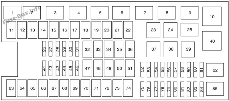
Assignment of the fuses in the Power distribution box (2009)
| № | Amp Rating | Protected Circuits |
|---|---|---|
| 1 | — | PCM power relay |
| 2 | — | Starter relay |
| 3 | — | Not used |
| 4 | — | Trailer tow relay |
| 5 | — | Fuel pump relay |
| 6 | — | Trailer tow park lamp relay |
| 7 | — | Heated backlite/Mirror relay |
| 8 | — | Not used |
| 9 | — | Run/Start relay |
| 10 | — | Rear air suspension (RAS) relay |
| 11 | 40A** | Power running board motors |
| 12 | 40A** | Run/Start relay |
| 13 | 30A ** | Starter relay |
| 14 | — | Not used |
| 15 | — | Not used |
| 16 | 20A** | Not used |
| 17 | — | Not used |
| 18 | 30A** | Trailer brake |
| 19 | 60A** | Rear air suspension relay feed |
| 20 | 20A** | 4×4 module |
| 21 | 30A** | Trailer tow battery charge |
| 22 | 30A** | Passenger power seat |
| 23 | — | A/C clutch relay |
| 24 | — | Not used |
| 25 | — | Not used |
| 26 | 15 A* | TCM power |
| 27 | 20 A* | 4×4 HAT1 |
| 28 | 25A* | Trailer tow park lamp relay feed |
| 29 | 20 A* | Back up lamps, IWD solenoid |
| 30 | 10 A* | A/C clutch |
| 31 | — | Not used |
| 32 | 40A** | Blower motor relay feed |
| 33 | — | Not used |
| 34 | 30A** | Auxiliary blower motor |
| 35 | 30A** | PCM relay |
| 36 | 30A** | Power liftgate |
| 37 | — | Trailer tow left hand stop/turn relay |
| 38 | — | Trailer tow right hand stop/turn relay |
| 39 | — | Back up lamps |
| 40 | — | Blower motor relay |
| 41 | 10 A* | TCM PCM KAPWR |
| 42 | — | Not used |
| 43 | 15 A* | Brake on/off switch |
| 44 | 20 A* | Fuel pump relay |
| 45 | 25A* | Trailer tow stop turn relay feed |
| 46 | — | Not used |
| 47 | — | Not used |
| 48 | 30A** | Rear air suspension module |
| 49 | — | Not used |
| 50 | 30A** | Front wiper motor |
| 51 | 40A** | Heated backlite/mirror relay |
| 52 | 10 A* | ABS R/S feed |
| 53 | 10 A* | Rear air suspension module R/S feed |
| 54 | 5A* | TCM R/S power |
| 55 | 5A* | Fuel pump relay R/S feed |
| 56 | 30A* | SPJB R/S feed |
| 57 | 10 A* | Blower motor R/S feed |
| 58 | 15 A* | Trailer tow backup lamps |
| 59 | 15 A* | Heated mirrors |
| 60 | — | One-touch Start diode |
| 61 | — | Fuel pump diode |
| 62 | — | Not used |
| 63 | — | Not used |
| 64 | 30A** | Moon roof |
| 65 | 20A** | Auxiliary power point |
| 66 | 20A** | Auxiliary power point |
| 67 | 40A** | Climate controlled seats |
| 68 | 60A** | ABS valves |
| 69 | 60A** | ABS pump |
| 70 | 40A** | Left-hand and right-hand third row power fold seat |
| 71 | 20A** | Auxiliary power point |
| 72 | 20A** | Auxiliary power point |
| 73 | — | Not used |
| 74 | 30A** | Driver power seat/DSM |
| 75 | 20 A* | PCM – VPWR1 |
| 76 | 20 A* | PCM – VPWR2 |
| 77 | 15 A* | VPWR4, Ignition coils |
| 78 | — | Not used |
| 79 | 20 A* | PCM – VPWR3 |
| 80 | — | Not used |
| 81 | — | Not used |
| 82 | — | Not used |
| 83 | — | Not used |
| 84 | — | Not used |
| 85 | — | Wiper motor relay |
| * Mini Fuses ** Cartridge Fuses |
2010
Passenger compartment
Assignment of the fuses in the Passenger compartment (2010)
| № | Amp Rating | Protected Circuits |
|---|---|---|
| 1 | 30A | Smart window #1 |
| 2 | 15A | Driver side memory module |
| 3 | 15A | Family entertainment system, Audio rear seat controls, Satellite radio, SYNC® |
| 4 | 30A | Smart window #2 |
| 5 | 10A | Keypad illumination, 3rd row seat enable, Brake shift interlock (BSI), Passenger compartment fuse panel |
| 6 | 20A | Turn signals |
| 7 | 10A | Low beam headlamps (left) |
| 8 | 10A | Low beam headlamps (right) |
| 9 | 15A | Interior lights |
| 10 | 15A | Switch backlighting, Puddle lamps |
| 11 | 10A | Not used (spare) |
| 12 | 7.5A | Power mirrors, Driver seat memory switch |
| 13 | 5A | Not used (spare) |
| 14 | 10A | Power liftgate module – keep-alive power |
| 15 | 10A | Climate control, Global positioning satellite module |
| 16 | 15A | Not used (spare) |
| 17 | 20A | Door locks, Liftgate release, Liftglass release |
| 18 | 20A | Second row heated seats |
| 19 | 25A | Rear wiper |
| 20 | 15A | Adjustable pedals, Datalink |
| 21 | 15A | Fog lamps |
| 22 | 15A | Park lamps |
| 23 | 15A | High beam headlamps |
| 24 | 20A | Horn |
| 25 | 10A | Demand lamps, Glovebox, Visor |
| 26 | 10A | Instrument panel cluster |
| 27 | 20A | Ignition switch |
| 28 | 5A | Radio |
| 29 | 5A | Instrument panel cluster |
| 30 | 5A | Not used (spare) |
| 31 | 10A | Not used (spare) |
| 32 | 10A | Airbag module |
| 33 | 10A | Not used (spare) |
| 34 | 5A | Not used (spare) |
| 35 | 10A | Rear park assist, 4×4, rear video camera |
| 36 | 5A | Passive anti-theft system |
| 37 | 10A | Climate control |
| 38 | 20A | Subwoofer |
| 39 | 20A | Radio |
| 40 | 20A | Navigation system |
| 41 | 15A | Power windows, Power vents, Power moon roof, Auto dimming rear view’ mirror |
| 42 | 10A | Not used (spare) |
| 43 | 10A | Rear wiper logic, Rain sensor |
| 44 | 10A | Trailer tow battery charge relay coil |
| 45 | 5A | Front wiper logic |
| 46 | 7.5A | Climate control, Auxiliary relay control |
| 47 | 30A Circuit Breaker | Power window’s, Moon roof |
| 48 | — | Delayed accessory relay |
Engine compartment
Assignment of the fuses in the Power distribution box (2010)
| № | Amp Rating | Protected Circuits |
|---|---|---|
| 1 | — | Powertrain control module (PCM) relay |
| 2 | — | Starter relay |
| 3 | — | Electronic fan 2 relay |
| 4 | — | Trailer tow battery charge relay |
| 5 | — | Fuel pump relay |
| 6 | — | Electronic fan 1 relay |
| 7 | — | Rear window defroster/heated mirror relay |
| 8 | — | Electronic fan 3 relay |
| 9 | — | Run/Start (R/S) relay |
| 10 | — | Rear air suspension (RAS) relay |
| 11 | 40A** | Power running board |
| 12 | 40A** | R/S relay |
| 13 | 30A ** | Starter relay |
| 14 | 40A** | Electronic fan |
| 15 | — | Not used |
| 16 | 40A** | Electronic fan |
| 17 | — | Not used |
| 18 | 30A** | Trailer brake |
| 19 | 60A** | RAS relay feed |
| 20 | 20A** | 4×4 module |
| 21 | 30A** | Trailer tow battery charge |
| 22 | 30A** | Passenger power seat |
| 23 | — | A/C clutch relay |
| 24 | — | Trailer tow park lamp relay |
| 25 | — | Not used |
| 26 | 15A* | Transmission control module (TCM) keep-alive power |
| 27 | 20 A* | 4×4 |
| 28 | 2 5 A* | Trailer tow park lamp relay |
| 29 | 20 A* | Backup lamps, Integrated wheel end solenoid |
| 30 | 10A* | A/C clutch relay |
| 31 | — | Not used |
| 32 | 40A** | Blower motor relay |
| 33 | — | Not used |
| 34 | 30A** | Auxiliary blower motor |
| 35 | 30A** | PCM relay |
| 36 | 30A** | Power liftgate |
| 37 | — | Trailer tow left hand stop/turn relay |
| 38 | — | Trailer tow right hand stop/turn relay |
| 39 | — | Backup lamps relay |
| 40 | — | Blower motor relay |
| 41 | 10 A* | PCM keep-alive power |
| 42 | — | Not used |
| 43 | 5A* | Brake on/off switch |
| 44 | 20 A* | Fuel pump relay |
| 45 | 25A* | Trailer tow stop/turn lamps relay |
| 46 | — | Not used |
| 47 | — | Not used |
| 48 | 30A** | RAS module |
| 49 | — | Not used |
| 50 | 30A** | Front wiper motor |
| 51 | 40A** | Rear window defroster/heated mirror relay |
| 52 | 10 A* | Anti-lock brake system (ABS) R/S feed |
| 53 | 10 A* | RAS module |
| 54 | 5A* | TCM R/S feed |
| 55 | 5A* | Fuel pump relay coil R/S feed |
| 56 | 30A* | Passenger compartment fuse panel R/S feed |
| 57 | 10 A* | Blower motor R/S feed |
| 58 | 15 A* | Trailer tow backup lamps |
| 59 | 15A* | Heated mirrors |
| 60 | — | One-touch start diode |
| 61 | — | Fuel pump diode |
| 62 | — | Not used |
| 63 | 25A** | Electronic fan |
| 64 | 30A** | Moon roof |
| 65 | 20A** | Auxiliary power point 2 |
| 66 | 20A** | Auxiliary power point 3 |
| 67 | 40A** | Climate controlled seats |
| 68 | 60A** | ABS valves |
| 69 | 60A** | ABS pump |
| 70 | 40A** | Third row power fold seat |
| 71 | 20A** | Auxiliary power point/cigar lighter |
| 72 | 20A** | Auxiliary power point 4 |
| 73 | — | Not used |
| 74 | 30A** | Driver power seat |
| 75 | 20 A* | Vehicle power 1 – PCM |
| 76 | 20 A* | Vehicle power 2 – PCM |
| 77 | 15A* | Vehicle power 4 – ignition coils |
| 78 | — | Not used |
| 79 | 20 A* | Vehicle power 3 – PCM |
| 80 | — | Not used |
| 81 | — | Not used |
| 82 | — | Not used |
| 83 | — | Not used |
| 84 | — | Not used |
| 85 | — | Wiper motor relay |
| * Mini Fuses ** Cartridge Fuses |
2011, 2012
Passenger compartment
Assignment of the fuses in the Passenger compartment (2011, 2012)
| № | Amp Rating | Protected Circuits |
|---|---|---|
| 1 | 30A | Driver window |
| 2 | 15A | Driver side memory module |
| 3 | 15A | Audio rear seat controls, Satellite radio, SYNC® |
| 4 | 30A | Not used (spare) |
| 5 | 10A | Keypad illumination, 3rd row seat enable, Brake shift interlock (BSI), Smart fuse panel logic power |
| 6 | 20A | Turn signals |
| 7 | 10A | Low’ beam headlamps (left) |
| 8 | 10A | Low’ beam headlamps (right) |
| 9 | 15A | Interior lights |
| 10 | 15A | Switch backlighting, Puddle lamps |
| 11 | 10A | Not used (spare) |
| 12 | 7.5A | Power mirrors, Driver seat memory switch |
| 13 | 5A | Not used (spare) |
| 14 | 10A | Power liftgate module – keep-alive power |
| 15 | 10A | Climate control, Global positioning satellite module |
| 16 | 15A | Not used (spare) |
| 17 | 20A | Door locks, Liftgate release, Liftglass release |
| 18 | 20A | Second row heated seats |
| 19 | 25A | Rear wiper |
| 20 | 15A | Adjustable pedals, Datalink |
| 21 | 15A | Fog lamps |
| 22 | 15A | Park lamps |
| 23 | 15A | High beam headlamps |
| 24 | 20A | Horn |
| 25 | 10A | Demand lamps, Glovebox, Visor |
| 26 | 10A | Instrument panel cluster |
| 27 | 20A | Ignition switch |
| 28 | 5A | Radio |
| 29 | 5A | Instrument panel cluster |
| 30 | 5A | Not used (spare) |
| 31 | 10A | Not used (spare) |
| 32 | 10A | Airbag module |
| 33 | 10A | Not used (spare) |
| 34 | 5A | Not used (spare) |
| 35 | 10A | Rear park assist, 4×4, rear video camera, 2nd row heated seats |
| 36 | 5A | Passive anti-theft system |
| 37 | 10A | Climate control |
| 38 | 20A | Subwoofer |
| 39 | 20A | Radio |
| 40 | 20A | Navigation amplifier |
| 41 | 15A | Power windows, Power vents, Power moon roof, Auto dimming rear view mirror, 110V AC power point |
| 42 | 10A | Not used (spare) |
| 43 | 10A | Rear wiper logic, Rain sensor |
| 44 | 10A | Trailer tow battery charge relay coil |
| 45 | 5A | Front wiper logic |
| 46 | 7.5A | Climate control, Auxiliary relay control |
| 47 | 30A Circuit Breaker | Power windows, Moon roof |
| 48 | — | Delayed accessory relay |
Engine compartment
Assignment of the fuses in the Power distribution box (2011, 2012).xl
| № | Amp Rating | Protected Circuits |
|---|---|---|
| 1 | — | Powertrain control module (PCM) relay |
| 2 | — | Starter relay |
| 3 | — | Blower motor relay |
| 4 | — | Trailer tow (TT) battery charge relay |
| 5 | — | Fuel pump relay |
| 6 | — | Electronic fan 1 relay |
| 7 | — | Rear window defroster/heated mirror relay |
| 8 | — | Electronic fan 3 relay |
| 9 | — | Run/Start (R/S) relay |
| 10 | — | Rear air suspension (RAS) relay |
| 11 | 40A** | Power running board |
| 12 | 40A** | R/S relay |
| 13 | 30A ** | Starter relay |
| 14 | 40A** | Electronic fan |
| 15 | — | Not used |
| 16 | 40A** | Electronic fan |
| 17 | — | Not used |
| 18 | 30A** | Trailer brake |
| 19 | 60A** | RAS relay feed |
| 20 | 20A** | 4×4 module |
| 21 | 30A** | TT battery charge relay |
| 22 | 30A** | Passenger power seat |
| 23 | — | A/C clutch relay |
| 24 | — | TT park lamp relay |
| 25 | — | Not used |
| 26 | 15 A* | Transmission control module (TCM) keep-alive power |
| 27 | 20 A* | 4×4 |
| 28 | 25A* | Trailer tow park lamp relay |
| 29 | 20 A* | Backup lamps, Integrated wheel end solenoid |
| 30 | 10 A* | A/C clutch relay |
| 31 | — | Not used |
| 32 | 40A** | Blower motor relay |
| 33 | 40A** | 110V AC power point |
| 34 | 30A** | Auxiliary blower motor |
| 35 | 30A** | PCM relay |
| 36 | 30A** | Power liftgate |
| 37 | — | TT left hand stop/turn relay |
| 38 | — | TT right hand stop/turn relay |
| 39 | — | Backup lamps relay |
| 40 | — | Electronic fan 2 relay |
| 41 | 10A* | PCM keep-alive power |
| 42 | — | Not used |
| 43 | 5A* | Brake on/off switch |
| 44 | 20 A* | Fuel pump relay |
| 45 | 25 A* | TT stop/turn lamps relay |
| 46 | — | Not used |
| 47 | — | Not used |
| 48 | 30A** | RAS module |
| 49 | — | Not used |
| 50 | 30A** | Front wiper motor relay |
| 51 | 40A** | Rear window defroster/heated mirror relay |
| 52 | 10A* | Anti-lock brake system (ABS) R/S feed |
| 53 | 10A* | RAS module |
| 54 | 5A* | TCM R/S feed |
| 55 | 5A* | Fuel pump relay coil R/S feed |
| 56 | 30 A* | Passenger compartment fuse panel R/S feed |
| 57 | 10A* | Blower motor relay coil |
| 58 | 15A* | TT backup lamps |
| 59 | 15A* | Heated mirrors |
| 60 | — | One-touch start diode |
| 61 | — | Fuel pump diode |
| 62 | — | Not used |
| 63 | 25A** | Electronic fan |
| 64 | 30A** | Moon roof |
| 65 | 20A** | Auxiliary power point (instrument panel) |
| 66 | 20A** | Auxiliary power point (rear of center console) |
| 67 | 40A** | Front row climate controlled seats |
| 68 | 60A** | ABS valves |
| 69 | 60A** | ABS pump |
| 70 | 40A** | Third row power fold seat |
| 71 | 20A** | Auxiliary power point/cigar lighter |
| 72 | 20A** | Auxiliary power point (right rear quarter panel) |
| 73 | — | Not used |
| 74 | 30A** | Driver power seat |
| 75 | 20A* | Vehicle power 1 – PCM |
| 76 | 20 A* | Vehicle power 2 – PCM |
| 77 | 15 A* | Vehicle power 4 – ignition coils |
| 78 | — | Not used |
| 79 | 20 A* | Vehicle power 3 – PCM |
| 80 | — | Not used |
| 81 | — | Not used |
| 82 | — | Not used |
| 83 | — | Not used |
| 84 | — | Not used |
| 85 | — | Wiper motor relay |
| * Mini Fuses ** Cartridge Fuses |
2013, 2014
Passenger compartment
Assignment of the fuses in the Passenger compartment (2013, 2014)
| № | Amp Rating | Protected Circuits |
|---|---|---|
| 1 | 30A | Driver window |
| 2 | 15A | Driver side memory module |
| 3 | 15A | Audio rear seat controls, Satellite radio, SYNC® |
| 4 | 30A | Not used (spare) |
| 5 | 10A | Keypad illumination, 3rd row seat enable, Brake shift interlock, Smart fuse panel logic power |
| 6 | 20A | Turn signals |
| 7 | 10A | Low beam headlamps (left) |
| 8 | 10A | Low beam headlamps (right) |
| 9 | 15A | Interior lights |
| 10 | 15A | Switch backlighting, Puddle lamps |
| 11 | 10A | Not used (spare) |
| 12 | 7.5A | Power mirrors, Driver seat memory switch |
| 13 | 5A | Not used (spare) |
| 14 | 10A | Power liftgate module – keep-alive power |
| 15 | 10A | Climate control, Global positioning satellite module |
| 16 | 15A | Not used (spare) |
| 17 | 20A | Door locks, Liftgate release, Liftglass release |
| 18 | 20A | Second row heated seats |
| 19 | 25A | Rear wiper |
| 20 | 15A | Adjustable pedals, Datalink |
| 21 | 15A | Fog lamps |
| 22 | 15A | Park lamps |
| 23 | 15A | High beam headlamps |
| 24 | 20A | Horn |
| 25 | 10A | Demand lamps, Glovebox, Visor |
| 26 | 10A | Instrument panel cluster |
| 27 | 20A | Ignition switch |
| 28 | 5A | Radio |
| 29 | 5A | Instrument panel cluster |
| 30 | 5A | Not used (spare) |
| 31 | 10A | Not used (spare) |
| 32 | 10A | Airbag module |
| 33 | 10A | Trailer brake logic |
| 34 | 5A | Not used (spare) |
| 35 | 10A | Rear park assist, 4×4, rear video camera, 2nd row heated seats |
| 36 | 5A | Passive anti-theft system |
| 37 | 10A | Climate control |
| 38 | 20A | Subwoofer |
| 39 | 20A | Radio |
| 40 | 20A | Navigation amplifier |
| 41 | 15A | Power windows, Power vents, Power moonroof, Auto dimming rear view mirror, 110 volt AC power point |
| 42 | 10A | Not used (spare) |
| 43 | 10A | Rear wiper logic, Rain sensor |
| 44 | 10A | Trailer tow battery charge relay coil |
| 45 | 5A | Front wiper logic |
| 46 | 7.5A | Climate control, Auxiliary relay control |
| 47 | 30A Circuit Breaker | Power windows, Moonroof |
| 48 | — | Delayed accessory relay |
Engine compartment
Assignment of the fuses in the Power distribution box (2013, 2014)
| № | Amp Rating | Protected Circuits |
|---|---|---|
| 1 | — | Powertrain control module relay |
| 2 | — | Starter relay |
| 3 | — | Blower motor relay |
| 4 | — | Trailer tow battery charge relay |
| 5 | — | Fuel pump relay |
| 6 | — | Electronic fan 1 relay |
| 7 | — | Rear window defroster/heated mirror relay |
| 8 | — | Electronic fan 3 relay |
| 9 | — | Run/start relay |
| 10 | — | Rear air suspension relay |
| 11 | 40A** | Power running board |
| 12 | 40A** | Run/start relay |
| 13 | 30A ** | Starter relay |
| 14 | 40A** | Electronic fan |
| 15 | — | Not used |
| 16 | 40A** | Electronic fan |
| 17 | — | Not used |
| 18 | 30A** | Trailer brake |
| 19 | 60A** | Rear air suspension relay feed |
| 20 | 20A** | 4×4 module |
| 21 | 30A** | Trailer tow battery charge relay |
| 22 | 30A** | Passenger power seat |
| 23 | — | A/C clutch relay |
| 24 | — | Trailer tow park lamp relay |
| 25 | — | Not used |
| 26 | — | Not used |
| 27 | 20 A* | 4×4 |
| 28 | 25A* | Trailer tow park lamp relay |
| 29 | 20 A* | Backup lamps, Integrated wheel end solenoid |
| 30 | 10 A* | A/C clutch relay |
| 31 | — | Not used |
| 32 | 40A** | Blower motor relay |
| 33 | 40A** | 110 volt AC power point |
| 34 | 30A** | Auxiliary blower motor |
| 35 | 30A** | Powertrain control module relay |
| 36 | 30A** | Power liftgate |
| 37 | — | Trailer tow left hand stop/turn relay |
| 38 | — | Trailer tow right hand stop/turn relay |
| 39 | — | Backup lamps relay |
| 40 | — | Electronic fan 2 relay |
| 41 | 10A* | Powertrain control module keep-alive power |
| 42 | — | Not used |
| 43 | 5A* | Brake on/off switch |
| 44 | 20 A* | Fuel pump relay |
| 45 | 2 5 A* | Trailer tow stop/turn lamps relay |
| 46 | — | Not used |
| 47 | — | Not used |
| 48 | 30A** | Rear air suspension module |
| 49 | — | Not used |
| 50 | 30A** | Front wiper motor relay |
| 51 | 40A** | Rear window defroster/heated mirror relay |
| 52 | 10A* | Anti-lock brake system run/start feed |
| 53 | 10A* | Rear air suspension module |
| 54 | — | Not used |
| 55 | 5A* | Fuel pump relay coil run/start feed |
| 56 | 30 A* | Passenger compartment fuse panel R/S feed |
| 57 | 10A* | Blower motor relay coil |
| 58 | 15 A* | Trailer tow backup lamps |
| 59 | 15 A* | Heated mirrors |
| 60 | — | Not used |
| 61 | — | Fuel pump diode |
| 62 | — | Not used |
| 63 | 25A** | Electronic fan |
| 64 | 30A** | Moon roof |
| 65 | 20A** | Auxiliary power point (instrument panel) |
| 66 | 20A** | Auxiliary power point (rear of center console) |
| 67 | 40A** | Front row climate controlled seats |
| 68 | 60A** | Anti-lock brake system valves |
| 69 | 60A** | Anti-lock brake system pump |
| 70 | 30A** | Third row power fold seat |
| 71 | 20A** | Auxiliary power point/cigar lighter |
| 72 | 20A** | Auxiliary power point (right rear quarter panel) |
| 73 | — | Not used |
| 74 | 30A** | Driver power seat |
| 75 | 20 A* | Vehicle power 1 – powertrain control module |
| 76 | 20 A* | Vehicle power 2 – powertrain control module |
| 77 | 15 A* | Vehicle power 4 – ignition coils |
| 78 | — | Not used |
| 79 | 20 A* | Vehicle power 3 – powertrain control module |
| 80 | — | Not used |
| 81 | — | Not used |
| 82 | — | Not used |
| 83 | — | Not used |
| 84 | — | Not used |
| 85 | — | Wiper motor relay |
| * Mini Fuses ** Cartridge Fuses |


