


Fuse Layout Ford Expedition 2015-2017
Contents

Cigar lighter (power outlet) fuses in the Ford Expedition are the fuses №33 (110-volt AC power point), №66 (Auxiliary power point (rear of center console)), №71 (Auxiliary power point/cigar lighter) and №72 (Auxiliary power point (right rear quarter panel)) in the Instrument panel fuse box.
Table of Contents
Fuse box location
Passenger compartment
The fuse panel is located under the right-hand side of the instrument panel behind the cover.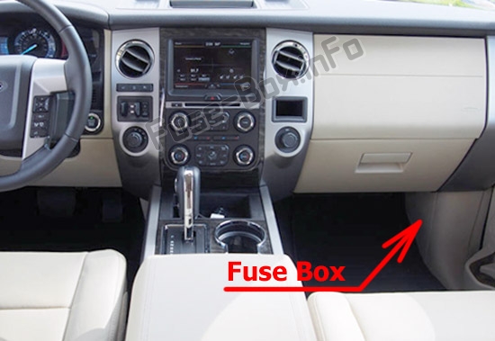
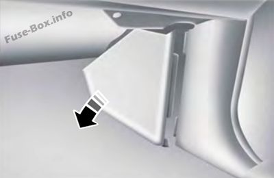
To remove the trim panel for access to the fuse box, pull the panel toward you and swing it out away from the side and remove it.
To reinstall it, line up the tabs with the grooves on the panel, then push it shut.
To remove the fuse box cover, press in the tabs on both sides of the cover, then pull the cover off.
To reinstall the fuse box cover, place the top part of the cover on the fuse panel, then push the bottom part of the cover until you hear it click shut. Gently pull on the cover to make sure it is seated properly.
Engine compartment
The power distribution box is located in the engine compartment.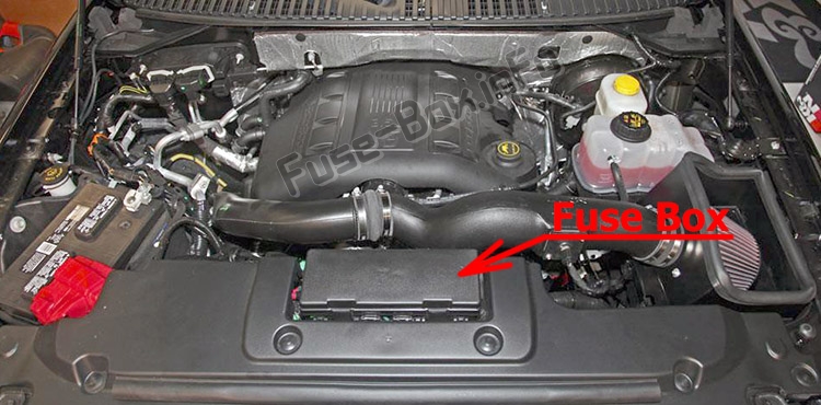
Fuse box diagrams
2015
Passenger compartment
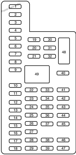
Assignment of the fuses in the Passenger compartment (2015)
| № | Amp rating | Protected circuits |
|---|---|---|
| 1 | 30A | Driver window |
| 2 | 15A | Rear seat control, multimedia gateway module |
| 3 | 30A | Passenger window |
| 4 | 10A | Demand lamps |
| 5 | 20A | Amplifier |
| 6 | 5A | Rear electronic automatic temperature control |
| 7 | 7.5A | Power mirror, driver seat memory switch |
| 8 | — | Not used |
| 9 | 10A | SYNC, power lift gate, electric finish panel, display |
| 10 | 10A | Run accessory relay |
| 11 | 10A | Passive entry/start module |
| 12 | 15A | Interior lighting, puddle lamps |
| 13 | 15A | Right turn and stop/turn signals |
| 14 | 15A | Left turn and stop/turn signals |
| 15 | 15A | Reverse lamp, center high mount stop lamp, EC mirror |
| 16 | 10A | Right front low beam |
| 17 | 10A | Left front low beam |
| 18 | 10A | Brake shift interlock/start button LED/keypad illumination, third row power folding seat, passive entry touch start |
| 19 | — | Not used |
| 20 | 20A | Lock/unlock relays |
| 21 | — | Not used |
| 22 | 20A | Horn |
| 23 | 15A | SWCM, cluster |
| 24 | 15A | Adjustable pedals/power adjustable column, Datalink |
| 25 | 15A | Liftgate release decklid, liftglass release motor |
| 26 | 5A | Push to start switch |
| 27 | 20A | Passive entry/start module |
| 28 | 15A | Ignition switch, key inhibit switch |
| 29 | 20A | Radio, GPS |
| 30 | 15A | Front park lamps |
| 31 | 5A | Trailer brake on/off |
| 32 | 15A | Power vent, rear windows, power inverter |
| 33 | 10A | CCD suspension module |
| 34 | 10A | Rear park assist, rear camera, BLIS, heated seat |
| 35 | 5A | Climate module, 0/D switch |
| 36 | — | Not used |
| 37 | 10A | 4X4 module |
| 38 | 10A | EC mirror, moonroof, DVD, AM/FM radio |
| 39 | 15A | Left and right front high beams |
| 40 | 10A | Rear park/tail lamps |
| 41 | 7.5A | Restraints control module |
| 42 | — | Not used |
| 43 | — | Not used |
| 44 | — | Not used |
| 45 | 5A | Not used (spare) |
| 46 | 10A | Climate control |
| 47 | 15A | Fog lamps |
| 48 | — | Not used |
| 49 | — | Not used |
Engine compartment
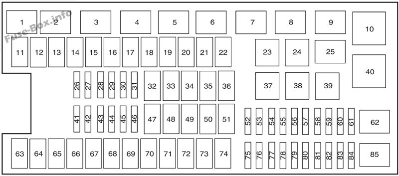
Assignment of the fuses in the Power distribution box (2015)
| № | Amp rating | Protected circuits |
|---|---|---|
| 1 | — | Rear washer relay |
| 2 | — | Starter relay |
| 3 | — | Blower motor relay |
| 4 | — | Rear wiper relay |
| 5 | — | Fuel pump relay |
| 6 | — | Electronic cooling fan |
| 7 | — | Rear window defroster, heated mirror relay |
| 8 | — | Electronic cooling fan |
| 9 | — | Run/start relay |
| 10 | — | Power distribution box relay |
| 11 | 40A** | Power running boards, heated seats |
| 12 | 40A** | Run/start relay |
| 13 | 30A ** | Starter relay |
| 14 | 50A** | Electronic cooling fan |
| 15 | — | Not used |
| 16 | 50A** | Electronic fan |
| 17 | — | Not used |
| 18 | 30A** | Trailer brake |
| 19 | 20A** | Power point (console) |
| 20 | 20A** | 4×4 module relay |
| 21 | 30A** | Trailer tow module |
| 22 | 30A** | Passenger power seat |
| 23 | — | Air conditioner clutch relay |
| 24 | — | Trailer tow park lamp relay |
| 25 | — | Not used |
| 26 | 10 A* | ALT sensor |
| 27 | 20A* | 4×4 all wheel drive module |
| 28 | 25A* | Trailer tow park lamp relay |
| 29 | 10 A* | Integrated wheel end solenoid |
| 30 | 10 A* | Air conditioner clutch relay |
| 31 | 15 A* | Trailer tow back up lamp |
| 32 | 40A** | Blower motor relay |
| 33 | 40A** | 110-volt AC power point |
| 34 | 30A** | Auxiliary blower motor |
| 35 | 50A** | Powertrain control module relay |
| 36 | 30A** | Power liftgate |
| 37 | — | Not used |
| 38 | — | Not used |
| 39 | — | Trailer tow backup lamps relay |
| 40 | — | Electronic fan 2 relay |
| 41 | 10 A* | Powertrain control module keep-alive power |
| 42 | 5A* | Run/start relay |
| 43 | 10 A* | Brake on/off switch |
| 44 | 20A* | Fuel pump relay |
| 45 | 10 A* | Not used (spare) |
| 46 | 15 A* | Front/rear washer pump |
| 47 | 30A** | Rear wiper motor |
| 48 | 40A** | Trailer tow module |
| 49 | — | Not used |
| 50 | 30A** | Front wiper motor relay |
| 51 | 40A** | Rear window defroster and heated mirror relay |
| 52 | 10 A* | Anti-lock brake system run/start feed |
| 53 | 5A* | Powertrain control module ISP |
| 54 | 5A* | Power steering |
| 55 | — | Not used |
| 56 | 30A* | Passenger compartment fuse panel run/start feed |
| 57 | 5A* | Blower motor run/start |
| 58 | — | Not used |
| 59 | 15 A* | Heated mirrors |
| 60 | — | Not used |
| 61 | — | Not used |
| 62 | — | Not used |
| 63 | 25A** | Electronic fan |
| 64 | 30A** | Moonroof |
| 65 | — | Not used |
| 66 | 20A** | Auxiliary power point (rear of center console) |
| 67 | 40A** | Front row climate controlled seats |
| 68 | 30A** | Anti-lock brake system valves |
| 69 | 60A** | Anti-lock brake system pump |
| 70 | 30A** | Third row power fold seat |
| 71 | 20A** | Auxiliary power point/cigar lighter |
| 72 | 20A** | Auxiliary power point (right rear quarter panel) |
| 73 | 30A** | Rear seat climate module |
| 74 | 30A** | Driver power seat |
| 75 | 25A* | Vehicle power 1 – powertrain control module |
| 76 | 20A* | Vehicle power 2 – powertrain control module |
| 77 | 20A* | Vehicle power 4 – ignition coils |
| 78 | — | Not used |
| 79 | 15 A* | Vehicle power 3 – powertrain control module |
| 80 | 5A* | Rain sensor |
| 81 | — | Not used |
| 82 | — | Not used |
| 83 | — | Not used |
| 84 | — | Not used |
| 85 | — | Not used |
| * Mini Fuses ** Cartridge Fuses |
2016
Passenger compartment
Assignment of the fuses in the Passenger compartment (2016)
| № | Amp rating | Protected components |
|---|---|---|
| 1 | 30A | Driver window. |
| 2 | 15A | Rear seat control. Multimedia gateway module. |
| 3 | 30A | Passenger window. |
| 4 | 10A | Demand lamps. |
| 5 | 20A | Amplifier. |
| 6 | 5A | Rear electronic automatic temperature control. |
| 7 | 7.5 A | Power mirror. Driver seat memory switch. |
| 8 | — | Not used. |
| 9 | 10A | SYNC. Power lift gate. Electric finish panel. Display. |
| 10 | 10A | Run accessory relay. |
| 11 | 10A | Passive entry/start module. |
| 12 | 15A | Interior lighting. Puddle lamps. |
| 13 | 15A | Right turn and stop/turn signals. |
| 14 | 15A | Left turn and stop/turn signals. |
| 15 | 15A | Reverse lamp. Center high mount stop lamp. EC mirror. |
| 16 | 10A | Right front low beam. |
| 17 | 10A | Left front low beam. |
| 18 | 10A | Brake shift interlock/start button LED/ keypad illumination. Third row power folding seat. Passive entry touch start. |
| 19 | — | Not used. |
| 20 | 20A | Lock/unlock relays. |
| 21 | — | Not used. |
| 22 | 20A | Horn. |
| 23 | 15A | Steering wheel control module. Cluster. |
| 24 | 15A | Adjustable pedals/power adjustable column. Datalink. |
| 25 | 15A | Liftgate release decklid. Liftglass release motor. |
| 26 | 5A | Push to start switch. |
| 27 | 20A | Passive entry/start module. |
| 28 | 15A | Ignition switch. Key inhibit switch. |
| 29 | 20A | Radio. GPS. |
| 30 | 15A | Front park lamps. |
| 31 | 5A | Trailer brake on/off. |
| 32 | 15A | Power vent. Rear windows. Power inverter. |
| 33 | 10A | CCD suspension module. |
| 34 | 10A | Rear park assist. Rear camera. BUS. Heated seat. |
| 35 | 5A | Climate module. O/D switch. |
| 36 | — | Not used. |
| 37 | 10A | 4X4 module. |
| 38 | 10A | EC mirror. Moonroof. DVD. AM/FM radio. |
| 39 | 15A | Left and right front high beams. |
| 40 | 10A | Rear park/tail lamps. |
| 41 | 7.5 A | Restraints control module. |
| 42 | — | Not used. |
| 43 | — | Not used. |
| 44 | — | Not used. |
| 45 | 5A | Not used (spare). |
| 46 | 10A | Climate control. |
| 47 | 15A | Fog lamps. |
| 48 | — | Not used. |
| 49 | — | Not used. |
Engine compartment
Assignment of the fuses in the Power distribution box (2016)
| № | Amp rating | Protected components |
|---|---|---|
| 1 | Relay | Rear washer relay. |
| 2 | Relay | Starter relay. |
| 3 | Relay | Blower motor relay. |
| 4 | Relay | Rear wiper relay. |
| 5 | Relay | Fuel pump relay. |
| 6 | Relay | Electronic cooling fan. |
| 7 | Relay | Rear window defroster. Heated mirror relay. |
| 8 | Relay | Electronic cooling fan. |
| 9 | Relay | Run/start relay. |
| 10 | Relay | Power distribution box relay. |
| 11 | 40A* | Power running boards. Heated seats. |
| 12 | 40A* | Run/start relay. |
| 13 | 30 A* | Starter relay. |
| 14 | 50A* | Electronic cooling fan. |
| 15 | — | Not used. |
| 16 | 50A* | Electronic fan. |
| 17 | — | Not used. |
| 18 | 30 A* | Trailer brake. |
| 19 | 20A* | Power point (console). |
| 20 | 20A* | 4×4 module HAT 2. |
| 21 | 30 A* | Trailer tow module. |
| 22 | 30 A* | Passenger power seat. |
| 23 | Relay | Air conditioner clutch relay. |
| 24 | Relay | Trailer tow park lamp relay. |
| 25 | — | Not used. |
| 26 | 10 A** | ALT sensor. |
| 27 | 20A** | 4×4 module HAT 1. |
| 28 | 25A** | Trailer tow park lamp relay. |
| 29 | 10 A** | Integrated wheel end solenoid. |
| 30 | 10 A** | Air conditioner clutch relay. |
| 31 | 15A** | Trailer tow back up lamp. |
| 32 | 40A* | Blower motor relay. |
| 33 | 40A* | 110-volt AC power point. |
| 34 | 30 A* | Auxiliary blower motor. |
| 35 | 50A* | Powertrain control module relay. |
| 36 | 30 A* | Power liftgate. |
| 37 | — | Not used. |
| 38 | — | Not used. |
| 39 | Relay | Trailer tow backup lamps relay. |
| 40 | Relay | Electronic fan 2 relay. |
| 41 | 10A** | Powertrain control module keep-alive power. |
| 42 | 5A** | Run/start relay. |
| 43 | 10A** | Brake on/off switch. |
| 44 | 20A** | Fuel pump relay. |
| 45 | 10A** | Not used (spare). |
| 46 | 15A** | Front/rear washer pump. |
| 47 | 30 A* | Rear wiper motor. |
| 48 | 40A* | Trailer tow module. |
| 49 | — | Not used. |
| 50 | 30 A* | Front wiper motor relay. |
| 51 | 40A* | Rear window defroster and heated mirror relay. |
| 52 | 10A** | Anti-lock brake system run/start feed. |
| 53 | 5A** | Powertrain control module ISP. |
| 54 | 5A** | Power steering. |
| 55 | — | Not used. |
| 56 | 30A** | Passenger compartment fuse panel run/ start feed. |
| 57 | 5A** | Blower motor run/start. |
| 58 | — | Not used. |
| 59 | 15A** | Heated mirrors. |
| 60 | — | Not used. |
| 61 | — | Not used. |
| 62 | — | Not used. |
| 63 | 25 A* | Electronic fan. |
| 64 | 30 A* | Moonroof. |
| 65 | — | Not used. |
| 66 | 20A* | Auxiliary power point (rear of center console). |
| 67 | 40A* | Front row climate controlled seats. |
| 68 | 30 A* | Anti-lock brake system valves. |
| 69 | 60A* | Anti-lock brake system pump. |
| 70 | 30 A* | Third row power fold seat. |
| 71 | 20A* | Auxiliary power point/cigar lighter. |
| 72 | 20A* | Auxiliary power point (right rear quarter panel). |
| 73 | 20A* | Rear seat climate module. |
| 74 | 30 A* | Driver power seat. |
| 75 | 25A** | Vehicle power 1 – powertrain control module. |
| 76 | 20A** | Vehicle power 2 – powertrain control module. |
| 77 | 20A** | Vehicle power 4 – ignition coils. |
| 78 | — | Not used. |
| 79 | 15A** | Vehicle power 3 – powertrain control module. |
| 80 | — | Not used. |
| 81 | — | Not used. |
| 82 | 5A** | Rain sensor. |
| 83 | — | Not used. |
| 84 | — | Not used. |
| 85 | Relay | Wiper motor relay. |
| * Cartridge fuses. ** Mini fuses. |
2017
Passenger compartment
Assignment of the fuses in the Passenger compartment (2017)
| № | Amp rating | Protected components |
|---|---|---|
| 1 | 30A | Driver window. |
| 2 | 15A | Rear seat control. Multimedia gateway module. |
| 3 | 30A | Passenger window. |
| 4 | 10A | Demand lamps. |
| 5 | 20A | Amplifier. |
| 6 | 5A | Rear electronic automatic temperature control. |
| 7 | 7.5A | Power mirror. Driver seat memory switch. |
| 8 | — | Not used. |
| 9 | 10A | SYNC. Power lift gate. Electric finish panel. Display. |
| 10 | 10A | Run accessory relay. |
| 11 | 10A | Passive entry/start module. |
| 12 | 15A | Interior lighting. Puddle lamps. |
| 13 | 15A | Right turn and stop/turn signals. |
| 14 | 15A | Left turn and stop/turn signals. |
| 15 | 15A | Reverse lamp. Center high mount stop lamp. EC mirror. |
| 16 | 10A | Right front low beam. |
| 17 | 10A | Left front low beam. |
| 18 | 10A | Brake shift interlock/start button LED/ keypad illumination. Third row power folding seat. Passive entry touch start. |
| 19 | — | Not used. |
| 20 | 20A | Lock/unlock relays. |
| 21 | — | Not used. |
| 22 | 20A | Horn. |
| 23 | 15A | Steering wheel control module. Cluster. |
| 24 | 15A | Adjustable pedals/power adjustable column. Datalink. |
| 25 | 15A | Liftgate release decklid. Liftglass release motor. |
| 26 | 5A | Push to start switch. |
| 27 | 20A | Passive entry/start module. |
| 28 | 15A | Ignition switch. Key inhibit switch. |
| 29 | 20A | Radio. GPS. |
| 30 | 15A | Front park lamps. |
| 31 | 5A | Trailer brake on/off. |
| 32 | 15A | Power vent. Driver’s window motor. Power inverter. |
| 33 | 10A | CCD suspension module. |
| 34 | 10A | Rear park assist. Rear camera. BUS. Heated seat. |
| 35 | 5A | Climate module. O/D switch. |
| 36 | — | Not used. |
| 37 | 10A | 4X4 module. |
| 38 | 10A | EC mirror. Moonroof. DVD. AM/FM radio. |
| 39 | 15A | Left and right front high beams. |
| 40 | 10A | Rear park/tail lamps. |
| 41 | 7.5A | Restraints control module. |
| 42 | — | Not used. |
| 43 | — | Not used. |
| 44 | — | Not used. |
| 45 | 5A | Not used (spare). |
| 46 | 10A | Climate control. |
| 47 | 15A | Fog lamps. |
| 48 | 30A | Front passenger and rear windows circuit breaker. |
| 49 | Relay | Windows and vents relay. |
Engine compartment
Assignment of the fuses in the Power distribution box (2017)
| № | Amp rating | Protected components |
|---|---|---|
| 1 | Relay | Rear washer relay. |
| 2 | Relay | Starter relay. |
| 3 | Relay | Blower motor relay. |
| 4 | Relay | Rear wiper relay. |
| 5 | Relay | Fuel pump relay. |
| 6 | Relay | Electronic cooling fan. |
| 7 | Relay | Rear window defroster. Heated mirror relay. |
| 8 | Relay | Electronic cooling fan. |
| 9 | Relay | Run/start relay. |
| 10 | Relay | Power distribution box relay. |
| 11 | 40A* | Power running boards. Heated seats. |
| 12 | 40A* | Run/start relay. |
| 13 | 30 A* | Starter relay. |
| 14 | 50A* | Electronic cooling fan. |
| 15 | — | Not used. |
| 16 | 50A* | Electronic fan. |
| 17 | — | Not used. |
| 18 | 30 A* | Trailer brake. |
| 19 | 20A* | Power point (console). |
| 20 | 20A* | 4×4 module HAT 2. |
| 21 | 30 A* | Trailer tow module. |
| 22 | 30 A* | Passenger power seat. |
| 23 | Relay | Air conditioner clutch relay. |
| 24 | Relay | Trailer tow park lamp relay. |
| 25 | — | Not used. |
| 26 | 10A** | ALT sensor. |
| 27 | 20A** | 4×4 module HAT 1. |
| 28 | 25A** | Trailer tow park lamp relay. |
| 29 | 10A** | Integrated wheel end solenoid. |
| 30 | 10A** | Air conditioner clutch relay. |
| 31 | 15A** | Trailer tow back up lamp. |
| 32 | 40A* | Blower motor relay. |
| 33 | 40A* | 110-volt AC power point. |
| 34 | 30 A* | Auxiliary blower motor. |
| 35 | 50A* | Powertrain control module relay. |
| 36 | 30 A* | Power liftgate. |
| 37 | — | Not used. |
| 38 | — | Not used. |
| 39 | Relay | Trailer tow backup lamps relay. |
| 40 | Relay | Electronic fan 2 relay. |
| 41 | 10 A** | Powertrain control module keep-alive power. |
| 42 | 5A** | Run/start relay. |
| 43 | 10 A** | Brake on/off switch. |
| 44 | 20A** | Fuel pump relay. |
| 45 | 10 A** | Not used (spare). |
| 46 | 15A** | Front/rear washer pump. |
| 47 | 30 A* | Rear wiper motor. |
| 48 | 40A* | Trailer tow module. |
| 49 | — | Not used. |
| 50 | 30 A* | Front wiper motor relay. |
| 51 | 40A* | Rear window defroster and heated mirror relay. |
| 52 | 10 A** | Anti-lock brake system run/start feed. |
| 53 | 5A** | Powertrain control module ISP. |
| 54 | 5A** | Power steering. |
| 55 | — | Not used. |
| 56 | 30 A** | Passenger compartment fuse panel run/ start feed. |
| 57 | 5A** | Blower motor run/start. |
| 58 | — | Not used. |
| 59 | 15A** | Heated mirrors. |
| 60 | — | Not used. |
| 61 | — | Not used. |
| 62 | — | Not used. |
| 63 | 25 A* | Electronic fan. |
| 64 | 30 A* | Moonroof. |
| 65 | 20A* | Not used (spare). |
| 66 | 20A* | Auxiliary power point (rear of center console). |
| 67 | 40A* | Front row climate controlled seats. |
| 68 | 30 A* | Anti-lock brake system valves. |
| 69 | 60A* | Anti-lock brake system pump. |
| 70 | 30 A* | Third row power fold seat. |
| 71 | 20A* | Auxiliary power point/cigar lighter. |
| 72 | 20A* | Auxiliary power point (right rear quarter panel). |
| 73 | 20A* | Rear seat climate module. |
| 74 | 30 A* | Driver power seat. |
| 75 | 25A** | Vehicle power 1 – powertrain control module. |
| 76 | 20A** | Vehicle power 2 – powertrain control module. |
| 77 | 20A** | Vehicle power 4 – ignition coils. |
| 78 | — | Not used. |
| 79 | 15A** | Vehicle power 3 – powertrain control module. |
| 80 | — | Not used. |
| 81 | — | Not used. |
| 82 | 5A** | Rain sensor. |
| 83 | — | Not used. |
| 84 | — | Not used. |
| 85 | Relay | Wiper motor relay. |


