

Fuse Layout Volvo S60 2015-2018
Contents
Cigar lighter (power outlet) fuses in the Volvo S60 are the fuse #22 (12-volt sockets in tunnel console) in the fuse box “A” under the glove compartment, and fuse #7 (Rear 12-volt socket) in the luggage compartment fuse box.
Table of Contents
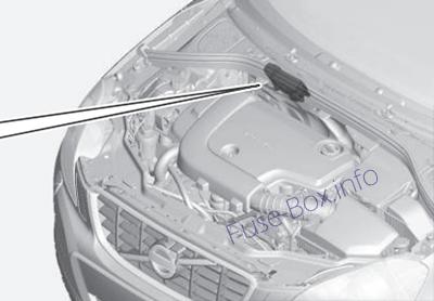
Fuse box location
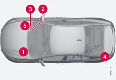
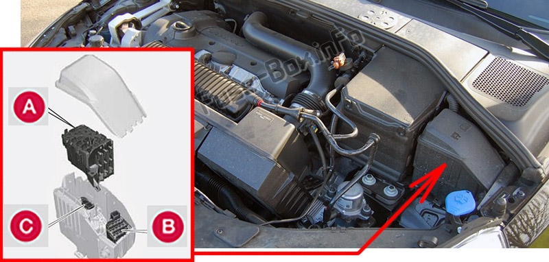
1) Engine compartment
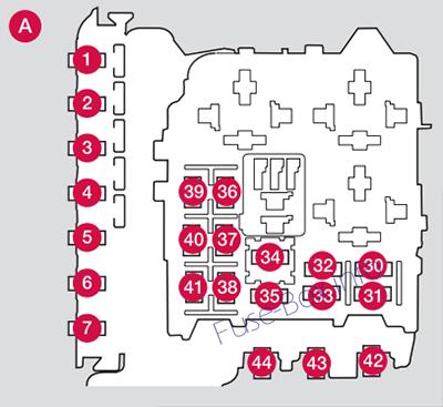
2) Under the glove compartment Fusebox A (General fuses)
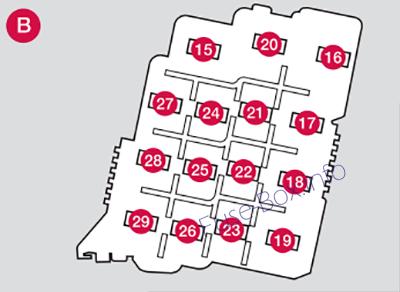
3) Under the glove compartment Fusebox B (Control module fuses)
It is located under the lining.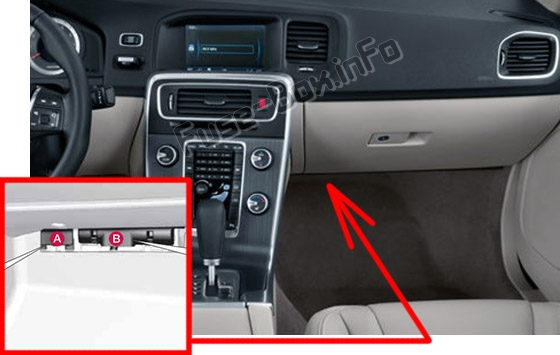
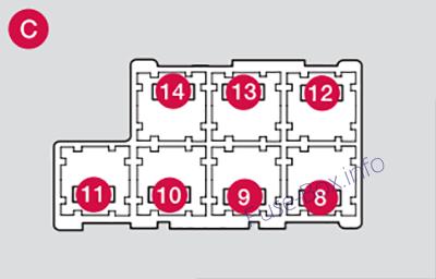
4) Trunk
Located behind the upholstery on the left side of the trunk.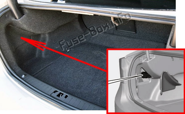
5) Engine compartment cold zone (Start/Stop only)
Fuse box diagrams
2015
Engine compartment
Assignment of fuses in the engine compartment (2015)
| № | Function | A |
|---|---|---|
| 1 | Circuit breaker: central electrical module under the glove compartment (not used on vehicles with the optional Start/Stop function) | 50 |
| 2 | Circuit breaker: central electrical module under the glove compartment | 50 |
| 3 | Circuit breaker: central electrical module in the trunk (not used on vehicles with the optional Start/Stop function) | 60 |
| 4 | Circuit breaker: central electrical module under the glove compartment (not used on vehicles with the optional Start/Stop function) | 60 |
| 5 | Circuit breaker: central electrical module under the glove compartment (not used on vehicles with the optional Start/Stop function) | 60 |
| 6 | – | |
| 7 | – | |
| 8 | Headed windshield (Option), driver’s side | 40 |
| 9 | Windshield wipers | 30 |
| 10 | – | |
| 11 | Climate system blower (not used on vehicles with the optional Start/Stop function) | 40 |
| 12 | Headed windshield (Option), passenger’s side | 40 |
| 13 | ABS pump | 40 |
| 14 | ABS valves | 20 |
| 15 | Headlight washers | 20 |
| 16 | Active Bending Lights-headlight leveling (Option) | 10 |
| 17 | Central electrical module (under the glove compartment) | 20 |
| 18 | ABS | 5 |
| 19 | Adjustable steering force (Option) | 5 |
| 20 | Engine Control Module (ECM), transmission, SRS | 10 |
| 21 | Heated washer nozzles (Option) | 10 |
| 22 | – | |
| 23 | Lighting panel | 5 |
| 24 | – | |
| 25 | – | |
| 26 | – | |
| 27 | Relay coils | 5 |
| 28 | Auxiliary lights (Option) | 20 |
| 29 | Horn | 15 |
| 30 | Relay coils, Engine Control Module (ECM) | 10 |
| 31 | Control module – automatic transmission | 15 |
| 32 | A/C compressor (not 4-cyl. engines) | 15 |
| 33 | Relay-coils A/C, relay coils in engine compartment cold zone for Start/Stop | 5 |
| 34 | Starter motor relay (not used on vehicles with the optional Start/Stop function) | 30 |
| 35 | Engine control module (4-cyl. engines) Ignition coils (5-/6-cyl. engines), condenser (6-cyl. engines) | 20 |
| 36 | Engine Control Module (4-cyl. engines) | 20 |
| 36 | Engine Control Module (5-cyl. & 6-cyl. engines) | 10 |
| 37 | 4-cyl. engines: mass air meter, thermostat, EVAP valve | 10 |
| 37 | 5-/6-cyl. engines: Injection system, mass air meter (6-cyl. engines only), engine control module | 15 |
| 38 | A/C compressor (5-/6-cyl. engines), engine valves, engine control module (6-cyl. engines), solenoids (6-cyl. non-turbo only), mass air meter (6-cyl. only) | 10 |
| 38 | Engine valves/oil pump/center heated oxygen sensor (4-cyl. engines) | 15 |
| 39 | Front/rear heated oxygen sensors (4-cyl. engines), EVAP valve (5-/6-cyl. engines), heated oxygen sensors (5-/6-cyl. engines) | 15 |
| 40 | Oil pump (automatic transmission)/crank-case ventilation heater (5-cyl. engines) | 10 |
| 40 | Ignition coils | 15 |
| 41 | Fuel leakage detection (5-/6-cyl. engines), control module for radiator shutter (5-cyl. engines) | 5 |
| 41 | Fuel leakage detection, A/C relay (4-cyl. engines) | 15 |
| 42 | Coolant pump (4-cyl. engines) | 50 |
| 43 | Cooling fan (4/5-cyl. engines) | 60 |
| 43 | Cooling fan (6-cyl. engines) | 80 |
| 44 | Power steering | 100 |
Under the glove compartment (Fusebox A)
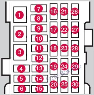
Assignment of fuses under the glove compartment (Fusebox A – 2015)
| № | Function | A |
|---|---|---|
| 1 | Circuit breaker for the infotainment system and for fuses 16-20 | 40 |
| 2 | Windshield washers | 25 |
| 3 | ||
| 4 | ||
| 5 | ||
| 6 | Keyless drive (Option) (door handles) | 5 |
| 7 | ||
| 8 | Controls in driver’s door | 20 |
| 9 | Controls in front passenger’s door | 20 |
| 10 | Controls in right rear passenger’s door | 20 |
| 11 | Controls in left rear passenger’s door | 20 |
| 12 | Keyless drive (Option) | 7.5 |
| 13 | Power driver’s seat (Option) | 20 |
| 14 | Power front passenger’s seat (Option) | 20 |
| 15 | ||
| 16 | Infotainment system control module | 5 |
| 17 | Infotainment system: amplifier, SiriusXM™ satellite radio (Option) | 10 |
| 18 | Infotainment system | 15 |
| 19 | Bluetooth hands-free system | 5 |
| 20 | ||
| 21 | Power moonroof (Option), Courtesy lighting, climate system sensor | 5 |
| 22 | 12-volt sockets in tunnel console | 15 |
| 23 | Heated rear seat (Option) (passenger’s side) | 15 |
| 24 | Heated rear seat (Option) (driver’s side) | 15 |
| 25 | ||
| 26 | Heated front passenger’s seat (Option) | 15 |
| 27 | Heated driver’s seat (Option) | 15 |
| 28 | Park assist (Option), trailer hitch control module (Option), park assist camera(Option), Blind Spot Information System (BLIS) (Option) | 5 |
| 29 | All Wheel Drive (Option) control module | 15 |
| 30 | Active chassis system (Option) | 10 |
Under the glove compartment (Fusebox B)
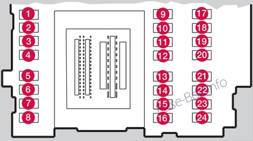
Assignment of fuses under the glove compartment (Fusebox B – 2015)
| № | Function | A |
|---|---|---|
| 1 | ||
| 2 | ||
| 3 | Front courtesy lighting, driver’s door power window controls, power seat(s) (Option), HomeLInk® Wireless Control System (Option) | 7.5 |
| 4 | Instrument panel | 5 |
| 5 | Adaptive cruise control/collision warning (Option) | 10 |
| 6 | Courtesy lighting, rain sensor (Option) | 7.5 |
| 7 | Steering wheel module | 7.5 |
| 8 | Cental locking: fuel filler door | 10 |
| 9 | Electrically heated steering wheel (Option) | 15 |
| 10 | Electrically heated windshield (Option) | 15 |
| 11 | Trunk open | 10 |
| 12 | Electrical folding rear seat outboard head restraints (Option) | 10 |
| 13 | Fuel pump | 20 |
| 14 | Climate system control panel | 5 |
| 15 | ||
| 16 | Alarm, On-board diagnostic system | 5 |
| 17 | ||
| 18 | Airbag system, occupant weight sensor | 10 |
| 19 | Collision warning system (Option) | 5 |
| 20 | Accelerator pedal, auto-dim mirror function, heated rear seats (Option) | 7.5 |
| 21 | – | |
| 22 | Brake lights | 5 |
| 23 | Power moonroof (Option) | 20 |
| 24 | Immobilizer | 5 |
Cargo area
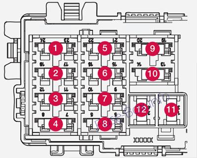
Assignment of fuses in the cargo area
| № | Function | Amp |
|---|---|---|
| 1 | Electric parking brake (left side) | 30 |
| 2 | Electric parking brake (right side) | 30 |
| 3 | Heated rear window | 30 |
| 4 | Trailer socket 2 (Option) | 15 |
| 5 | – | |
| 6 | ||
| 7 | Rear 12-volt socket | 15 |
| 8 | – | – |
| 9 | – | – |
| 10 | – | – |
| 11 | Trailer socket 1 (option) | 40 |
| 12 | – | – |
Engine compartment cold zone
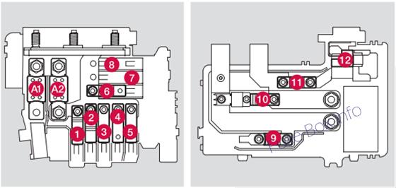
Assignment of fuses in the Engine compartment cold zone (2015)
| № | Function | A |
|---|---|---|
| A1 | Circuit breaker: central electrical module in the engine compartment | 175 |
| A2 | Circuit breaker: fuseboxes under the glove compartment, central electrical module in the trunk | 175 |
| 1 | ||
| 2 | Circuit breaker: fusebox B under the glove compartment | 50 |
| 3 | Circuit breaker: fusebox A under the glove compartment | 60 |
| 4 | Circuit breaker: fusebox A under the glove compartment | 60 |
| 5 | Circuit breaker: central electrical module in the trunk | 60 |
| 6 | Climate system blower | 40 |
| 7 | ||
| 8 | ||
| 9 | Starter motor relay | 30 |
| 10 | Internal diode | 50 |
| 11 | Auxiliary battery | 70 |
| 12 | Central electrical module: auxiliary battery reference voltage, auxiliary battery charging point | 15 |
2016
Engine compartment
Assignment of fuses in the engine compartment (2016)
| № | Function | A |
|---|---|---|
| 1 | Primary fuse for the central electronic module (CEM) under the glovebox (not used on vehicles with the optional Start/Stop function) | 50 |
| 2 | Primary fuse for the central electronic module (CEM) under the glovebox | 50 |
| 3 | Primary fuse for central electrical unit in cargo area (not used on vehicles with the optional Start/Stop function) | 60 |
| 4 | Primary fuse for relay/fuse box under the glovebox | 60 |
| 5 | Primary fuse for relay/fuse box under the glovebox (not used on vehicles with the optional Start/Stop function) | 60 |
| 6 | ||
| 7 | Electric additional heater (not used on vehicles with the optional Start/Stop function) | 100 |
| 8 | Heated windscreen (not used on vehicles with the optional Start/Stop function) , lefthand side | 40 |
| 9 | Windscreen wipers | 30 |
| 10 | Parking heater (Option) | 25 |
| 11 | Ventilation fan (not used on vehicles with the optional Start/Stop function) | 40 |
| 12 | Heated windscreen (not used on vehicles with the optional Start/Stop function) , righthand side | 40 |
| 13 | ABS pump | 40 |
| 14 | ABS valves | 20 |
| 15 | Headlamp washers (Option) | 20 |
| 16 | Headlamp levelling (Option); Active Xenon headlamps – ABL (Option) | 10 |
| 17 | Primary fuse for the central electronic module (CEM) under the glovebox | 20 |
| 18 | ABS | 5 |
| 19 | Adjustable steering force (Option) | 5 |
| 20 | Engine control module; Transmission control module; Airbags | 10 |
| 21 | Heated washer nozzles (Option) | 10 |
| 22 | ||
| 23 | Headlamp control | 5 |
| 24 | ||
| 25 | ||
| 26 | ||
| 27 | Relay coils | 5 |
| 28 | Auxiliary lamps (Option) | 20 |
| 29 | Horn | 15 |
| 30 | Relay coil in main relay for engine management system (4-cyl.); Engine control module (4-cyl.) | 5 |
| 30 | Relay coil in main relay for engine management system (5, 6-cyl.); Engine control module (5, 6-cyl.) | 10 |
| 31 | Transmission control module | 15 |
| 32 | Solenoid clutch A/C (5, 6-cyl. petrol); Supporting coolant pump (4-cyl. diesel) | 15 |
| 33 | Relay coil in relay for solenoid clutch A/C (5, 6-cyl. petrol); Relay coils in central electrical unit in engine compartment cold zone (Start/Stop) | 5 |
| 34 | Start relay (5, 6-cyl. petrol) (not used on vehicles with the optional Start/Stop function) | 30 |
| 35 | Glow control module (5-cyl. diesel) | 10 |
| 35 | Engine control module (4-cyl.); Ignition coils (5, 6-cyl. petrol); Capacitor (6-cyl.) | 20 |
| 36 | Engine control module (5, 6- cyl. petrol) | 10 |
| 36 | Engine control module (5-cyl. diesel) | 15 |
| 36 | Engine control module (4-cyl.) | 20 |
| 37 | Mass air flow sensor (4-cyl.); Thermostat(4-cyl. petrol); EVAP valve (4-cyl. petrol); Cooling pump for EGR (4-cyl. diesel) | 10 |
| 37 | Mass air flow sensor (5-cyl. diesel, 6-cyl.); Control valves (5-cyl. diesel); Injectors (5, 6- cyl. petrol); Engine control module (5, 6-cyl. petrol) | 15 |
| 38 | Solenoid clutch A/C (5, 6-cyl.); Valves (5, 6-cyl.); Engine control module (6-cyl.); Mass air flow sensor (5-cyl. petrol); Oil level sensor | 10 |
| 38 | Valves (4-cyl.); Oil pump (4- cyl. petrol); Lambda-sond, centre (4-cyl. petrol); Lambdasond, rear (4-cyl. diesel) | 15 |
| 39 | Lambda-sond, front (4-cyl.); Lambda-sond, rear (4-cyl. petrol), EVAP valve (5, 6-cyl. petrol); Lambda-sonds (5, 6-cyl.); Control module radiator roller cover (5-cyl. diesel) | 15 |
| 40 | Coolant pump (5-cyl. petrol); Crankcase ventilation heater (5-cyl. petrol); Oil pump automatic gearbox (5-cyl. petrol Start/Stop) | 10 |
| 40 | Ignition coils (4-cyl. petrol) | 15 |
| 40 | Diesel filter heater (diesel) | 20 |
| 41 | Control module, radiator roller cover (5-cyl. petrol) | 5 |
| 41 | Solenoid clutch A/C (4-cyl.); Glow control module (4-cyl. diesel); Oil pump (4-cyl. diesel) | 7.5 |
| 41 | Crankcase ventilation heater (5-cyl. diesel); Oil pump automatic gearbox (5-cyl. diesel Start/Stop) | 10 |
| 42 | Coolant pump (4-cyl. petrol) | 50 |
| 42 | Glow plugs (diesel) | 70 |
| 43 | Cooling fan (4 – 5-cyl. petrol) | 60 |
| 43 | Cooling fan (6-cyl., 4, 5-cyl. diesel) | 80 |
| 44 | Power steering | 100 |
Under the glove compartment (Fusebox A)
Assignment of fuses under the glove compartment (Fusebox A – 2016)
| № | Function | A |
|---|---|---|
| 1 | Primary fuse for audio control module (Option); Primary fuse for fuses 16-20: Infotainment | 40 |
| 2 | Windscreen washers | 25 |
| 3 | – | – |
| 4 | ||
| 5 | ||
| 6 | Door handle (Keyless (Option)) | 5 |
| 7 | – | – |
| 8 | Control panel, driver’s door | 20 |
| 9 | Control panel, front passenger door | 20 |
| 10 | Control panel, rear passenger door, right | 20 |
| 11 | Control panel, rear passenger door, left | 20 |
| 12 | Keyless (Option) | 7.5 |
| 13 | Power seat, driver’s side (Option) | 20 |
| 14 | Power seat, passenger side (Option) | 20 |
| 15 | ||
| 16 | Infotainment Control Module or Screen | 5 |
| 17 | Audio control unit (amplifier) (Option); TV (Option); Digital radio (Option) | 10 |
| 18 | Audio control module or Control module Sensus | 15 |
| 19 | Telematics (Option); Bluetooth (Option) | 5 |
| 20 | ||
| 21 | Sunroof(Option); Interior lighting roof; Climate sensor (Option); Damper motors, air intake | 5 |
| 22 | 12 V socket, tunnel console | 15 |
| 23 | Seat heating, rear right (Option) | 15 |
| 24 | Seat heating, rear left (Option) | 15 |
| 25 | Electric additional heater (Option) | 5 |
| 26 | Seat heating, front passenger side | 15 |
| 27 | Seat heating, front driver’s side | 15 |
| 28 | Parking assistance (Option); Parking camera (Option); BLIS (Option) | 5 |
| 29 | AWD control module (Option) | 15 |
| 30 | Active chassis Four-C (Option) | 10 |
Under the glove compartment (Fusebox B)
Assignment of fuses under the glove compartment (Fusebox B – 2016)
| № | Function | A |
|---|---|---|
| 1 | ||
| 2 | ||
| 3 | Interior lighting; Driver’s door control panel, power windows; Power seats (Option) | 7.5 |
| 4 | Combined instrument panel | 5 |
| 5 | Adaptive cruise control, ACC collision warning system (Option) | 10 |
| 6 | Interior lighting; Rain sensor (Option) | 7.5 |
| 7 | Steering wheel module | 7.5 |
| 8 | Central locking system, fuel filler flap | 10 |
| 9 | Heated steering wheel (Option) | 15 |
| 10 | Heated windscreen (Option) | 15 |
| 11 | Unlocking, boot lid | 10 |
| 12 | Folding head restraint (Option) | 10 |
| 13 | Fuel pump | 20 |
| 14 | Movement detector alarm (Option); Climate panel | 5 |
| 15 | Steering lock | 15 |
| 16 | Siren (Option); Data link connector OBDII | 5 |
| 17 | – | – |
| 18 | Airbags | 10 |
| 19 | Collision warning system (Option) | 5 |
| 20 | Accelerator pedal sensor; Dimming interior rearview mirror (Option); Seat heating, rear (Option) | 7.5 |
| 21 | Infotainment control module (Performance); Audio (Performance) | 15 |
| 22 | Brake light | 5 |
| 23 | Sunroof (Option) | 20 |
| 24 | Immobiliser | 5 |
Cargo area
Assignment of fuses in the cargo area
| № | Function | Amp |
|---|---|---|
| 1 | Electric parking brake (left side) | 30 |
| 2 | Electric parking brake (right side) | 30 |
| 3 | Heated rear window | 30 |
| 4 | Trailer socket 2 (Option) | 15 |
| 5 | – | |
| 6 | ||
| 7 | Rear 12-volt socket | 15 |
| 8 | – | – |
| 9 | – | – |
| 10 | – | – |
| 11 | Trailer socket 1 (option) | 40 |
| 12 | – | – |
Engine compartment cold zone
Assignment of fuses in the Engine compartment cold zone (2016)
| № | Function | A |
|---|---|---|
| A1 | Main fuse for central electrical unit in the engine compartment | 175 |
| A2 | Main fuse for central electronic module (CEM) under the glovebox, relay/fuse box under the glovebox, central electrical unit in cargo area | 175 |
| 1 | Electric additional heater* | 100 |
| 2 | Primary fuse for the central electronic module (CEM) under the glovebox | 50 |
| 3 | Primary fuse for relay/fuse box under the glovebox | 60 |
| 4 | Heated windscreen (option) | 60 |
| 5 | Primary fuse for central electrical unit in cargo area | 60 |
| 6 | Ventilation fan | 40 |
| 7 | ||
| 8 | ||
| 9 | Start relay | 30 |
| 10 | ||
| 11 | Support battery | 70 |
| 12 | Central electronic module (CEM) – reference voltage support battery | 5 |
2017
Engine compartment
Assignment of fuses in the engine compartment (2017)
| № | Function | A |
|---|---|---|
| 1 | Primary fuse for the central electronic module (CEM) under the glovebox (not used on vehicles with the optional Start/Stop function) | 50 |
| 2 | Primary fuse for the central electronic module (CEM) under the glovebox | 50 |
| 3 | Primary fuse for central electrical unit in cargo area (not used on vehicles with the optional Start/Stop function) | 60 |
| 4 | Primary fuse for relay/fuse box under the glovebox | 60 |
| 5 | Primary fuse for relay/fuse box under the glovebox (not used on vehicles with the optional Start/Stop function) | 60 |
| 6 | ||
| 7 | Electric additional heater (not used on vehicles with the optional Start/Stop function) | 100 |
| 8 | Heated windscreen (not used on vehicles with the optional Start/Stop function) , lefthand side | 40 |
| 9 | Windscreen wipers | |
| 10 | Parking heater (Option) | |
| 11 | Ventilation fan (not used on vehicles with the optional Start/Stop function) | |
| 12 | Heated windscreen (not used on vehicles with the optional Start/Stop function), right-hand side | 40 |
| 13 | ABS pump | 40 |
| 14 | ABS valves | 20 |
| 15 | Headlamp washers (Option) | 20 |
| 16 | Headlamp levelling (Option); Active Xenon headlamps – ABL (Option) | 10 |
| 17 | Primary fuse for the central electronic module (CEM) under the glovebox | 20 |
| 18 | ABS | 5 |
| 19 | Adjustable steering force (Option) | 5 |
| 20 | Engine control module; Transmission control module; Airbags | 10 |
| 21 | Heated washer nozzles (Option) | 10 |
| 22 | – | – |
| 23 | Headlamp control | 5 |
| 24 | – | – |
| 25 | – | – |
| 26 | – | – |
| 27 | Relay coils | 5 |
| 28 | Auxiliary lamps (Option) | 20 |
| 29 | Horn | 15 |
| 30 | Relay coil in main relay for engine management system (4-cyl.); Engine control module (4-cyl.) | 5 |
| 30 | Relay coil in main relay for engine management system (5-cyl. diesel); Engine control module (5-cyl. diesel) | 10 |
| 31 | Transmission control module | 15 |
| 32 | Supporting coolant pump (4-cyl. diesel) | 15 |
| 33 | Relay coils in central electrical unit in engine compartment cold zone Start/Stop | 5 |
| 34 | – | – |
| 35 | Glow control module (5-cyl. diesel) | 10 |
| 35 | Engine control module (4-cyl.) 20 | 20 |
| 36 | Engine control module (5-cyl. diesel) | 15 |
| 36 | Engine control module (4-cyl.) | 20 |
| 37 | Mass air flow sensor (4-cyl.); Thermostat(4-cyl. petrol); EVAP valve (4-cyl. petrol); Cooling pump for EGR (4-cyl. diesel) | 10 |
| 37 | Mass airflow meter (5-cyl. diesel); Control valves (5-cyl. diesel) | 15 |
| 38 | Solenoid clutch A/C (5-cyl. diesel); Valves (5-cyl. diesel); Oil level sensor | 10 |
| 38 | Valves (4-cyl.); Oil pump (4-cyl. petrol); Lambda-sond, centre (4-cyl. petrol); Lambda-sond, rear (4-cyl. diesel) | 15 |
| 39 | Lambda-sond, front (4-cyl.); Lambda-sond, rear (4-cyl. petrol) Lambda-sonds (5-cyl. diesel); Control module, radiator roller cover (5-cyl. diesel) | 15 |
| 40 | Ignition coils (4-cyl. petrol) | 15 |
| 40 | Diesel filter heater (diesel) | 20 |
| 41 | Solenoid clutch A/C (4-cyl.); Glow control module (4-cyl. diesel); Oil pump (4-cyl. diesel) | 7.5 |
| 41 | Crankcase ventilation heater (5-cyl. diesel); Oil pump automatic gearbox (5-cyl. diesel Start/Stop) | 10 |
| 42 | Coolant pump (4-cyl. petrol) | 50 |
| 42 | Glow plugs (diesel) | 70 |
| 43 | Cooling fan (petrol) (Depending on cooling fan variant) | 60/80 |
| 43 | Cooling fan (diesel) | 80 |
| 44 | Power steering | 100 |
Under the glove compartment (Fusebox A)
Assignment of fuses under the glove compartment (Fusebox A – 2017)
| № | Function | A |
|---|---|---|
| 1 | Primary fuse for audio control module (Option); Primary fuse for fuses 16-20: Infotainment | 40 |
| 2 | Windscreen washers | 25 |
| 3 | – | – |
| 4 | ||
| 5 | ||
| 6 | Door handle (Keyless (Option)) | 5 |
| 7 | – | – |
| 8 | Control panel, driver’s door | 20 |
| 9 | Control panel, front passenger door | 20 |
| 10 | Control panel, rear passenger door, right | 20 |
| 11 | Control panel, rear passenger door, left | 20 |
| 12 | Keyless (Option) | 7.5 |
| 13 | Power seat, driver’s side (Option) | 20 |
| 14 | Power seat, passenger side (Option) | 20 |
| 15 | ||
| 16 | Infotainment Control Module or Screen | 5 |
| 17 | Audio control unit (amplifier) (Option); TV (Option); Digital radio (Option) | 10 |
| 18 | Audio control module or Control module Sensus | 15 |
| 19 | Telematics (Option); Bluetooth (Option) | 5 |
| 20 | ||
| 21 | Sunroof(Option); Interior lighting roof; Climate sensor (Option); Damper motors, air intake | 5 |
| 22 | 12 V socket, tunnel console | 15 |
| 23 | Seat heating, rear right (Option) | 15 |
| 24 | Seat heating, rear left (Option) | 15 |
| 25 | Electric additional heater (Option) | 5 |
| 26 | Seat heating, front passenger side | 15 |
| 27 | Seat heating, front driver’s side | 15 |
| 28 | Parking assistance (Option); Parking camera (Option); BLIS (Option) | 5 |
| 29 | AWD control module (Option) | 15 |
| 30 | Active chassis Four-C (Option) | 10 |
Under the glove compartment (Fusebox B)
Assignment of fuses under the glove compartment (Fusebox B – 2017)
| № | Function | A |
|---|---|---|
| 1 | ||
| 2 | ||
| 3 | Interior lighting; Driver’s door control panel, power windows; Power seats* | 7.5 |
| 4 | Combined instrument panel | 5 |
| 5 | Adaptive cruise control, ACC collision warning system* | 10 |
| 6 | Interior lighting; Rain sensor (Option) | 7.5 |
| 7 | Steering wheel module | 7.5 |
| 8 | Central locking system, fuel filler flap | 10 |
| 9 | Heated steering wheel (Option) | 15 |
| 10 | Heated windscreen (Option) | 15 |
| 11 | Unlocking, boot lid | 10 |
| 12 | Folding head restraint (Option) | 10 |
| 13 | Fuel pump | 20 |
| 14 | Movement detector alarm (Option); Climate panel | 5 |
| 15 | Steering lock | 15 |
| 16 | Siren (Option); Data link connector OBDII | 5 |
| 17 | – | – |
| 18 | Airbags | 10 |
| 19 | Collision warning system (Option) | 5 |
| 20 | Accelerator pedal sensor; Dimming interior rearview mirror (Option); Seat heating, rear (Option) | 7.5 |
| 21 | Infotainment control module (Performance); Audio (Performance) | 15 |
| 22 | Brake light | 5 |
| 23 | Sunroof (Option) | 20 |
| 24 | Immobiliser | 5 |
Cargo area
Assignment of fuses in the cargo area
| № | Function | Amp |
|---|---|---|
| 1 | Electric parking brake (left side) | 30 |
| 2 | Electric parking brake (right side) | 30 |
| 3 | Heated rear window | 30 |
| 4 | Trailer socket 2 (Option) | 15 |
| 5 | – | |
| 6 | ||
| 7 | Rear 12-volt socket | 15 |
| 8 | – | – |
| 9 | – | – |
| 10 | – | – |
| 11 | Trailer socket 1 (option) | 40 |
| 12 | – | – |
Engine compartment cold zone
Assignment of fuses in the Engine compartment cold zone (2017)
| № | Function | A |
|---|---|---|
| A1 | Main fuse for central electrical unit in the engine compartment | 175 |
| A2 | Main fuse for central electronic module (CEM) under the glovebox, relay/fuse box under the glovebox, central electrical unit in cargo area | 175 |
| 1 | Electric additional heater (Option) | 100 |
| 2 | Primary fuse for the central electronic module (CEM) under the glovebox | 50 |
| 3 | Primary fuse for relay/fuse box under the glovebox | 60 |
| 4 | Heated windscreen (Option) | 60 |
| 5 | Primary fuse for central electrical unit in cargo area | 60 |
| 6 | Ventilation fan | 40 |
| 7 | ||
| 8 | ||
| 9 | Start relay | 30 |
| 10 | ||
| 11 | Support battery | 70 |
| 12 | Central electronic module (CEM) – reference voltage support battery | 5 |
2018
Engine compartment
Assignment of fuses in the engine compartment (2018)
| № | Function | A |
|---|---|---|
| 1 | Circuit breaker: central electrical module under the glove compartment (not used on vehicles with the optional Start/Stop function) | 50 |
| 2 | Circuit breaker: central electrical module under the glove compartment | 50 |
| 3 | Circuit breaker: central electrical module in the trunk (not used on vehicles with the optional Start/Stop function) | 60 |
| 4 | Circuit breaker: central electrical module under the glove compartment (not used on vehicles with the optional Start/Stop function) | 60 |
| 5 | Circuit breaker: central electrical module under the glove compartment (not used on vehicles with the optional Start/Stop function) | 60 |
| 6 | – | |
| 7 | – | |
| 8 | Headed windshield (Option), driver’s side | 40 |
| 9 | Windshield wipers | 30 |
| 10 | – | |
| 11 | Climate system blower (not used on vehicles with the optional Start/Stop function) | 40 |
| 12 | Headed windshield (Option), passenger’s side | 40 |
| 13 | ABS pump | 40 |
| 14 | ABS valves | 20 |
| 15 | Headlight washers | 20 |
| 16 | Active Bending Lights-headlight leveling (Option) | 10 |
| 17 | Central electrical module (under the glove compartment) | 20 |
| 18 | ABS | 5 |
| 19 | Adjustable steering force (Option) | 5 |
| 20 | Engine Control Module (ECM), transmission, SRS | 10 |
| 21 | Heated washer nozzles (Option) | 10 |
| 22 | – | |
| 23 | Lighting panel | 5 |
| 24 | – | |
| 25 | – | |
| 26 | – | |
| 27 | Relay coils | 5 |
| 28 | Auxiliary lights (Option) | 20 |
| 29 | Horn | 15 |
| 30 | Relay coils, Engine Control Module (ECM) | 10 |
| 31 | Control module – automatic transmission | 15 |
| 32 | A/C compressor (not 4-cyl. engines) | 15 |
| 33 | Relay-coils A/C, relay coils in engine compartment cold zone for Start/Stop | 5 |
| 34 | Starter motor relay (not used on vehicles with the optional Start/Stop function) | 30 |
| 35 | Engine control module (4-cyl. engines) Ignition coils (5 cyl. engines) | 20 |
| 36 | Engine Control Module (4-cyl. engines) | 20 |
| 36 | Engine Control Module (5-cyl. engines) | 10 |
| 37 | 4-cyl. engines: mass air meter, thermostat, EVAP valve | 10 |
| 37 | 5-cyl. engines: Injection system, engine control module | 15 |
| 38 | A/C compressor (5-cyl. engines), engine valves, oil level sensor (5-cyl. only) | 10 |
| 38 | Engine valves/oil pump/ center heated oxygen sensor (4-cyl. engines) | 15 |
| 39 | Front/rear heated oxygen sensors (4-cyl. engines), EVAP valve (5-cyl. engines), heated oxygen sensors (5-cyl. engines) | 15 |
| 40 | Oil pump/crankcase ventilation heater/coolant pump (5-cyl. engines) | 10 |
| 40 | Ignition coils (4-cyl. engines) | 15 |
| 41 | Fuel leakage detection (5-cyl. engines), control module for radiator shutter (5-cyl. engines) | 5 |
| 41 | Fuel leakage detection, A/C solenoid (4-cyl. engines) | 7.5 |
| 42 | Coolant pump (4-cyl. engines) | 50 |
| 43 | Cooling fan | 60 or 80 (4-cyl. engines), 60 (5-cyl. engines) |
| 44 | Power steering | 100 |
Under the glove compartment (Fusebox A)
Assignment of fuses under the glove compartment (Fusebox A – 2018)
| № | Function | A |
|---|---|---|
| 1 | Circuit breaker for the infotainment system and for fuses 16-20 | 40 |
| 2 | Windshield washers | 25 |
| 3 | – | |
| 4 | – | |
| 5 | – | |
| 6 | Keyless drive (Option) (door handles) | 5 |
| 7 | – | |
| 8 | Controls in driver’s door | 20 |
| 9 | Controls in front passenger’s door | 20 |
| 10 | Controls in right rear passenger’s door | 20 |
| 11 | Controls in left rear passenger’s door | 20 |
| 12 | Keyless drive (Option) | 7.5 |
| 13 | Power driver’s seat (Option) | 20 |
| 14 | Power front passenger’s seat (Option) | 20 |
| 15 | – | |
| 16 | Infotainment system display | 5 |
| 17 | Infotainment system: amplifier, Sir-iusXM satellite radio (Option) | 10 |
| 18 | Sensus control module | 15 |
| 19 | Bluetooth hands-free system | 5 |
| 20 | ||
| 21 | Power moonroof (Option), Courtesy lighting, climate system sensor | 5 |
| 22 | 12-volt sockets in tunnel console | 15 |
| 23 | Heated rear seat (passenger’s side) (Option) | 15 |
| 24 | Heated rear seat (driver’s side) (Option) | 15 |
| 25 | – | |
| 26 | Heated front passenger’s seat (Option) | 15 |
| 27 | Heated driver’s seat (Option) | 15 |
| 28 | Park assist (Option), Blind Spot Information System (BUS) (Option), park assist camera (Option) | 5 |
| 29 | All Wheel Drive control module (Option) | 15 |
| 30 | Active chassis system (Option) | 10 |
Under the glove compartment (Fusebox B)
Assignment of fuses under the glove compartment (Fusebox B – 2018)
| № | Function | A |
|---|---|---|
| 1 | – | |
| 2 | – | |
| 3 | Front courtesy lighting, driver’s door power window controls, power seat(s) (Option), | 7.5 |
| 4 | Instrument panel | 5 |
| 5 | Adaptive cruise control/collision warning (Option) | 10 |
| 6 | Courtesy lighting, rain sensor (Option), HomeLInk (Option), Wireless Control System (Option) | 7.5 |
| 7 | Steering wheel module | 7.5 |
| 8 | Cental locking: fuel filler door | 10 |
| 9 | Electrically heated steering wheel (Option) | 15 |
| 10 | Electrically heated windshield (Option) | 15 |
| 11 | Trunk open | 10 |
| 12 | Electrical folding rear seat outboard head restraints (Option) | 10 |
| 13 | Fuel pump | 20 |
| 14 | Climate system control panel | 5 |
| 15 | ||
| 16 | Alarm, On-board diagnostic system | 5 |
| 17 | Satellite radio (Option), audio system amplifier | 10 |
| 18 | Airbag system, occupant weight sensor | 10 |
| 19 | Collision warning system | 5 |
| 20 | Accelerator pedal sensor, auto-dim mirror function, heated rear seats (Option) | 7.5 |
| 21 | – | |
| 22 | Brake lights | 5 |
| 23 | Power moonroof (Option) | 20 |
| 24 | Immobilizer | 5 |
Cargo area
Assignment of fuses in the cargo area
| № | Function | Amp |
|---|---|---|
| 1 | Electric parking brake (left side) | 30 |
| 2 | Electric parking brake (right side) | 30 |
| 3 | Heated rear window | 30 |
| 4 | Trailer socket 2 (Option) | 15 |
| 5 | – | |
| 6 | ||
| 7 | Rear 12-volt socket | 15 |
| 8 | – | – |
| 9 | – | – |
| 10 | – | – |
| 11 | Trailer socket 1 (option) | 40 |
| 12 | – | – |
Engine compartment cold zone
Assignment of fuses in the Engine compartment cold zone (2018)
| № | Function | A |
|---|---|---|
| A1 | Circuit breaker: central electrical module in the engine compartment | 175 |
| A2 | Circuit breaker: fuseboxes under the glove compartment, central electrical module in the trunk | 175 |
| 1 | ||
| 2 | Circuit breaker: fusebox B under the glove compartment | 50 |
| 3 | Circuit breaker: fusebox A under the glove compartment | 60 |
| 4 | Circuit breaker: fusebox A under the glove compartment | 60 |
| 5 | Circuit breaker: central electrical module in the trunk | 60 |
| 6 | Climate system blower | 40 |
| 7 | ||
| 8 | ||
| 9 | Starter motor relay | 30 |
| 10 | Internal diode | 50 |
| 11 | Auxiliary battery | 70 |
| 12 | Central electrical module: auxiliary battery reference voltage, auxiliary battery charging point | 15 |


