


Fuse Layout Volvo S60 2011-2014
Contents
Cigar lighter (power outlet) fuses in the Volvo S60 are the fuse #22 (12-volt sockets) in the fuse box “A” under the glove compartment, and fuse #7 (Rear 12-volt socket) in the luggage compartment fuse box.
Table of Contents
Fuse box location
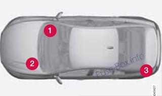
1) Under the glove compartment
The fuse box is located under the lining.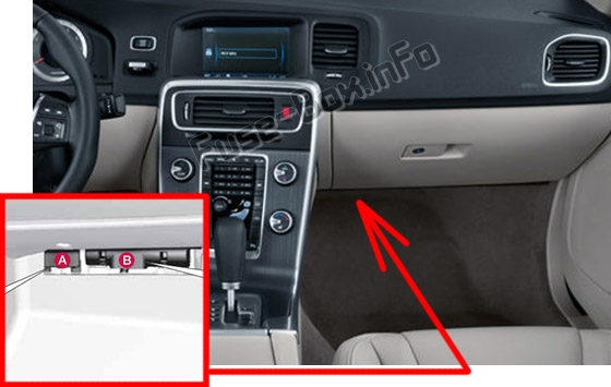
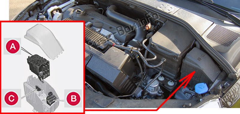
2) Engine compartment
3) Trunk
Located behind the upholstery on the left side of the trunk.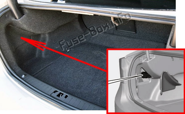
Fuse box diagrams
2011
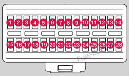
Engine compartment
Assignment of fuses in the engine compartment (2011)
| № | Function | Amp |
|---|---|---|
| 1 | Circuit breaker | 50 |
| 2 | Circuit breaker | 50 |
| 3 | Circuit breaker | 60 |
| 4 | Circuit breaker | 60 |
| 5 | Circuit breaker | 60 |
| 6 | – | |
| 7 | – | |
| 8 | Headlight washers (Option) | 20 |
| 9 | Windshield wipers | 30 |
| 10 | ||
| 11 | Climate system blower | 40 |
| 12 | ||
| 13 | ABS pump | 40 |
| 14 | ABS valves | 20 |
| 15 | ||
| 16 | Active Bending Lights-headlight leveling (Option) | 10 |
| 17 | Central electrical module | 20 |
| 18 | ABS 15 feed | 5 |
| 19 | Speed-dependent steering force (Option) | 5 |
| 20 | Engine Control Module (ECM), transmission, SRS | 10 |
| 21 | Heated washer nozzles (Option) | 10 |
| 22 | Vacuum pump I5T | 5 |
| 23 | Lighting panel | 5 |
| 24 | ||
| 25 | ||
| 26 | ||
| 27 | Relay – engine compartment box | 5 |
| 28 | Auxiliary lights (Option) | 20 |
| 29 | Horn | 15 |
| 30 | Engine Control Module (ECM) | 10 |
| 31 | Control module – automatic transmission | 15 |
| 32 | A/C compressor | 15 |
| 33 | Relay-coils | 5 |
| 34 | Starter motor relay | 30 |
| 35 | Ignition coils | 20 |
| 36 | Engine Control Module (ECM), throttle | 10 |
| 37 | ||
| 38 | Engine valves | 10 |
| 39 | EVAP/heated oxygen sensor/fuel injection | 15 |
| 40 | ||
| 41 | Fuel leakage detection | 5 |
| 42 | ||
| 43 | Cooling fan | 80 |
| 44 | Electro-hydraulic power steering | 100 |
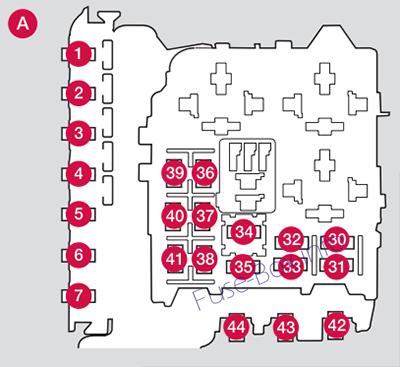
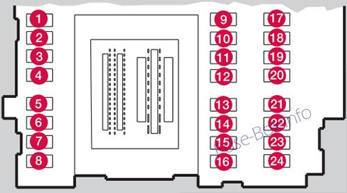
Under the glove compartment (Fusebox A)
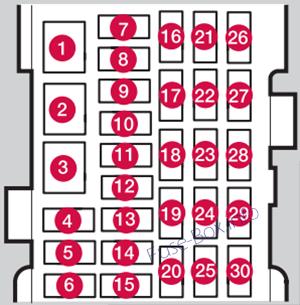
Assignment of fuses under the glove compartment (Fusebox A – 2011)
| № | Function | A |
|---|---|---|
| 1 | Circuit breaker – infotainment system | 40 |
| 2 | ||
| 3 | ||
| 4 | ||
| 5 | ||
| 6 | Keyless drive (Option) (door handles) | 5 |
| 7 | ||
| 8 | Controls in driver’s door | 20 |
| 9 | Controls in front passenger’s door | 20 |
| 10 | Controls in right rear passenger’s door | 20 |
| 11 | Controls in left rear passenger’s door | 20 |
| 12 | Keyless drive (Option) | 7.5 |
| 13 | Power driver’s seat (Option) | 20 |
| 14 | Power front passenger’s seat (Option) | 20 |
| 15 | Folding rear seat head restraints | 15 |
| 16 | Infotainment control module | 5 |
| 17 | Infotainment system, Navigation system(Option) display | 10 |
| 18 | Infotainment system | 15 |
| 19 | Bluetooth hands-free system | 5 |
| 20 | ||
| 21 | Power moonroof (Option), Courtesy lighting, climate system sensor | 5 |
| 22 | 12-volt sockets | 15 |
| 23 | Heated front passenger’s seat (Option) | 15 |
| 24 | Heated driver’s seat (Option) | 15 |
| 25 | ||
| 26 | Heated rear passenger’s seat (right) (Option) | 15 |
| 27 | Heated rear passenger’s seat (left) (Option) | 15 |
| 28 | Park assist (Option), Volvo Navigation System (Option), Park assist camera(Option) | 5 |
| 29 | All Wheel Drive(Option) control module | 5 |
| 30 | Active chassis system (Option) | 10 |
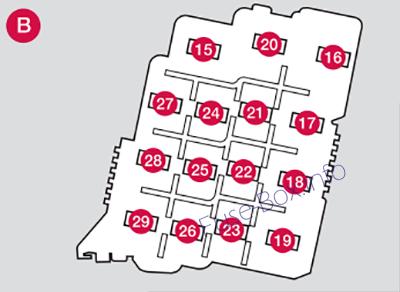
Under the glove compartment (Fusebox B)
Assignment of fuses under the glove compartment (Fusebox B – 2011)
| № | Function | Amp |
|---|---|---|
| 1 | ||
| 2 | ||
| 3 | Front courtesy lighting, power seat(s) (Option) | 7.5 |
| 4 | Instrument panel information display | 5 |
| 5 | Adaptive cruise control/collision warning (Option) | 10 |
| 6 | Courtesy lighting, rain sensor (Option) | 7.5 |
| 7 | Steering wheel module | 7.5 |
| 8 | Rear cental locking and fuel filler door | 10 |
| 9 | Washers | 15 |
| 10 | Windshield washer | 15 |
| 11 | Trunk unlock | 10 |
| 12 | – | |
| 13 | Fuel pump | 20 |
| 14 | Remote key receiver, Alarm, Climate system | 5 |
| 15 | Steering wheel lock | 15 |
| 16 | Alarm, On-board diagnostic system | 5 |
| 17 | – | |
| 18 | Airbag system, Occupant weight system | 10 |
| 19 | Adaptive cruise control front radar (Option) | 5 |
| 20 | Accelerator pedal, power door mirrors, Heated rear seats (Option) | 7.5 |
| 21 | Infotainment system, CD and radio | 15 |
| 22 | Brake lights | 5 |
| 23 | Power moonroof (Option) | 20 |
| 24 | Immobilizer | 5 |
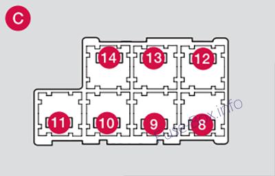
Cargo area
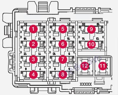
Assignment of fuses in the cargo area
| № | Function | Amp |
|---|---|---|
| 1 | Electric parking brake (left side) | 30 |
| 2 | Electric parking brake (right side) | 30 |
| 3 | Heated rear window | 30 |
| 4 | Trailer socket 2 (Option) | 15 |
| 5 | – | |
| 6 | ||
| 7 | Rear 12-volt socket | 15 |
| 8 | – | – |
| 9 | – | – |
| 10 | – | – |
| 11 | Trailer socket 1 (option) | 40 |
| 12 | – | – |
2012
Engine compartment
Assignment of fuses in the engine compartment (2012)
| № | Function | Amp |
|---|---|---|
| 1 | Circuit breaker | 50 |
| 2 | Circuit breaker | 50 |
| 3 | Circuit breaker | 60 |
| 4 | Circuit breaker | 60 |
| 5 | Circuit breaker | 60 |
| 6 | – | |
| 7 | – | |
| 8 | Headlight washers (Option) | 20 |
| 9 | Windshield wipers | 30 |
| 10 | – | |
| 11 | Climate system blower | 40 |
| 12 | – | |
| 13 | ABS pump | 40 |
| 14 | ABS valves | 20 |
| 15 | – | |
| 16 | Active Bending Lights-headlight leveling (Option) | 10 |
| 17 | Central electrical module | 20 |
| 18 | ABS | 5 |
| 19 | Speed-dependent steering force (Option) | 5 |
| 20 | Engine Control Module (ECM), transmission, SRS | 10 |
| 21 | Heated washer nozzles (Option) | 10 |
| 22 | Vacuum pump (5-cylinder engine) | 5 |
| 23 | Lighting panel | 5 |
| 24 | – | |
| 25 | – | |
| 26 | – | |
| 27 | Relay – engine compartment box | 5 |
| 28 | Auxiliary lights (Option) | 20 |
| 29 | Horn | 15 |
| 30 | Engine Control Module (ECM) | 10 |
| 31 | Control module – automatic transmission | 15 |
| 32 | A/C compressor | 15 |
| 33 | Relay-coils | 5 |
| 34 | Starter motor relay | 30 |
| 35 | Ignition coils | 20 |
| 36 | Engine Control Module | 10 |
| 37 | Injection system, mass air meter | 15 |
| 38 | A/C compressor, engine valves, engine control module | 10 |
| 39 | EVAP valve, heated oxygen sensor | 15 |
| 40 | Vacuum pump/crankcase ventilation heater (5-cylin-der engine) | 20 |
| 41 | Fuel leakage detection | 5 |
| 42 | ||
| 43 | Cooling fan | 60 (5- cyl. engi ne) 80 (6- cyl. engi ne) |
| 44 | Electro-hydraulic power steering | 100 |
Under the glove compartment (Fusebox A)
Assignment of fuses under the glove compartment (Fusebox A – 2012)
| № | Function | A |
|---|---|---|
| 1 | Circuit breaker – infotainmerit system | 40 |
| 2 | ||
| 3 | ||
| 4 | ||
| 5 | ||
| 6 | Keyless drive (Option) (door handles) | 5 |
| 7 | ||
| 8 | Controls in driver’s door | 20 |
| 9 | Controls in front passenger’s door | 20 |
| 10 | Controls in right rear passenger’s door | 20 |
| 11 | Controls in left rear passenger’s door | 20 |
| 12 | Keyless drive (Option) | 7.5 |
| 13 | Power driver’s seat (Option) | 20 |
| 14 | Power front passenger’s seat (Option) | 20 |
| 15 | Folding rear seat head restraints | 15 |
| 16 | Infotainment control module | 5 |
| 17 | Infotainment system, Sirius satellite radio (Option) | 10 |
| 18 | Infotainment system | 15 |
| 19 | Bluetooth hands-free system | 5 |
| 20 | – | |
| 21 | Power moonroof (Option) , Courtesy lighting, climate system sensor | 5 |
| 22 | 12-volt sockets | 15 |
| 23 | Heated rear seat (Option) (passenger’s side) | 15 |
| 24 | Heated rear seat(Option)(driver’s side) | 15 |
| 25 | – | |
| 26 | Heated front passenger’s seat (option) | 15 |
| 27 | Heated driver’s seat (Option) | 15 |
| 28 | Park assist (Option), trailer hitch control module (Option), park assist camera (Option), Blind Spot Information System (BUS) (Option) | 5 |
| 29 | All Wheel Drive (Option) control module | 5 |
| 30 | Active chassis system (Option) | 10 |
Under the glove compartment (Fusebox B)
Assignment of fuses under the glove compartment (Fusebox B – 2012)
| № | Function | A |
|---|---|---|
| 1 | ||
| 2 | ||
| 3 | Front courtesy lighting, driver’s door power window controls, power seat(s) (Option), HomeLInk® Wireless Control System (Option) | 7.5 |
| 4 | Instrument panel information display | 5 |
| 5 | Adaptive cruise control/collision warning (Option) | 10 |
| 6 | Courtesy lighting, rain sensor (Option) | 7.5 |
| 7 | Steering wheel module | 7.5 |
| 8 | Cental locking: fuel filler door | 10 |
| 9 | ||
| 10 | Windshield washer | 15 |
| 11 | Trunk open | 10 |
| 12 | ||
| 13 | Fuel pump | 20 |
| 14 | Climate system control panel | 5 |
| 15 | ||
| 16 | Alarm, On-board diagnostic system | 5 |
| 17 | ||
| 18 | Airbag system, occupant weight sensor | 10 |
| 19 | Collision warning system (Option) | 5 |
| 20 | Accelerator pedal, auto-dim mirror function, heated rear seats (Option) | 7.5 |
| 21 | – | |
| 22 | Brake lights | 5 |
| 23 | Power moonroof (Option) | 20 |
| 24 | Immobilizer | 5 |
Cargo area
Assignment of fuses in the cargo area
| № | Function | Amp |
|---|---|---|
| 1 | Electric parking brake (left side) | 30 |
| 2 | Electric parking brake (right side) | 30 |
| 3 | Heated rear window | 30 |
| 4 | Trailer socket 2 (Option) | 15 |
| 5 | – | |
| 6 | ||
| 7 | Rear 12-volt socket | 15 |
| 8 | – | – |
| 9 | – | – |
| 10 | – | – |
| 11 | Trailer socket 1 (option) | 40 |
| 12 | – | – |
2013
Engine compartment
Assignment of fuses in the engine compartment (2013)
| № | Function | A |
|---|---|---|
| 1 | Circuit breaker | 50 |
| 2 | Circuit breaker | 50 |
| 3 | Circuit breaker | 60 |
| 4 | Circuit breaker | 60 |
| 5 | Circuit breaker | 60 |
| 6 | ||
| 7 | ||
| 8 | Headlight washers (Option) | 20 |
| 9 | Windshield wipers | 30 |
| 10 | ||
| 11 | Climate system blower | 40 |
| 12 | ||
| 13 | ABS pump | 40 |
| 14 | ABS valves | 20 |
| 15 | ||
| 16 | Active Bending Lightsheadlight leveling (Option) | 10 |
| 17 | Central electrical module | 20 |
| 18 | ABS | 5 |
| 19 | Speed-dependent steering force (Option) | 5 |
| 20 | Engine Control Module (ECM), transmission, SRS | 10 |
| 21 | Heated washer nozzles (Option) | 10 |
| 22 | Vacuum pump (5-cylinder engine) | 5 |
| 23 | Lighting panel | 5 |
| 24 | ||
| 25 | ||
| 26 | ||
| 27 | Relay – engine compartment box | 5 |
| 28 | Auxiliary lights (Option) | 20 |
| 29 | Horn | 15 |
| 30 | Engine Control Module (ECM) | 10 |
| 31 | Control module – automatic transmission | 15 |
| 32 | A/C compressor | 15 |
| 33 | Relay-coils | 5 |
| 34 | Starter motor relay | 30 |
| 35 | Ignition coils | 20 |
| 36 | Engine Control Module | 10 |
| 37 | Injection system, mass air meter, engine control module | 15 |
| 38 | A/C compressor, engine valves, engine control module (6-cyl.), solenoids (6-cyl. non-turbo only), mass air meter (5-cyl. only) | 10 |
| 39 | EVAP valve, heated oxygen sensor | 15 |
| 40 | Vacuum pump/crankcase ventilation heater (5-cylin-der engine) | 10 |
| 41 | Fuel leakage detection | 5 |
| 42 | ||
| 43 | Cooling fan | 60 (5- cyl. engine) 80 (6- cyl. engine) |
| 44 | Electro-hydraulic power steering | 100 |
Under the glove compartment (Fusebox A)
Assignment of fuses under the glove compartment (Fusebox A – 2013)
| № | Function | A |
|---|---|---|
| 1 | Circuit breaker – infotainmerit system | 40 |
| 2 | ||
| 3 | ||
| 4 | ||
| 5 | ||
| 6 | Keyless drive (Option) (door handles) | 5 |
| 7 | ||
| 8 | Controls in driver’s door | 20 |
| 9 | Controls in front passenger’s door | 20 |
| 10 | Controls in right rear passenger’s door | 20 |
| 11 | Controls in left rear passenger’s door | 20 |
| 12 | Keyless drive (Option) | 7.5 |
| 13 | Power driver’s seat (Option) | 20 |
| 14 | Power front passenger’s seat (Option) | 20 |
| 15 | Folding rear seat head restraints | 15 |
| 16 | Infotainment control module | 5 |
| 17 | Infotainment system, Sirius satellite radio (Option) | 10 |
| 18 | Infotainment system | 15 |
| 19 | Bluetooth hands-free system | 5 |
| 20 | – | |
| 21 | Power moonroof (Option) , Courtesy lighting, climate system sensor | 5 |
| 22 | 12-volt sockets | 15 |
| 23 | Heated rear seat (Option) (passenger’s side) | 15 |
| 24 | Heated rear seat (Option) (driver’s side) | 15 |
| 25 | – | |
| 26 | Heated front passenger’s seat (Option) | 15 |
| 27 | Heated driver’s seat (Option) | 15 |
| 28 | Park assist (Option), trailer hitch control module (Option), park assist camera (Option), Blind Spot Information System (BUS) (Option) | 5 |
| 29 | All Wheel Drive control module (Option) | 5 |
| 30 | Active chassis system (Option) | 10 |
Under the glove compartment (Fusebox B)
Assignment of fuses under the glove compartment (Fusebox B – 2013)
| № | Function | A |
|---|---|---|
| 1 | ||
| 2 | ||
| 3 | Front courtesy lighting, driver’s door power window controls, power seat(s) (Option), HomeLInk Wireless Control System (Option) | 7.5 |
| 4 | Instrument panel information display | 5 |
| 5 | Adaptive cruise control/collision warning (Option) | 10 |
| 6 | Courtesy lighting, rain sensor (Option) | 7.5 |
| 7 | Steering wheel module | 7.5 |
| 8 | Cental locking: fuel filler door | 10 |
| 9 | ||
| 10 | Windshield washer | 15 |
| 11 | Trunk open | 10 |
| 12 | Electrical folding rear seat outboard head restraints (Option) | 10 |
| 13 | Fuel pump | 20 |
| 14 | Climate system control panel, Alarm movement sensor’ | 5 |
| 15 | ||
| 16 | Alarm, On-board diagnostic system | 5 |
| 17 | ||
| 18 | Airbag system, occupant weight sensor | 10 |
| 19 | Collision warning system (Option) | 5 |
| 20 | Throttle pedal, auto-dim mirror function, heated rear seats (Option) | 7.5 |
| 21 | – | |
| 22 | Brake lights | 5 |
| 23 | Power moonroof (Option) | 20 |
| 24 | Immobilizer | 5 |
Cargo area
Assignment of fuses in the cargo area
| № | Function | Amp |
|---|---|---|
| 1 | Electric parking brake (left side) | 30 |
| 2 | Electric parking brake (right side) | 30 |
| 3 | Heated rear window | 30 |
| 4 | Trailer socket 2 (Option) | 15 |
| 5 | – | |
| 6 | ||
| 7 | Rear 12-volt socket | 15 |
| 8 | – | – |
| 9 | – | – |
| 10 | – | – |
| 11 | Trailer socket 1 (option) | 40 |
| 12 | – | – |
2014
Engine compartment
Assignment of fuses in the engine compartment (2014)
| № | Function | A |
|---|---|---|
| 1 | Circuit breaker | 50 |
| 2 | Circuit breaker | 50 |
| 3 | Circuit breaker | 60 |
| 4 | Circuit breaker | 60 |
| 5 | Circuit breaker | 60 |
| 6 | – | |
| 7 | – | |
| 8 | Headed windshield (Option), driver’s side | 40 |
| 9 | Windshield wipers | 30 |
| 10 | – | |
| 11 | Climate system blower | 40 |
| 12 | Headed windshield (Option), passenger’s side | 40 |
| 13 | ABS pump | 40 |
| 14 | ABS valves | 20 |
| 15 | Headlight washers | 20 |
| 16 | Active Bending Lights-headlight leveling (Option) | 10 |
| 17 | Central electrical module | 20 |
| 18 | ABS | 5 |
| 19 | Speed-dependent steering force (Option) | 5 |
| 20 | Engine Control Module (ECM), transmission, SRS | 10 |
| 21 | Heated washer nozzles (Option) | 10 |
| 22 | Vacuum pump (5-cylinder engine) | 5 |
| 23 | Lighting panel | 5 |
| 24 | – | |
| 25 | – | |
| 26 | – | |
| 27 | Relay – engine compartment box | 5 |
| 28 | Auxiliary lights (Option) | 20 |
| 29 | Horn | 15 |
| 30 | Engine Control Module (ECM) | 10 |
| 31 | Control module – automatic transmission | 15 |
| 32 | A/C compressor | 15 |
| 33 | Relay-coils | 5 |
| 34 | Starter motor relay | 30 |
| 35 | Ignition coils | 20 |
| 36 | Engine Control Module | 10 |
| 37 | Injection system, mass air meter, engine control module | 15 |
| 38 | A/C compressor, engine valves, engine control module (6-cyl.), solenoids (6-cyl. nonturbo only), mass air meter (5-cyl. only) | 10 |
| 39 | EVAP valve, heated oxygen sensor | 15 |
| 40 | Vacuum pump/crank-case ventilation heater (5-cylinder engine) | 10 |
| 41 | Fuel leakage detection | 5 |
| 42 | – | |
| 43 | Cooling fan | 60 (5-cyl. engine) 80 (6-cyl. engine) |
| 44 | Electro-hydraulic power steering | 100 |
Under the glove compartment (Fusebox A)
Assignment of fuses under the glove compartment (Fusebox A – 2014)
| № | Function | A |
|---|---|---|
| 1 | Circuit breaker for the infotainment system and for fuses 16-20 | 40 |
| 2 | ||
| 3 | ||
| 4 | ||
| 5 | ||
| 6 | Keyless drive (Option) (door handles) | 5 |
| 7 | – | |
| 8 | Controls in driver’s door | 20 |
| 9 | Controls in front passenger’s door | 20 |
| 10 | Controls in right rear passenger’s door | 20 |
| 11 | Controls in left rear passenger’s door | 20 |
| 12 | Keyless drive(Option) | 7.5 |
| 13 | Power driver’s seat (Option) | 20 |
| 14 | Power front passenger’s seat (Option) | 20 |
| 15 | Windshield washers | 25 |
| 16 | Infotainment control module | 5 |
| 17 | Infotainment system, SiriusXM™ satellite radio (Option) | 10 |
| 18 | Infotainment system | 15 |
| 19 | Bluetooth hands-free system | 5 |
| 20 | ||
| 21 | Power moonroof (Option), Courtesy lighting, climate system sensor |
5 |
| 22 | 12-volt sockets | 15 |
| 23 | Heated rear seat (Option) (passenger’s side) | 15 |
| 24 | Heated rear seat (Option) (driver’s side) | 15 |
| 25 | ||
| 26 | Heated front passenger’s seat (Option) | 15 |
| 27 | Heated driver’s seat (Option) | 15 |
| 28 | Park assist (Option), trailer hitch control module (Option), park assist camera (Option) Blind Spot Information System (BLIS) (Option) | 5 |
| 29 | All Wheel Drive (Option) control module | 5 |
| 30 | Active chassis system (Option) | 10 |
Under the glove compartment (Fusebox B)
Assignment of fuses under the glove compartment (Fusebox B – 2014)
| № | Function | A |
|---|---|---|
| 1 | ||
| 2 | ||
| 3 | Front courtesy lighting, driver’s door power window controls, power seat(s) (Option), HomeLInk® Wireless Control System (Option) | 7.5 |
| 4 | Instrument panel | 5 |
| 5 | Adaptive cruise control/collision warning (Option) | 10 |
| 6 | Courtesy lighting, rain sensor (Option) | 7.5 |
| 7 | Steering wheel module | 7.5 |
| 8 | Cental locking: fuel filler door | 10 |
| 9 | Electrically heated steering wheel (Option) | 15 |
| 10 | Electrically heated windshield (Option) | 15 |
| 11 | Trunk open | 10 |
| 12 | Electrical folding rear seat outboard head restraints (Option) | 10 |
| 13 | Fuel pump | 20 |
| 14 | Climate system control panel | 5 |
| 15 | ||
| 16 | Alarm, On-board diagnostic system | 5 |
| 17 | ||
| 18 | Airbag system, occupant weight sensor | 10 |
| 19 | Collision warning system (Option) | 5 |
| 20 | Accelerator pedal, auto-dim mirror function, heated rear seats (Option) | 7.5 |
| 21 | – | |
| 22 | Brake lights | 5 |
| 23 | Power moonroof (Option) | 20 |
| 24 | Immobilizer | 5 |
Cargo area
Assignment of fuses in the cargo area
| № | Function | Amp |
|---|---|---|
| 1 | Electric parking brake (left side) | 30 |
| 2 | Electric parking brake (right side) | 30 |
| 3 | Heated rear window | 30 |
| 4 | Trailer socket 2 (Option) | 15 |
| 5 | – | |
| 6 | ||
| 7 | Rear 12-volt socket | 15 |
| 8 | – | – |
| 9 | – | – |
| 10 | – | – |
| 11 | Trailer socket 1 (option) | 40 |
| 12 | – | – |


