

See other Volvo XC90:

Fuse Layout Volvo XC90 2016-2019…
Contents

Cigar lighter (power outlet) fuses in the Volvo XC90 are the fuses #24, #25, #26 in the engine compartment fuse box, and fuse #2 (Electrical outlet in tunnel console) in the fuse box under the glovebox.
Table of Contents
Fuse box location

1) Relays/fuse box in the engine compartment

2) Fuse box under the glove compartment

3) Cargo compartment
The fuse box is under the storage compartment on the right side.

Fuse box diagrams
2016
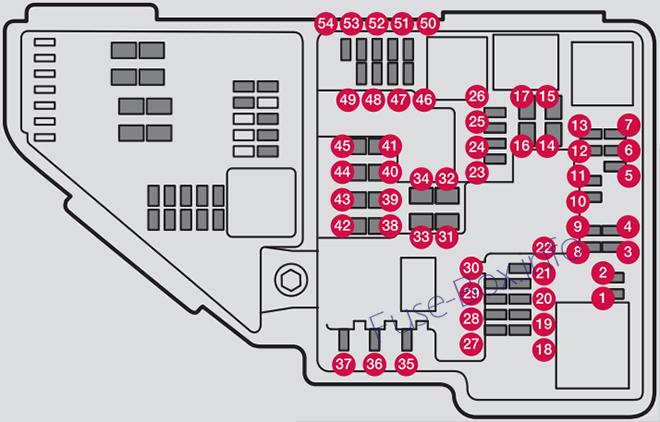
Engine compartment
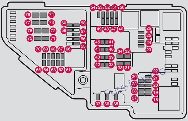
Assignment of fuses in the engine compartment (2016)
| № | Function | Amp |
|---|---|---|
| 18 | ||
| 19 | ||
| 20 | ||
| 21 | ||
| 22 | ||
| 23 | USB socket (option) | 5 |
| 24 | 12-volt socket in the cargo compartment | 15 |
| 25 | 12-volt socket on the rear side of the tunnel console | 15 |
| 26 | 12-volt socket in the front tunnel console | 15 |
| 27 | ||
| 28 | ||
| 29 | ||
| 30 | ||
| 31 | Heated windshield, driver side (option) | Shunt |
| 32 | Heated windshield, driver side (option) | 40 |
| 33 | Headlight washers (option) | 25 |
| 34 | Windshield washer | 25 |
| 35 | ||
| 36 | Horn | 20 |
| 37 | Alarm siren (option) | 5 |
| 38 | Brake system control module (valves, parking brake) | 40 |
| 39 | Windshield wipers | 30 |
| 40 | Tailgate window washer | 25 |
| 41 | Heated windshield, passenger side (option) | 40 |
| 42 | ||
| 43 | Brake system control module (ABS pump) | 40 |
| 44 | – | – |
| 45 | Heated windshield, passenger side (option) | Shunt |
| 46 | Feed when ignition is switched on to: engine control module, transmission components, electrical power steering, central electrical module; Brake system control module | 5 |
| 47 | ||
| 48 | Passenger side headlight | 7.5 |
| 49 | – | – |
| 50 | – | – |
| 51 | Battery connections control module | 5 |
| 52 | Air bags; Occupant Weight Sensor (OWS) | 5 |
| 53 | Driver side headlight | 7.5 |
| 54 | Accelerator pedal sensor | 5 |
| 55 | Transmission control module | 15 |
| 56 | Engine control module | 5 |
| 57 | – | – |
| 58 | – | – |
| 59 | – | – |
| 60 | – | – |
| 61 | Engine control module; Turbocharger valve | 20 |
| 62 | Solenoids; Valves; Engine cooling system thermostat | 10 |
| 63 | Vacuum regulators; Coolant fan relay winding; Valve | 7.5 |
| 64 | Spoiler shutter control module; Radiator shutter control module; Fuel leakage detection | 5 |
| 65 | ||
| 66 | Heated oxygen sensors (front and rear) | 15 |
| 67 | Oil pump solenoid; A/C magnetic coupling; heated oxygen sensor (center) | 15 |
| 68 | Crankcase ventilation heater | 7,5 |
| 69 | Engine control module | 20 |
| 70 | Ignition coil; Spark plugs | 15 |
| 71 | ||
| 72 | ||
| 73 | ||
| 74 | ||
| 75 | ||
| 76 | ||
| 77 | Starter motor | Shunt |
| 78 | Starter motor | Shunt |
Under the glove compartment
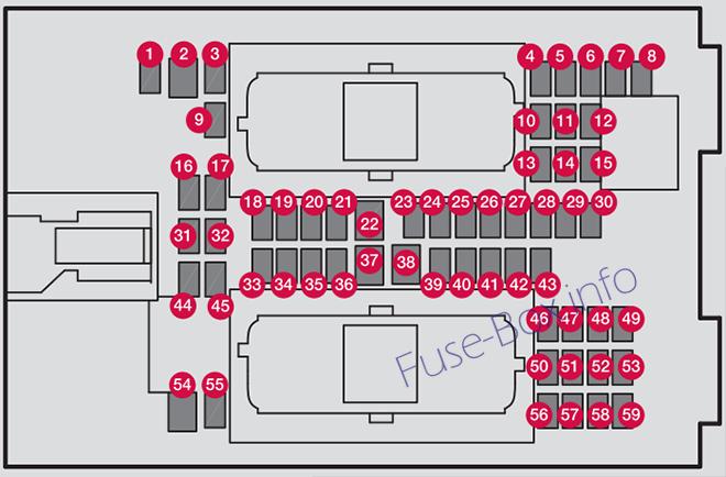
Assignment of fuses under the glove compartment (2016)
| № | Function | Amp |
|---|---|---|
| 1 | – | – |
| 2 | 110-volt socket | 30 |
| 3 | – | – |
| 4 | Alarm system movement sensor (option) | 5 |
| 5 | Media player | 5 |
| 6 | Instrument panel | 5 |
| 7 | Center console buttons | 5 |
| 8 | Sun sensor | 5 |
| 9 | ||
| 10 | ||
| 11 | Steering wheel module | 5 |
| 12 | Module for start knob and parking brake | 5 |
| 13 | Heated steering wheel module (option) | 15 |
| 14 | ||
| 15 | ||
| 16 | ||
| 17 | ||
| 18 | Climate system control module | 10 |
| 19 | – | – |
| 20 | On-board diagnostics (OBDII) | 5 |
| 21 | Center display | 5 |
| 22 | Climate system blower module (front) | 40 |
| 23 | – | – |
| 24 | Instrument lighting; Courtesy lighting; Rearview mirror auto-dim function; Rain and light sensor; Rear tunnel console keypad (option); Power front seats (option) | 7.5 |
| 25 | Control module for driver support functions | 5 |
| 26 | Panorama roof and sun shade (option) | 20 |
| 27 | Head-up display (option) | 5 |
| 28 | Courtesy lighting | 5 |
| 29 | – | – |
| 30 | Ceiling console display (seat belt reminder, front passenger side airbag indicator) | 5 |
| 31 | ||
| 32 | Humidity sensor | 5 |
| 33 | Rear passenger-side door module | 20 |
| 34 | Fuses in the cargo compartment | 10 |
| 35 | Internet connection control module; Volvo On Call control module | 5 |
| 36 | Rear driver-side door module | 20 |
| 37 | Infotainment control module (amplifier) | 40 |
| 38 | Climate system blower module (rear) | 40 |
| 39 | Multi-band antenna module | 5 |
| 40 | – | – |
| 41 | – | – |
| 42 | Tailgate window wiper | 15 |
| 43 | Fuel pump control module | 15 |
| 44 | – | – |
| 45 | – | – |
| 46 | Driver side seat heating (option) | 15 |
| 47 | Passenger side seat heating (option) | 15 |
| 48 | Coolant pump | 10 |
| 49 | – | – |
| 50 | Front driver-side door module | 20 |
| 51 | Active chassis (option) | 20 |
| 52 | – | – |
| 53 | Sensus control module | 10 |
| 54 | ||
| 55 | ||
| 56 | Front passenger-side door module | 20 |
| 57 | – | – |
| 58 | – | – |
| 59 | Circuit breaker for fuses 53 and 58 | 15 |
Cargo compartment
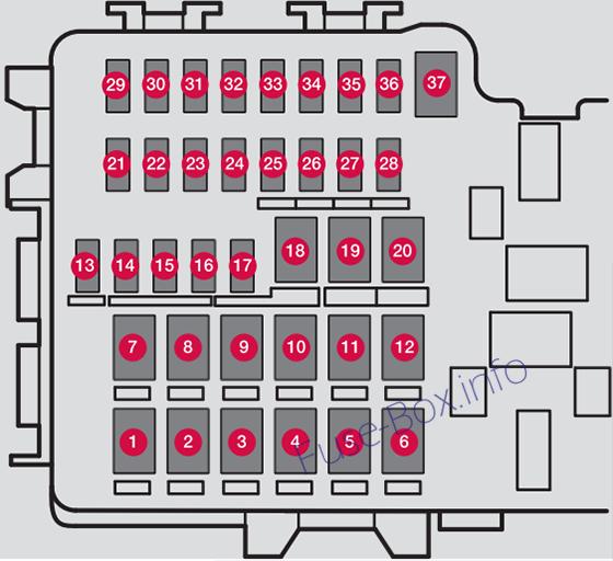
Assignment of fuses in the cargo compartment (2016)
| № | Function | Amp |
|---|---|---|
| 1 | Heated tailgate window | 30 |
| 2 | ||
| 3 | Pneumatic suspension compressor (option) | 40 |
| 4 | Heated rear seat (passenger side) (option) | 30 |
| 5 | – | – |
| 6 | Heated rear seat (driver side) (option) | 30 |
| 7 | ||
| 8 | ||
| 9 | Power tailgate (option) | 25 |
| 10 | Power passenger seat module (option) | 20 |
| 11 | Trailer hitch control module (option) | 40 |
| 12 | Seat belt tensioner module (passenger side) | 40 |
| 13 | Internal relay windings | 5 |
| 14 | – | – |
| 15 | Foot movement detection module for opening the power tailgate (option) | 5 |
| 16 | – | – |
| 17 | Folding third row seats backrest module (option) | 20 |
| 18 | Trailer hitch control module (option) | 25 |
| 19 | Power driver seat module (option) | 20 |
| 20 | Seat belt tensioner module (driver side) | 40 |
| 21 | Parking camera (option) | 5 |
| 22 | – | – |
| 23 | – | – |
| 24 | – | – |
| 25 | – | – |
| 26 | Airbag and seat belt tensioner modules | 5 |
| 27 | ||
| 28 | Heated rear seat (driver side) (option) | 15 |
| 29 | – | – |
| 30 | BLIS (option) | 5 |
| 31 | – | – |
| 32 | Seat belt tensioner modules | 5 |
| 33 | Emission system actuator | 5 |
| 34 | – | – |
| 35 | All Wheel Drive control module | 15 |
| 36 | Heated rear seat (passenger side) (option) | 15 |
| 37 |
2016 Twin-Engine
Engine compartment
Assignment of fuses in the engine compartment (2016 Twin-Engine)
| № | Function | Amp |
|---|---|---|
| 1 | Converter for controlling feed to the rear axle electric motor | 5 |
| 2 | – | – |
| 3 | – | – |
| 4 | Control module for engaging/ changing gears | 5 |
| 5 | High Voltage Coolant Heater control module | 5 |
| 6 | Control module for: charge module, heat exchanger cut-off valve, cut-off valve for coolant through the climate system | 5 |
| 7 | Hybrid battery control module for high-voltage converter for combined high-voltage genera-tor/starter motor with 500V-12V voltage converter | 5 |
| 8 | – | – |
| 9 | Converter for controlling feed to the rear axle electric motor | 10 |
| 10 | Hybrid battery control module for high-voltage converter for combined high-voltage genera-tor/starter motor with 500V-12V voltage converter | 10 |
| 11 | Charging module | 5 |
| 12 | Cut-off valve for hybrid battery coolant; coolant pump 1 for hybrid battery | 10 |
| 13 | Coolant pump for electric drive system | 10 |
| 14 | Hybrid component cooling fan | 25 |
| 15 | ||
| 16 | ||
| 17 | ||
| 18 | ||
| 19 | ||
| 20 | ||
| 21 | ||
| 22 | ||
| 23 | USB socket (option); USB-port (option) | 5 |
| 24 | 12-volt socket in the cargo compartment (option) | 15 |
| 25 | 12-volt socket on the rear side of the tunnel console | 15 |
| 26 | 12-volt socket in the front tunnel console | 15 |
| 27 | ||
| 28 | ||
| 29 | ||
| 30 | ||
| 31 | Heated windshield driver side (option) | Shunt |
| 32 | Heated windshield driver side (option) | 40 |
| 33 | Headlight washers (option) | 25 |
| 34 | Windshield washer | 25 |
| 35 | – | – |
| 36 | Horn | 20 |
| 37 | Alarm siren (option) | 5 |
| 38 | Brake system control module (valves, parking brake) | 40 |
| 39 | Windshield wipers | 30 |
| 40 | Tailgate window washer | 25 |
| 41 | Heated windshield, passenger side (option) | 40 |
| 42 | – | – |
| 43 | Brake system control module (ABS pump) | 40 |
| 44 | ||
| 45 | Heated windshield, passenger side (option) | Shunt |
| 46 | Feed when ignition is switched on to: engine control module, transmission components, electrical power steering, central electrical module; | 5 |
| 47 | Exterior vehicle sound (certain markets) | 5 |
| 48 | Passenger side headlight | 7,5 |
| 49 | ||
| 50 | ||
| 51 | ||
| 52 | Air bags; Occupant Weight Sensor (OWS) | 5 |
| 53 | Driver side headlight | 7,5 |
| 54 | Accelerator pedal sensor | 5 |
| 55 | Transmission control module; Gear selector control module | 15 |
| 56 | Engine control module | 5 |
| 57 | ||
| 58 | ||
| 59 | ||
| 60 | ||
| 61 | Engine control module; Turbocharger valve | 20 |
| 62 | Solenoids; Valves; Engine cooling system thermostat | 10 |
| 63 | Vacuum regulators; Coolant fan relay winding; Valve | 7,5 |
| 64 | Spoiler shutter control module; Radiator shutter control module; Fuel leakage detection | 5 |
| 65 | ||
| 66 | Heated oxygen sensors (front and rear) | 15 |
| 67 | Oil pump solenoid; A/C magnetic coupling; heated oxygen sensor (center) | 15 |
| 68 | – | – |
| 69 | Engine control module | 20 |
| 70 | Ignition coil; Spark plugs | 15 |
| 71 | ||
| 72 | ||
| 73 | Transmission oil pump control module | 30 |
| 74 | Vacuum pump control module | 40 |
| 75 | Transmission actuator | 25 |
| 76 | – | – |
| 77 | Starter motor | Shunt |
| 78 | Starter motor | Shunt |
Under the glove compartment
Assignment of fuses under the glove compartment (2016 Twin-Engine)
| № | Function | Amp |
|---|---|---|
| 1 | – | – |
| 2 | 110-volt socket | 30 |
| 3 | – | – |
| 4 | Alarm system movement sensor (option) | 5 |
| 5 | Media player | 5 |
| 6 | Instrument panel | 5 |
| 7 | Center console buttons | 5 |
| 8 | Sun sensor | 5 |
| 9 | ||
| 10 | ||
| 11 | Steering wheel module | 5 |
| 12 | Module for start knob and parking brake | 5 |
| 13 | Heated steering wheel module (option) | 15 |
| 14 | ||
| 15 | ||
| 16 | ||
| 17 | ||
| 18 | Climate system control module | 10 |
| 19 | – | – |
| 20 | On-board diagnostics (OBDII) | 5 |
| 21 | Center display | 5 |
| 22 | Climate system blower module (front) | 40 |
| 23 | – | – |
| 24 | Instrument lighting; Courtesy lighting; Rearview mirror auto-dim function; Rain and light sensor; Rear tunnel console keypad*; Power front seats (option) | 7.5 |
| 25 | Control module for driver support functions | 5 |
| 26 | Panorama roof and sun shade (option) | 20 |
| 27 | Head-up display (option) | 5 |
| 28 | Courtesy lighting | 5 |
| 29 | – | – |
| 30 | Ceiling console display (seat belt reminder, front passenger side airbag indicator) | 5 |
| 31 | ||
| 32 | Humidity sensor | 5 |
| 33 | Rear passenger-side door module | 20 |
| 34 | Fuses in the cargo compartment | 10 |
| 35 | Internet connection control module; Volvo On Call control module | 5 |
| 36 | Rear driver-side door module | 20 |
| 37 | Infotainment control module (amplifier) | 40 |
| 38 | Climate system blower module (rear) | 40 |
| 39 | Multi-band antenna module | 5 |
| 40 | Seat Comfort module/Massage | 5 |
| 41 | – | – |
| 42 | Tailgate window wiper | 15 |
| 43 | Fuel pump control module | 15 |
| 44 | Relay windings for engine compartment electrical module; Relay winding for transmission oil pump | 5 |
| 45 | – | – |
| 46 | Driver side seat heating (option) | 15 |
| 47 | Passenger side seat heating (option) | 15 |
| 48 | Coolant pump | 10 |
| 49 | – | – |
| 50 | Front driver-side door module | 20 |
| 51 | Active chassis (option) | 20 |
| 52 | – | – |
| 53 | Sensus control module | 10 |
| 54 | ||
| 55 | ||
| 56 | Front passenger-side door module | 20 |
| 57 | – | – |
| 58 | – | – |
| 59 | Circuit breaker for fuses 53 and 58 | 15 |
Cargo compartment
Assignment of fuses in the cargo compartment (2016 Twin-Engine)
| № | Function | Amp |
|---|---|---|
| 1 | Heated tailgate window | 30 |
| 2 | ||
| 3 | Pneumatic suspension compressor (option) | 40 |
| 4 | Heated rear seat (passenger side) (option) | 30 |
| 5 | – | – |
| 6 | Heated rear seat (driver side) (option) | 30 |
| 7 | ||
| 8 | ||
| 9 | Power tailgate (option) | 25 |
| 10 | Power passenger seat module (option) | 20 |
| 11 | Trailer hitch control module (option) | 40 |
| 12 | Seat belt tensioner module (passenger side) | 40 |
| 13 | Internal relay windings | 5 |
| 14 | – | – |
| 15 | Foot movement detection module for opening the power tailgate (option) | 5 |
| 16 | – | – |
| 17 | Folding third row seats backrest module (option) | 20 |
| 18 | Trailer hitch control module (option) | 25 |
| 19 | Power driver seat module (option) | 20 |
| 20 | Seat belt tensioner module (driver side) | 40 |
| 21 | Parking camera (option) | 5 |
| 22 | – | – |
| 23 | – | – |
| 24 | – | – |
| 25 | Feed when ignition is switched on | 10 |
| 26 | Airbag and seat belt tensioner modules | 5 |
| 27 | ||
| 28 | Heated rear seat (driver side) (option) | 15 |
| 29 | – | – |
| 30 | BLIS (option) | 5 |
| 31 | – | – |
| 32 | Seat belt tensioner modules | 5 |
| 33 | Emission system actuator | 5 |
| 34 | – | – |
| 35 | – | – |
| 36 | Heated rear seat (passenger side) (option) | 15 |
| 37 |
2017
Engine compartment
Assignment of fuses in the engine compartment (2017)
| № | Function | Amp |
|---|---|---|
| 18 | – | – |
| 19 | – | – |
| 20 | – | – |
| 21 | – | – |
| 22 | – | – |
| 23 | Front USB socket (option) | 5 |
| 24 | 12-volt socket in the front tunnel console | 15 |
| 25 | 12-volt socket on the rear side of the tunnel console; 12-volt socket in the tunnel console between the rear seats | 15 |
| 26 | 12-volt socket in the cargo compartment | 15 |
| 27 | ||
| 28 | ||
| 29 | ||
| 30 | ||
| 31 | Heated windshield, driver side (option) | Shunt |
| 32 | Heated windshield, driver side (option) | 40 |
| 33 | Headlight washers (option) | 25 |
| 34 | Windshield washer | 25 |
| 35 | – | – |
| 36 | Horn | 20 |
| 37 | Alarm siren (option) | 5 |
| 38 | Brake system control module (valves, parking brake) | 40 |
| 39 | Windshield wipers | 30 |
| 40 | Rear window washer | 25 |
| 41 | Heated windshield, passenger side (option) | 40 |
| 42 | – | – |
| 43 | Brake system control module (ABS pump) | 40 |
| 44 | ||
| 45 | Heated windshield, passenger side (option) | Shunt |
| 46 | Feed when ignition is switched on to: engine control module, transmission components, electrical power steering, central electrical module; Brake system control module | 5 |
| 47 | – | – |
| 48 | Passenger side headlight | 7.5 |
| 49 | ||
| 50 | ||
| 51 | Battery connections control module | 5 |
| 52 | Air bags; Occupant Weight Sensor (OWS) | 5 |
| 53 | Driver side headlight | 7.5 |
| 54 | Accelerator pedal sensor | 5 |
| 55 | Transmission control module | 15 |
| 56 | Engine control module | 5 |
| 57 | ||
| 58 | ||
| 59 | ||
| 60 | ||
| 61 | Engine control module; actuator; Turbocharger valve | 20 |
| 62 | Solenoids; Valves; Engine cooling system thermostat | 10 |
| 63 | Vacuum regulators; Valve | 7.5 |
| 64 | Spoiler shutter control module; Radiator shutter control module; Fuel leakage detection | 5 |
| 65 | ||
| 66 | Heated oxygen sensors (front and rear) | 15 |
| 67 | Oil pump solenoid; A/C magnetic coupling; heated oxygen sensor (center) | 15 |
| 68 | – | – |
| 69 | Engine control module | 20 |
| 70 | Ignition coil; Spark plugs | 15 |
| 71 | ||
| 72 | ||
| 73 | ||
| 74 | ||
| 75 | ||
| 76 | ||
| 77 | Starter motor | Shunt |
| 78 | Starter motor | 40 |
Under the glove compartment
Assignment of fuses under the glove compartment (2017)
| № | Function | Amp |
|---|---|---|
| 1 | – | – |
| 2 | 120-volt socket on the rear side of the tunnel console (option) | 30 |
| 3 | – | – |
| 4 | Alarm system movement sensor (option) | 5 |
| 5 | Media player | 5 |
| 6 | Instrument panel | 5 |
| 7 | Center console buttons | 5 |
| 8 | Sun sensor | 5 |
| 9 | ||
| 10 | ||
| 11 | Steering wheel module | 5 |
| 12 | Module for start knob and parking brake | 5 |
| 13 | Heated steering wheel module (option) | 15 |
| 14 | ||
| 15 | ||
| 16 | ||
| 17 | ||
| 18 | Climate system control module | 10 |
| 19 | – | – |
| 20 | On-board diagnostics (OBDII) | 10 |
| 21 | Center display | 5 |
| 22 | Climate system blower module (front) | 40 |
| 23 | – | – |
| 24 | Instrument lighting; Courtesy lighting; Rearview mirror auto-dim function; Rain and light sensor; Rear tunnel console keypad*; Power front seats (option) | 7.5 |
| 25 | Control module for driver support functions | 5 |
| 26 | Panorama roof and sun shade (option) | 20 |
| 27 | Head-up display (option) | 5 |
| 28 | Courtesy lighting | 5 |
| 29 | – | – |
| 30 | Ceiling console display (seat belt reminder, front passenger side airbag indicator) | 5 |
| 31 | ||
| 32 | Humidity sensor | 5 |
| 33 | Rear passenger-side door module | 20 |
| 34 | Fuses in the cargo compartment | 10 |
| 35 | Internet connection control module; Volvo On Call control module | 5 |
| 36 | Rear driver-side door module | 20 |
| 37 | Infotainment control module (amplifier) | 40 |
| 38 | Climate system blower module (rear) | 40 |
| 39 | Multi-band antenna module | 5 |
| 40 | Front seat massage function | 5 |
| 41 | – | – |
| 42 | Tailgate window wiper | 15 |
| 43 | Fuel pump control module | 15 |
| 44 | – | – |
| 45 | – | – |
| 46 | Driver side seat heating (option) | 15 |
| 47 | Passenger side seat heating (option) | 15 |
| 48 | Coolant pump | 10 |
| 49 | – | – |
| 50 | Front driver-side door module | 20 |
| 51 | Active chassis (option) | 20 |
| 52 | – | – |
| 53 | Sensus control module | 10 |
| 54 | ||
| 55 | ||
| 56 | Front passenger-side door module | 20 |
| 57 | – | – |
| 58 | – | – |
| 59 | Circuit breaker for fuses 53 and 58 | 15 |
Cargo compartment
Assignment of fuses in the cargo compartment (2017)
| № | Function | Amp |
|---|---|---|
| 1 | Heated tailgate window | 30 |
| 2 | ||
| 3 | Pneumatic suspension compressor (option) | 40 |
| 4 | Heated rear seat (passenger side) (option) | 30 |
| 5 | – | – |
| 6 | Heated rear seat (driver side) (option) | 30 |
| 7 | ||
| 8 | ||
| 9 | Power tailgate (option) | 25 |
| 10 | Power passenger seat module (option) | 20 |
| 11 | Trailer hitch control module (option) | 40 |
| 12 | Seat belt tensioner module (passenger side) | 40 |
| 13 | Internal relay windings | 5 |
| 14 | – | – |
| 15 | Foot movement detection module for opening the power tailgate (option) | 5 |
| 16 | – | – |
| 17 | Folding third row seats backrest module (option) | 20 |
| 18 | Trailer hitch control module (option) | 25 |
| 19 | Power driver seat* module | 20 |
| 20 | Seat belt tensioner module (driver side) | 40 |
| 21 | Parking camera (option) | 5 |
| 22 | – | – |
| 23 | – | – |
| 24 | – | – |
| 25 | – | – |
| 26 | Airbag and seat belt tensioner modules | 5 |
| 27 | ||
| 28 | Heated rear seat (driver side) (option) | 15 |
| 29 | – | – |
| 30 | BLIS (option) | 5 |
| 31 | – | – |
| 32 | Seat belt tensioner modules | 5 |
| 33 | Emission system actuator | 5 |
| 34 | – | – |
| 35 | All Wheel Drive control module | 15 |
| 36 | Heated rear seat (passenger side) (option) | 15 |
| 37 |
2017 Twin-Engine
Engine compartment
Assignment of fuses in the engine compartment (2017 Twin-Engine)
| № | Function | Amp |
|---|---|---|
| 1 | Converter for controlling feed to the rear axle electric motor | 5 |
| 2 | – | – |
| 3 | – | – |
| 4 | Control module for engaging/ changing gears | 5 |
| 5 | High Voltage Coolant Heater control module | 5 |
| 6 | Control module for: charge module, heat exchanger cut-off valve, cut-off valve for coolant through the climate system | 5 |
| 7 | Hybrid battery control module for high-voltage converter for combined high-voltage genera-tor/starter motor with 500V-12V voltage converter | 5 |
| 8 | – | – |
| 9 | Converter for controlling feed to the rear axle electric motor | 10 |
| 10 | Hybrid battery control module for high-voltage converter for combined high-voltage genera-tor/starter motor with 500V-12V voltage converter | 10 |
| 11 | Charging module | 5 |
| 12 | Cut-off valve for hybrid battery coolant; coolant pump 1 for hybrid battery | 10 |
| 13 | Coolant pump for electric drive system | 10 |
| 14 | Hybrid component cooling fan | 25 |
| 15 | ||
| 16 | ||
| 17 | ||
| 18 | ||
| 19 | ||
| 20 | ||
| 21 | ||
| 22 | ||
| 23 | Front USB socket (option) | 5 |
| 24 | 12-volt socket in the front tunnel console | 15 |
| 25 | 12-volt socket on the rear side of the tunnel console (Not XC90 Excellence); 12-volt socket in the tunnel console between the rear seats (XC90 Excellence) | 15 |
| 26 | 12-volt socket in the cargo compartment; USB sockets for iPad holdersB | 15 |
| 27 | ||
| 28 | ||
| 29 | ||
| 30 | ||
| 31 | Heated windshield driver side (option) | Shunt |
| 32 | Heated windshield driver side (option) | 40 |
| 33 | Headlight washers (option) | 25 |
| 34 | Windshield washer | 25 |
| 35 | – | – |
| 36 | Horn | 20 |
| 37 | Alarm siren (option) | 5 |
| 38 | Brake system control module (valves, parking brake) | 40 |
| 39 | Windshield wipers | 30 |
| 40 | Tailgate window washer | 25 |
| 41 | Heated windshield, passenger side (option) | 40 |
| 42 | – | – |
| 43 | Brake system control module (ABS pump) | 40 |
| 44 | ||
| 45 | Heated windshield, passenger side (option) | Shunt |
| 46 | Feed when ignition is switched on to: engine control module, transmission components, electrical power steering, central electrical module; | 5 |
| 47 | Exterior vehicle sound (certain markets) | 5 |
| 48 | Passenger side headlight | 7,5 |
| 49 | ||
| 50 | ||
| 51 | ||
| 52 | Air bags; Occupant Weight Sensor (OWS) | 5 |
| 53 | Driver side headlight | 7,5 |
| 54 | Accelerator pedal sensor | 5 |
| 55 | Transmission control module; Gear selector control module | 15 |
| 56 | Engine control module | 5 |
| 57 | ||
| 58 | ||
| 59 | ||
| 60 | ||
| 61 | Engine control module; Turbocharger valve | 20 |
| 62 | Solenoids; Valves; Engine cooling system thermostat | 10 |
| 63 | Vacuum regulators; Coolant fan relay winding; Valve | 7,5 |
| 64 | Spoiler shutter control module; Radiator shutter control module; Fuel leakage detection | 5 |
| 65 | ||
| 66 | Heated oxygen sensors (front and rear) | 15 |
| 67 | Oil pump solenoid; A/C magnetic coupling; heated oxygen sensor (center) | 15 |
| 68 | – | – |
| 69 | Engine control module | 20 |
| 70 | Ignition coil; Spark plugs | 15 |
| 71 | ||
| 72 | ||
| 73 | Transmission oil pump control module | 30 |
| 74 | Vacuum pump control module | 40 |
| 75 | Transmission actuator | 25 |
| 76 | – | – |
| 77 | – | – |
| 78 | – | – |
Under the glove compartment
Assignment of fuses under the glove compartment (2017 Twin-Engine)
| № | Function | Amp |
|---|---|---|
| 1 | – | – |
| 2 | 120-volt socket on the rear side of the tunnel console (option) | 30 |
| 3 | – | – |
| 4 | Alarm system movement sensor (option) | 5 |
| 5 | Media player | 5 |
| 6 | Instrument panel | 5 |
| 7 | Center console buttons | 5 |
| 8 | Sun sensor | 5 |
| 9 | ||
| 10 | ||
| 11 | Steering wheel module | 5 |
| 12 | Module for start knob and parking brake | 5 |
| 13 | Heated steering wheel module (option) | 15 |
| 14 | ||
| 15 | ||
| 16 | ||
| 17 | ||
| 18 | Climate system control module | 10 |
| 19 | – | – |
| 20 | On-board diagnostics (OBDII) | 10 |
| 21 | Center display | 5 |
| 22 | Climate system blower module (front) | 40 |
| 23 | – | – |
| 24 | Instrument lighting; Courtesy lighting; Rearview mirror auto-dim function; Rain and light sensor; Rear tunnel console keypad (option); Power front seats (option); Instrument lighting; Courtesy lighting; Rearview mirror auto-dim function; Rain and light sensor; Rear tunnel console keypad (option) (Not Excellence); Power front seats (option); Power rear seats (Excellence only); Display for rear seat convenience functions (option); Rear seat massage function (option) | 7.5 |
| 25 | Control module for driver support functions | 5 |
| 26 | Panorama roof and sun shade (option) | 20 |
| 27 | Head-up display (option) | 5 |
| 28 | Courtesy lighting | 5 |
| 29 | – | – |
| 30 | Ceiling console display (seat belt reminder, front passenger side airbag indicator) | 5 |
| 31 | ||
| 32 | Humidity sensor | 5 |
| 33 | Rear passenger-side door module | 20 |
| 34 | Fuses in the cargo compartment | 10 |
| 35 | Internet connection control module; Volvo On Call control module | 5 |
| 36 | Rear driver-side door module | 20 |
| 37 | Infotainment control module (amplifier) | 40 |
| 38 | Climate system blower module (rear) | 40 |
| 39 | Multi-band antenna module | 5 |
| 40 | Front seat massage function | 5 |
| 41 | – | – |
| 42 | Tailgate window wiper | 15 |
| 43 | Fuel pump control module | 15 |
| 44 | Relay windings for engine compartment electrical module; Relay winding for transmission oil pump | 5 |
| 45 | – | – |
| 46 | Driver side seat heating (option) | 15 |
| 47 | Passenger side seat heating (option) | 15 |
| 48 | Coolant pump | 10 |
| 49 | – | – |
| 50 | Front driver-side door module | 20 |
| 51 | Active chassis (option) | 20 |
| 52 | – | – |
| 53 | Sensus control module | 10 |
| 54 | ||
| 55 | ||
| 56 | Front passenger-side door module | 20 |
| 57 | Display for rear seat convenience functions (Excellence only) | 5 |
| 58 | – | – |
| 59 | Circuit breaker for fuses 53 and 58 | 15 |
Cargo compartment
Assignment of fuses in the cargo compartment (2017 Twin-Engine)
| № | Function | Amp |
|---|---|---|
| 1 | Heated tailgate window | 30 |
| 2 | Power rear seat (driver side) (XC90 Excellence) | 20 |
| 3 | Pneumatic suspension compressor (option) | 40 |
| 4 | Heated rear seat (passenger side) (option) | 30 |
| 5 | – | – |
| 6 | Heated rear seat (driver side) (option) | 30 |
| 7 | Power rear seat (passenger side) (XC90 Excellence) | 20 |
| 8 | ||
| 9 | Power tailgate (option) | 25 |
| 10 | Power passenger seat module (option) | 20 |
| 11 | Trailer hitch control module (option) | 40 |
| 12 | Seat belt tensioner module (passenger side) | 40 |
| 13 | Internal relay windings | 5 |
| 14 | – | – |
| 15 | Foot movement detection module for opening the power tailgate (option) | 5 |
| 16 | – | – |
| 17 | Folding third row seats backrest module (option) | 20 |
| 18 | Trailer hitch control module (option) | 25 |
| 19 | Power driver seat module (option) | 20 |
| 20 | Seat belt tensioner module (driver side) | 40 |
| 21 | Parking camera (option) | 5 |
| 22 | – | – |
| 23 | – | – |
| 24 | Ionic air cleaner (XC90 Excellence) | 5 |
| 25 | Feed when ignition is switched on. | 10 |
| 26 | Airbag and seat belt tensioner modules | 5 |
| 27 | Cooler; heated/cooled cup holder (rear) (XC90 Excellence) | 10 |
| 28 | Heated rear seat (driver side) (option) | 15 |
| 29 | – | – |
| 30 | BLIS (option) | 5 |
| 31 | – | – |
| 32 | Seat belt tensioner modules | 5 |
| 33 | Emission system actuator | 5 |
| 34 | – | – |
| 35 | – | – |
| 36 | Heated rear seat (passenger side) (option) | 15 |
| 37 |
2018
Engine compartment
Assignment of fuses in the engine compartment (2018)
| № | Function | Amp |
|---|---|---|
| 1 | – | – |
| 2 | – | – |
| 3 | – | – |
| 4 | Ignition coils (petrol); Spark plugs (petrol) | 15 |
| 5 | Solenoid for engine oil pump; Solenoid clutch A/C; Lambda sond, centre (petrol); Lambda sond, rear (diesel) | 15 |
| 6 | Vacuum regulators; Valve; Valve for output pulse (diesel) | 7.5 |
| 7 | Engine control module; Actuator; Throttle unit; EGR valve (diesel); Position sensor for turbo (diesel); Valve for turbocharger (petrol) | 20 |
| 8 | Engine Control Module (ECM) | 5 |
| 9 | ||
| 10 | Solenoids (petrol); Valve; Thermostat for engine cooling system (petrol); EGR cooling pump (diesel); Glow control module (diesel) | 10 |
| 11 | Control module for spoiler roller cover; Control module for radiator roller cover; Relay coils for output pulse (diesel) | 5 |
| 12 | Lambda-sond, front; Lambda-sond, rear (petrol) | 15 |
| 13 | Engine Control Module (ECM) | 20 |
| 14 | Starter motor | 40 |
| 15 | Starter motor | Shunt |
| 16 | Fuel filter heater (diesel) | 30 |
| 17 | ||
| 18 | ||
| 19 | ||
| 20 | ||
| 21 | ||
| 22 | ||
| 23 | ||
| 24 | 12 V socket in tunnel console, front | 15 |
| 25 | 12 V socket in tunnel console, by legroom for second seat row | 15 |
| 26 | 12 V socket in cargo area (option) | 15 |
| 27 | ||
| 28 | ||
| 29 | ||
| 30 | ||
| 31 | Heated windscreen left-hand side (option) | Shunt |
| 32 | Heated windscreen left-hand side (option) | 40 |
| 33 | Headlamp washers (option) | 25 |
| 34 | Windscreen washers | 25 |
| 35 | Transmission control module | 15 |
| 36 | Horn | 20 |
| 37 | Siren (option) | 5 |
| 38 | Control module for brake system (valves, parking brake) | 40 |
| 39 | Windscreen wipers | 30 |
| 40 | Rear window washer | 25 |
| 41 | Heated windscreen right-hand side (option) | 40 |
| 42 | 20 | |
| 43 | Control unit for brake system (ABS pump) | 40 |
| 44 | ||
| 45 | Heated windscreen right-hand side (option) | Shunt |
| 46 | Supplied when the ignition is switched on: Engine control module; Transmission components; Electric steeringlservo; Central electronic module; Control module for brake system | 5 |
| 47 | – | – |
| 48 | Right-hand headlamp | 7.5 |
| 48 | Right-hand headlamp, certain variants of LED | 7.5 |
| 49 | ||
| 50 | ||
| 51 | Module for controlling battery engagement | 5 |
| 52 | Airbags | 5 |
| 53 | Left-hand headlamp | 7.5 |
| 53 | Left-hand headlamp, certain variants of LED | 7.5 |
| 54 | Accelerator pedal sensor | 5 |
Under the glove compartment
Assignment of fuses under the glove compartment (2018)
| № | Function | Amp |
|---|---|---|
| 1 | – | – |
| 2 | 230 V socket in tunnel console, by legroom for second seat row (option) | 30 |
| 3 | – | – |
| 4 | Movement detector (option) | 5 |
| 5 | Media player | 5 |
| 6 | Driver display | 5 |
| 7 | Keypad in centre console | 5 |
| 8 | Sun sensor | 5 |
| 9 | – | – |
| 10 | – | – |
| 11 | Steering wheel module | 5 |
| 12 | Module for start knob and for parking brake control | 5 |
| 13 | Steering wheel module for heated steering wheel (option) | 15 |
| 14 | ||
| 15 | ||
| 16 | ||
| 17 | ||
| 18 | Control module for climate control system | 10 |
| 19 | Steering lock | 7.5 |
| 20 | Diagnostic socket OBDII | 10 |
| 21 | Centre display | 5 |
| 22 | Fan module for climate control system, front | 40 |
| 23 | USB HUB | 5 |
| 24 | Controls lighting; Interior lighting; Dimming of interior rearview mirror (option); Rain and light sensor (option); Keypad in tunnel console, by legroom for rear seat (option); Power front seats (option); Control panels in rear doors | 7.5 |
| 25 | Control module for driver support functions | 5 |
| 26 | Panorama roof with sun blind (option) | 20 |
| 27 | Head-up display (option) | 5 |
| 28 | Passenger compartment lighting | 5 |
| 29 | ||
| 30 | Display in roof console (Seatbelt reminder/lndicator for airbag on the front passenger seat) | 5 |
| 31 | – | – |
| 32 | Humidity sensor | 5 |
| 33 | Door module in right-hand rear door | 20 |
| 34 | Fuses in cargo area | 10 |
| 35 | Control module for online connected car: Control module for Volvo On Call | 5 |
| 36 | Door module in left-hand rear door | 20 |
| 37 | Audio control module (amplifier) (certain variants) | 40 |
| 38 | Fan module for climate control system, rear (option) | 40 |
| 39 | Module for multi-band antenna | 5 |
| 40 | Modules for seat comfort (massage) front (option) | 5 |
| 41 | – | – |
| 42 | Rear window wiper | 15 |
| 43 | Control module for fuel pump | 15 |
| 44 | – | – |
| 45 | – | – |
| 46 | Seat heating, driver’s side front | 15 |
| 47 | Seat heating, passenger side front | 15 |
| 48 | Coolant pump | 10 |
| 49 | ||
| 50 | Door module in left-hand front door | 20 |
| 51 | Control module for suspension (active chassis) (option) | 20 |
| 52 | – | – |
| 53 | Sensus control module | 10 |
| 54 | – | – |
| 55 | – | – |
| 56 | Door module in right-hand front door | 20 |
| 57 | – | – |
| 58 | TV (option) (certain markets) | 5 |
| 59 | Primary fuse for fuses 53 and 58 | 15 |
Cargo compartment
Assignment of fuses in the cargo compartment (2018)
| № | Function | Amp |
|---|---|---|
| 1 | Rear window defroster | 30 |
| 2 | – | – |
| 3 | Compressor for air suspension (option) | 40 |
| 4 | Electric additional heaters right-hand side rear (option) | 30 |
| 5 | ||
| 6 | Electric additional heaters left-hand side rear (option) | 30 |
| 7 | – | – |
| 8 | Control module for reduction of nitrous oxides (diesel) | 30 |
| 9 | Power operated tailgate (option) | 25 |
| 10 | Electrically operated front passenger seat (option) | 20 |
| 11 | Towbar control module (option) | 40 |
| 12 | Seatbelt pretensioner module, right-hand side | 40 |
| 13 | Internal relay coils | 5 |
| 14 | Control module for reduction of nitrous oxides (diesel) | 15 |
| 15 | Module for detecting foot movement (option) (for opening the power operated tailgate) | 5 |
| 16 | Alcohol lock | 5 |
| 17 | Module for lowering the backrest in the third seat row (option) | 20 |
| 18 | Towbar control module (option) | 25 |
| 19 | Power driver seat (option) | 20 |
| 20 | Seatbelt pretensioner module, left-hand side | 40 |
| 21 | Parking camera (option) | 5 |
| 22 | ||
| 23 | ||
| 24 | ||
| 25 | ||
| 26 | Control module for airbags and seatbelt tensioners | 5 |
| 27 | – | – |
| 28 | Seat heating left-hand side rear (option) | 15 |
| 29 | – | – |
| 30 | Blind Spot Information (BLIS) (option): control module, exterior reversing sound | 5 |
| 31 | ||
| 32 | Seatbelt pretensioner modules | 5 |
| 33 | Actuator for exhaust gases (petrol, certain engine variants) | 5 |
| 34 | – | – |
| 35 | All Wheel Drive (AWD) control module (option) | 15 |
| 36 | Seat heating right-hand side rear (option) | 15 |
| 37 | – | – |
2019
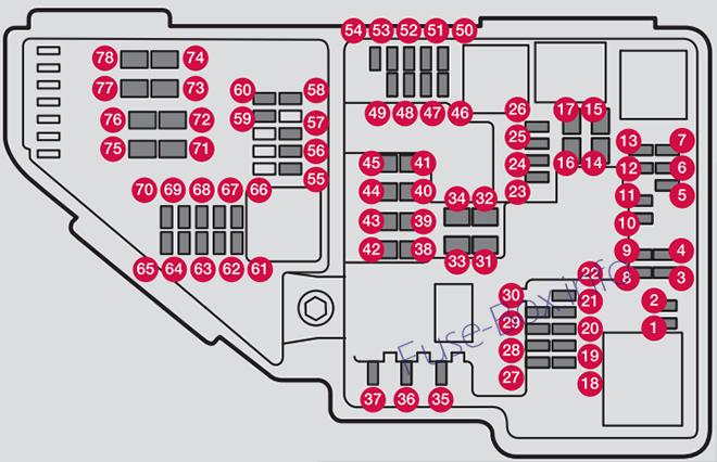
Engine compartment
Assignment of fuses in the engine compartment (2019)
| № | Ampere | Function |
|---|---|---|
| 1 | – | Not Used |
| 2 | – | Not Used |
| 3 | – | Not Used |
| 4 | 15 | Ignition coils (gasoline); spark plugs (gasoline) |
| 5 | 15 | Oil pump solenoid; A/C magnetic coupling; heated oxygen sensor, center (gasoline); heated oxygen sensor, rear (diesel) |
| 6 | 7.5 | Vacuum regulators; valve; valve for power pulse (diesel) |
| 7 | 20 | Engine control module; actuator; throttle unit; EGR valve (diesel); turbo position sensor (diesel); turbocharger valve (gasoline) |
| 8 | 5 | Engine control module |
| 9 | – | Not Used |
| 10 | 10 | Solenoids (gasoline); valve; Engine cooling system thermostat (gasoline); EGR cooling pump (diesel); glow control module (diesel) |
| 11 | 5 | Spoiler shutter control module; Radiator shutter control module; Relay windings for power pulse (diesel) |
| 12 | – | Not Used |
| 13 | 20 | Engine control module |
| 14 | 40 | Starter motor |
| 15 | Shunt | Starter motor |
| 16 | 30 | Fuel filter heater (diesel) |
| 17 | – | Not Used |
| 18 | – | Not Used |
| 19 | – | Not Used |
| 20 | – | Not Used |
| 21 | – | Not Used |
| 22 | – | Not Used |
| 23 | – | Not Used |
| 24 | 15 | 12 V outlet in tunnel console, front |
| 25 | 15 | 12 V outlet in tunnel console between rear seats |
| 26 | 15 | 12 V outlet in trunk/cargo compartment |
| 27 | – | Not Used |
| 28 | 15 | Left-side headlight, some models with LED |
| 29 | 15 | Right-side headlight, some models with LED |
| 30 | – | Not Used |
| 31 | Shunt | Heated windshield, left side |
| 32 | 40 | Heated windshield, left side |
| 33 | 25 | Headlight washers |
| 34 | 25 | Windshield washer |
| 35 | 15 | Transmission control module |
| 36 | 20 | Horn |
| 37 | 5 | Alarm siren |
| 38 | 40 | Brake system control module (valves, parking brake) |
| 39 | 30 | Wipers |
| 40 | 25 | Rear window washer |
| 41 | 40 | Heated windshield, right side |
| 42 | 20 | Parking heater |
| 43 | 40 | Brake system control module (ABS pump) |
| 44 | – | Not Used |
| 45 | Shunt | Heated windshield, right side |
| 46 | 5 | Fed when ignition is on: engine control module, transmission components, electrical power steering, central electrical module, brake system control module |
| 47 | – | Not Used |
| 48 | 7.5 | Right-side headlight |
| 48 | 15 | Right-side headlight, some models with LED |
| 49 | – | Not Used |
| 50 | – | Not Used |
| 51 | 5 | Battery connection control module |
| 52 | 5 | Airbags |
| 53 | 7.5 | Left-side headlight |
| 53 | 15 | Left-side headlight, some models with LED |
| 54 | 5 | Accelerator pedal sensor |
Engine compartment (Twin-engine)
Assignment of fuses in the engine compartment, Twin-engine (2019)
| № | Ampere | Function |
|---|---|---|
| 1 | – | Not Used |
| 2 | – | Not Used |
| 3 | – | Not Used |
| 4 | 5 | Control module for actuator for engaging/changing gears, automatic transmission |
| 5 | 5 | High-voltage coolant heater control module |
| 6 | 5 | Control module for A/C; heat exchanger cut-off valve; cutoff valve for coolant through the climate system |
| 7 | 5 | Hybrid battery control module; high-voltage converter for combined high-voltage gener-ator/starter motor with 500V-12 V voltage converter |
| 8 | – | Not Used |
| 9 | 10 | Converter for controlling feed to rear axle electric motor |
| 10 | 10 | Hybrid battery control module; high-voltage converter for combined high-voltage gener-ator/starter motor with 500 V-12 V voltage converter |
| 11 | 5 | Charge module |
| 12 | 10 | Cut-off valve for hybrid battery coolant; coolant pump 1 for hybrid battery |
| 13 | 10 | Coolant pump for electric drive system |
| 14 | 25 | Hybrid component cooling fan |
| 15 | – | Not Used |
| 16 | – | Not Used |
| 17 | – | Not Used |
| 18 | – | Not Used |
| 19 | – | Not Used |
| 20 | – | Not Used |
| 21 | – | Not Used |
| 22 | – | Not Used |
| 23 | – | Not Used |
| 24 | 15 | 12 V outlet in tunnel console, front |
| 25 | 15 | Not Excellence: 12 V outlet in tunnel console between second-row seats Excellence: 12 V outlet in tunnel console, between rear seats; USB ports in tunnel console between rear seats |
| 26 | 15 | 12 V outlet in trunk/cargo compartment USB ports for iPad holders |
| 27 | – | Not Used |
| 28 | – | Not Used |
| 29 | – | Not Used |
| 30 | – | Not Used |
| 31 | Shunt | Heated windshield, left side |
| 32 | 40 | Heated windshield, left side |
| 33 | 25 | Headlight washers |
| 34 | 25 | Windshield washer |
| 35 | – | Not Used |
| 36 | 20 | Horn |
| 37 | 5 | Alarm siren |
| 38 | 40 | Brake system control module (valves, parking brake) |
| 39 | 30 | Wipers |
| 40 | 25 | Rear window washer |
| 41 | 40 | Heated windshield, right side |
| 42 | 20 | Parking heater |
| 43 | 40 | Brake system control module (ABS pump) |
| 44 | – | Not Used |
| 45 | Shunt | Heated windshield, right side |
| 46 | 5 | Fed when ignition is on: Engine control module; transmission components, electrical power steering, central electrical module |
| 47 | 5 | Exterior vehicle sound (certain markets) |
| 48 | 7.5 | Right-side headlight |
| 48 | 15 | Right-side headlight, some models with LED |
| 49 | – | Not Used |
| 50 | – | Not Used |
| 51 | – | Not Used |
| 52 | 5 | Airbags |
| 53 | 7.5 | Left-side headlight |
| 53 | 15 | Left-side headlight, some models with LED |
| 54 | 5 | Accelerator pedal sensor |
| 55 | 15 | Transmission control module; gear selector control module |
| 56 | 5 | Engine control module |
| 57 | – | Not Used |
| 58 | – | Not Used |
| 59 | – | Not Used |
| 60 | – | Not Used |
| 61 | 20 | Engine control module; actuator; throttle unit; turbo-charger valve |
| 62 | 10 | Solenoids; valve; engine cooling system thermostat |
| 63 | 7.5 | Vacuum regulators; valve |
| 64 | 5 | Spoiler shutter control module; radiator shutter control module |
| 65 | – | Not Used |
| 66 | 15 | Heated oxygen sensor, front; heated oxygen sensor, rear |
| 67 | 15 | Oil pump solenoid; A/C magnetic coupling; heated oxygen sensor (center) |
| 68 | – | Not Used |
| 69 | 20 | Engine control module |
| 70 | 15 | Ignition coils; spark plugs |
| 71 | – | Not Used |
| 72 | – | Not Used |
| 73 | 30 | Transmission oil pump control module |
| 74 | 40 | Vacuum pump control module |
| 75 | 25 | Transmission actuator |
| 76 | – | Not Used |
| 77 | – | Not Used |
| 78 | – | Not Used |
Under the glovebox
Assignment of fuses under the glovebox (2019)
| № | Ampere | Function |
|---|---|---|
| 1 | – | Not Used |
| 2 | 30 | Electrical outlet in tunnel console between rear seats |
| 3 | – | Not Used |
| 4 | 5 | Movement sensor |
| 5 | 5 | Media player |
| 6 | 5 | Instrument panel |
| 7 | 5 | Center console buttons |
| 8 | 5 | Sun sensor |
| 9 | 20 | Sensus control module |
| 10 | – | Not Used |
| 11 | 5 | Steering wheel module |
| 12 | 5 | Module for start knob and parking brake controls |
| 13 | 15 | Heated steering wheel module |
| 14 | – | Not Used |
| 15 | – | Not Used |
| 16 | – | Not Used |
| 17 | – | Not Used |
| 18 | 10 | Climate system control module |
| 19 | – | Not Used |
| 20 | 10 | Data link connector OBD-II |
| 21 | 5 | Center display |
| 22 | 40 | Climate system blower module (front) |
| 23 | 5 | USB HUB |
| 24 | 7.5 | Instrument lighting; Interior lighting; Rearview mirror auto-dim function; Rain and light sensors; Rear tunnel console keypad, rear seat; Power front seats; Rear door control panels; Climate system blower module left/right
Power rear seats; Display for rear seat convenience functions; Rear seat massage function |
| 25 | 5 | Control module for driver support functions |
| 26 | 20 | Panoramic roof with sun curtain |
| 27 | 5 | Head-up display |
| 28 | 5 | Passenger compartment lighting |
| 29 | – | Not Used |
| 30 | 5 | Ceiling console display (seat belt reminder/front passenger side airbag indicator) |
| 31 | – | Not Used |
| 32 | 5 | Humidity sensor |
| 33 | 20 | Door module in right-side rear door Power right rear seat |
| 34 | 10 | Fuses in the trunk/cargo compartment |
| 35 | 5 | Control module for Internet-connected vehicle; Control module for Volvo On Call |
| 36 | 20 | Door module in left-side rear door Power left rear seat |
| 37 | 40 | Audio control module (amplifier) (certain models only) |
| 38 | 40 | Climate system blower module (rear) |
| 39 | 5 | Multi-band antenna module |
| 40 | 5 | Front seat massage function |
| 41 | – | Not Used |
| 42 | 15 | Rear window wiper |
| 43 | 15 | Fuel pump control module |
| 44 | 5 | Twin-engine: Relay windings for distribution box in engine compartment; Relay windings for transmission oil pump |
| 45 | – | Not Used |
| 46 | 15 | Driver’s seat heating |
| 47 | 15 | Front passenger’s seat heating |
| 48 | 10 | Coolant pump |
| 49 | – | Not Used |
| 50 | 20 | Door module in left-side front door
Twin-engine: Power driver’s seat |
| 51 | 20 | Active chassis control module |
| 52 | – | Not Used |
| 53 | 10 | Sensus control module |
| 54 | – | Not Used |
| 55 | – | Not Used |
| 56 | 20 | Door module in right-side front door
Twin-engine: Power front passenger seat |
| 57 | – | Twin-engine: Display for rear seat convenience functions; On-board diagnostics (OBD II) in tunnel console between rear seats; Extra movement sensor |
| 58 | 5 | TV (certain markets only) |
| 59 | 15 | Primary fuse for fuses 9, 53 and 58 |
Cargo area
Assignment of fuses in the cargo area (2019)
| № | Ampere | Function |
|---|---|---|
| 1 | 30 | Heated rear window |
| 2 | 40 | Twin-engine: Central electrical module |
| 3 | 40 | Pneumatic suspension compressor |
| 4 | 30 | Rear auxiliary electric heater (right-hand side) |
| 5 | 30 | Twin-engine: Electrical outlets in the tunnel console between the rear seats |
| 6 | 15 | Rear auxiliary electric heater (left-hand side) |
| 7 | 20 | Twin-engine: Door module right side, rear |
| 8 | 30 | Control module for reduction of nitrous oxides (diesel) |
| 9 | 25 | Power tailgate |
| 10 | 20 | Power front passenger seat |
| 11 | 40 | Towbar control module |
| 12 | 40 | Seat belt tensioner module (right side) |
| 13 | 5 | Internal relay windings |
| 14 | 15 / 20 | Control module for reduction of nitrous oxides (diesel)
Twin-engine: Door module left side, rear |
| 15 | 5 | Foot movement detection module for opening the power tailgate |
| 16 | – | USB hub/accessory port |
| 17 | 20 | Module for electrically folding third-row seats |
| 18 | 25 | Towbar control module |
| 18 | 40 | Accessory module |
| 19 | 20 | Power driver seat Twin-engine: Door module left side, front |
| 20 | 40 | Seat belt tensioner module (left side) |
| 21 | 5 | Park Assist Camera |
| 22 | – | Not Used |
| 23 | – | Not Used |
| 24 | – | Not Used |
| 25 | 10 | Twin-engine: Feed when ignition is on |
| 26 | 5 | Control module for airbags and seat belt tensioners |
| 27 | 10 5 |
Twin-engine: Excellence: Cooler ; Heated/cooled cup holder (rear) Accessory module |
| 28 | 15 | Heated rear seat (left side) |
| 29 | – | Not Used |
| 30 | 5 | Blind Spot Information (BUS); Exterior reverse signal control module |
| 31 | – | Not Used |
| 32 | 5 | Modules for seat belt tensioners |
| 33 | 5 | Emissions system actuator (gasoline, certain engine variants) |
| 34 | – | Not Used |
| 35 | 15 | All Wheel Drive (AWD) control module |
| 36 | 15 | Heated rear seat (right side) |
| 37 | – | Not Used |


