


Fuse Layout Ford Taurus 2000-2007
Contents
Cigar lighter (power outlet) fuse in the Ford Taurus is the fuse #13 in the Instrument panel fuse box (2000). 2001-2003 – fuse #13 in the Instrument panel fuse box and fuse #18 in the Engine compartment fuse box. Since 2004 – fuses #25 and #29 in the Instrument panel fuse box.
Table of Contents
Fuse box location
Passenger compartment
The fuse panel is located below and to the left of the steering wheel by the brake pedal.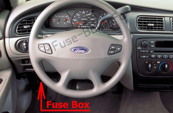
Engine compartment
The power distribution box is located in the engine compartment.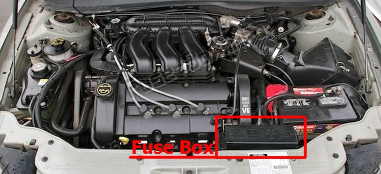
Fuse box diagrams
2000
Passenger compartment
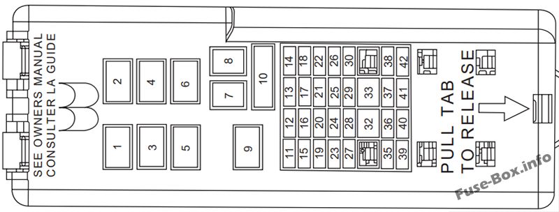
Assignment of the fuses in the Passenger compartment (2000)
| № | Amp Rating | Description |
|---|---|---|
| 1 | — | Accessory Delay Relay |
| 2 | — | Driver One Touch Down Relay |
| 3 | — | Blower Motor Relay |
| 4 | — | Flasher Relay |
| 5 | — | Not Used |
| 6 | — | Not Used |
| 7 | 40A | Rear Defrost Grid Feed |
| 8 | 40A | Blower Motor |
| 9 | — | Rear Defrost Relay |
| 10 | 30A | Power Seats, Delayed Accessory, Adjustable Pedals |
| 11 | 15A | Integrated Control Panel (ICP), Rear Washer Wiper Control, Front Washer, Cell Phone, Passenger Switch Illumination, GEM, Rear Wiper Motor |
| 12 | 10A | Heated Mirrors, Rear Defrost Switch |
| 13 | 20 A | Cigar Lighter, Auxiliary Power Point |
| 14 | — | Not Used |
| 15 | 30A | Front Wiper Motor |
| 16 | 15A | Flasher and GEM Power, Integrated Control Panel (ICP) Power, RCC Memory, Cluster |
| 17 | 15A | Stop Lamp, Speed Control Deactivating Switch |
| 18 | — | Not Used |
| 19 | — | Not Used |
| 20 | — | Not Used |
| 21 | — | Not Used |
| 22 | 20 A | Deck Lid Release Solenoid, Lock/Unlock Relays |
| 23 | 10A | Air Bag Module, PATS Transceiver |
| 24 | 15A | Transit Relay |
| 25 | 2A | PCM Relay |
| 26 | 10A | Mirrors, Power Antenna, Pulse Stretcher Module, Deck Lid Lamp, Batteiy Saver |
| 27 | 10A | Gauges and Warning Lamps, Integrated Control Panel (ICP), FFV Sender, GEM |
| 28 | 10A | Blower Motor Relay Coil, EATC Logic |
| 29 | 15A | Autolamps, Headlamp Switch |
| 30 | 15A | Horns and Horn Switch, OBD II Connector |
| 31 | — | Not Used |
| 32 | 10A | ABS, DRL Relay Coil, Speed Control Actuator, Traction Control Switch, AC Heater Selector Switch, Blend Door Actuator, Brake Shift Interlock |
| 33 | — | Not Used |
| 34 | — | Not Used |
| 35 | — | Not Used |
| 36 | 15A | Turn Signals, Back-up Lamps |
| 37 | 15A | Transmission Position Switch |
| 38 | 5A | GEM Park Neutral Switch |
| 39 | — | Not Used |
| 40 | — | Not Used |
| 41 | — | Not Used |
| 42 | — | Not Used |
Engine compartment
Assignment of the fuses in the Power distribution box (2000)
| № | Amp Rating | Description |
|---|---|---|
| 1 | 60A** | Fuse Junction Panel |
| 2 | 30A** | PCM Relay |
| 3 | 60A** | Fuse Junction Panel |
| 4 | — | Not Used |
| 5 | — | Not Used |
| 6 | — | Not Used |
| 7 | 40A** | Starter Relay, Ignition Switch |
| 8 | 20A** | Transit Relay (Export only) |
| 9 | 40A** | Cooling Fan Relays |
| 10 | — | Not Used |
| 11 | 20A** | Thermactor Relay (FFV only) |
| 12 | — | Not Used |
| 13 | 40A** | Anti-Lock Brake Module Pump Feed |
| 14 | — | Not Used |
| 15 | 20A* | Anti-Lock Brake Module Valve Solenoid |
| 16 | 20A* | Fuel Pump Relay |
| 17 | 20A* | Rear Control Unit, CD Changer, Cell Phone |
| 18 | — | Not Used |
| 19 | 15 A* | Right Headlamp |
| 20 | — | Not Used |
| 21 | 15 A* | Left Headlamp |
| 22 | 10 A* | A/C Clutch Relay, PCM Keep Alive Power |
| 23 | — | Starter Motor Relay |
| 24 | — | Low Speed Fan Relay |
| 25 | — | Wiper Speed Relay |
| 26 | 30A* | Generator |
| 27 | 5A* | Rear Control Unit, Antenna |
| 28 | 15 A* | HEGO Sensor Transmission Shift Solenoid, Canister Vent, A/C Clutch Relay, Thermactor Bypass Solenoid |
| 29 | — | Wiper Park Relay |
| 30 | — | Fuel Pump Relay |
| 31 | — | PCM Power Relay |
| 32 | — | High Speed Fan Relay |
| 33 | — | A/C Clutch Relay |
| * Mini Fuses ** Maxi Fuses |
2001
Passenger compartment
Assignment of the fuses in the Passenger compartment (2001)
| № | Amp Rating | Description |
|---|---|---|
| 1 | — | Accessory Delay Relay |
| 2 | — | Driver One Touch Down Relay |
| 3 | — | Blower Motor Relay |
| 4 | — | Flasher Relay |
| 5 | — | Not Used |
| 6 | — | Not Used |
| 7 | 40 A | Rear Defrost Grid Feed |
| 8 | 40 A | Blower Motor |
| 9 | — | Rear Defrost Relay |
| 10 | 30A | Power Seats, Delayed Accessory, Adjustable Pedals |
| 11 | 15A | Integrated Control Panel (ICP), Rear Washer Wiper Control, Front Washer, Cell Phone, Passenger Switch Illumination, GEM, Rear Wiper Motor |
| 12 | 10A | Heated Mirrors, Rear Defrost Switch |
| 13 | 20A | Power Point |
| 14 | — | Not Used |
| 15 | 30A | Front Wiper Motor |
| 16 | 15A | Flasher and GEM Power, Integrated Control Panel (ICP) Power, RCC Memory, Cluster |
| 17 | 15A | Stop Lamp, Speed Control Deactivating Switch |
| 18 | — | Not Used |
| 19 | — | Not Used |
| 20 | — | Not Used |
| 21 | — | Not Used |
| 22 | 20A | Deck Lid Release Solenoid, Lock/Unlock Relays |
| 23 | 10A | Air Bag Module, PATS Transceiver |
| 24 | 15A | Transit Relay |
| 25 | 2A | PCM Relay |
| 26 | 10A | Mirrors, Power Antenna, Pulse Stretcher Module, Deck Lid Lamp, Battery Saver |
| 27 | 10A | Gauges and Warning Lamps, Integrated Control Panel (ICP), FFV Sender, GEM |
| 28 | 10A | Blower Motor Relay Coil, EATC Logic |
| 29 | 15A | Autolamps, Headlamp Switch |
| 30 | 15A | Horns and Horn Switch, OBD II Connector |
| 31 | — | Not Used |
| 32 | 10A | ABS, DRL Relay Coil, Speed Control Actuator, Traction Control Switch, AC Heater Selector Switch, Blend Door Actuator, Brake Shift Interlock |
| 33 | — | Not Used |
| 34 | — | Not Used |
| 35 | — | Not Used |
| 36 | 15A | Turn Signals, Back-up Lamps |
| 37 | 15A | Transmission Position Switch |
| 38 | 5A | GEM Park Neutral Switch |
| 39 | — | Not Used |
| 40 | — | Not Used |
| 41 | — | Not Used |
| 42 | — | Not Used |
Engine compartment
Assignment of the fuses in the Power distribution box (2001)
| № | Amp Rating | Description |
|---|---|---|
| 1 | 60A** | Fuse Junction Panel |
| 2 | 30A** | PCM Relay |
| 3 | 60A** | Fuse Junction Panel |
| 4 | — | Not Used |
| 5 | — | Not Used |
| 6 | — | Not Used |
| 7 | 40A** | Starter Relay, Ignition Switch |
| 8 | 20A** | Transit Relay (Export only) |
| 9 | 40A** | Cooling Fan Relays |
| 10 | — | Not Used |
| 11 | 20A** | Thermactor Relay (FFV only) |
| 12 | — | Not Used |
| 13 | 40A** | Anti-Lock Brake Module Pump Feed |
| 14 | — | Not Used |
| 15 | 20 A* | Anti-Lock Brake Module Valve Solenoid |
| 16 | 20 A* | Fuel Pump Relay |
| 17 | 20 A* | Rear Control Unit, CD Changer, Cell Phone |
| 18 | 20 A* | Cigar Lighter |
| 19 | 15 A* | Right Headlamp |
| 20 | — | Not Used |
| 21 | 15 A* | Left Headlamp |
| 22 | 10 A* | A/C Clutch Relay, PCM Keep Alive Power |
| 23 | — | Starter Motor Relay |
| 24 | — | Low Speed Fan Relay |
| 25 | — | Wiper Speed Relay |
| 26 | 10 A* | Generator |
| 27 | 5A* | Rear Control Unit, Antenna |
| 28 | 15 A* | HEGO Sensor Transmission Shift Solenoid, Canister Vent, A/C Clutch Relay, Thermactor Bypass Solenoid |
| 29 | — | Wiper Park Relay |
| 30 | — | Fuel Pump Relay |
| 31 | — | PCM Power Relay |
| 32 | — | High Speed Fan Relay |
| 33 | — | A/C Clutch Relay |
| * Mini Fuses ** Maxi Fuses |
2002
Passenger compartment
Assignment of the fuses in the Passenger compartment (2002)
| № | Amp Rating | Description |
|---|---|---|
| 1 | — | Accessory delay relay |
| 2 | — | Driver one touch down relay |
| 3 | — | Blower motor relay |
| 4 | — | Flasher relay |
| 5 | — | Not used |
| 6 | — | Not used |
| 7 | 40A | Rear defrost grid feed |
| 8 | 40A | Blower motor |
| 9 | — | Rear defrost relay |
| 10 | 30A | Circuit breaker: Power seats, Delayed accessory, Adjustable pedals |
| 11 | 15A | Integrated control panel (ICP), Rear washer wiper control, Front washer, Cell phone, Passenger switch illumination, GEM, Rear wiper motor |
| 12 | 10A | Heated mirrors, Rear defrost switch |
| 13 | 20A | Power point |
| 14 | — | Not used |
| 15 | 30A | Front wiper motor |
| 16 | 15A | Flasher and GEM power, Integrated control panel (ICP) power, RCC memory, Cluster |
| 17 | 15A | Stop lamp, Speed control deactivating switch |
| 18 | — | Not used |
| 19 | — | Not used |
| 20 | — | Not used |
| 21 | — | Not used |
| 22 | 20A | Deck lid release solenoid, Lock/unlock relays |
| 23 | 10A | Air bag module, PATS transceiver |
| 24 | 15A | Transit relay |
| 25 | 2A | PCM relay, Fuel pump relay |
| 26 | 10A | Mirrors, Power antenna, Pulse stretcher module, Deck lid lamp, Batteiy saver |
| 27 | 10A | Gauges and warning lamps, Integrated control panel (ICP), FFV sender, GEM |
| 28 | 10A | Blower motor relay coil, EATC logic, Puddle lamps |
| 29 | 15A | Autolamps, Park lamps, PWM, Headlamp switch |
| 30 | 15A | Horns and horn switch, OBD II connector |
| 31 | — | Not used |
| 32 | 10A | ABS, DRL relay coil, Speed control actuator, Traction control switch, AC heater selector switch, Blend door actuator, Brake shift interlock, Rear defroster relay coil |
| 33 | — | Not used |
| 34 | — | Not used |
| 35 | — | Not used |
| 36 | 15A | Turn signals, Back-up lamps |
| 37 | 15A | Transmission position switch |
| 38 | 5A | GEM park neutral switch |
| 39 | — | Not used |
| 40 | — | Not used |
| 41 | — | Not used |
| 42 | — | Not used |
Engine compartment
Assignment of the fuses in the Power distribution box (2002)
| № | Amp Rating | Description |
|---|---|---|
| 1 | 60A** | Fuse junction panel |
| 2 | 30A** | PCM relay |
| 3 | 60A** | Fuse junction panel |
| 4 | — | Not used |
| 5 | — | Not used |
| 6 | — | Not used |
| 7 | 40A** | Starter relay, Ignition switch |
| 8 | 20A** | Transit relay (export only) |
| 9 | 40A** | Cooling fan relays |
| 10 | — | Not used |
| 11 | — | Not used |
| 12 | — | Not used |
| 13 | 40A** | Anti-lock brake module pump feed |
| 14 | — | Not used |
| 15 | 20A* | Anti-lock brake module valve solenoid |
| 16 | 20A* | Fuel pump relay |
| 17 | 20A* | Cell port |
| 18 | 20A* | Cigar lighter |
| 19 | 15 A* | Right headlamp |
| 20 | — | Not used |
| 21 | 15 A* | Left headlamp |
| 22 | 10 A* | A/C clutch relay, PCM keep alive power |
| 23 | — | Starter motor relay |
| 24 | — | Fan relay |
| 25 | — | Wiper speed relay |
| 26 | 10 A* | Alternator |
| 27 | 5A* | Rear control unit, Antenna |
| 28 | 15 A* | HEGO sensor transmission shift solenoid, Canister vent, A/C clutch relay |
| 29 | — | Wiper park relay |
| 30 | — | Fuel pump relay |
| 31 | — | PCM power relay |
| 32 | — | Fan relay |
| 33 | — | A/C clutch relay |
| * Mini Fuses ** Maxi Fuses |
2003
Passenger compartment
Assignment of the fuses in the Passenger compartment (2003)
| № | Amp Rating | Description |
|---|---|---|
| 1 | — | Accessoiy delay relay |
| 2 | — | Driver one touch down relay |
| 3 | — | Blower motor relay |
| 4 | — | Flasher relay |
| 5 | — | Not used |
| 6 | — | Not used |
| 7 | 40A | Rear defrost grid feed (wagon only)/Rear defrost relay coil feed (sedan only) |
| 8 | 40A | Blower motor |
| 9 | — | Rear defrost relay |
| 10 | 30A | Circuit breaker: Power seats, Delayed accessory, Adjustable pedals |
| 11 | 15A | Integrated control panel (ICP), Rear washer wiper control, Front washer, Cell phone, Passenger switch illumination, GEM, Rear wiper motor |
| 12 | 10A | Heated mirrors, Rear defrost switch |
| 13 | 20A | Cigar lighter (if equipped) |
| 14 | — | Not used |
| 15 | 30A | Front wiper motor |
| 16 | 15A | Flasher and GEM power, ICP power, RCC memory, Cluster |
| 17 | 15A | Stop lamp, Speed control deactivating switch |
| 18 | — | Not used |
| 19 | — | Not used |
| 20 | — | Not used |
| 21 | — | Not used |
| 22 | 20A | Deck lid release solenoid, Lock/unlock relays |
| 23 | 10A | Air bag module, PATS transceiver |
| 24 | — | Not used |
| 25 | 2A | PCM relay, Fuel pump relay |
| 26 | 10A | Mirrors, Power antenna, Pulse stretcher module, Deck lid lamp, Battery saver |
| 27 | 10A | Gauges and warning lamps, ICP, FFV sender, GEM |
| 28 | 10A | Blower motor relay coil, EATC logic, Puddle lamps |
| 29 | 15A | Autolamps, Park lamps, PWM, Headlamp switch |
| 30 | 15A | Horns and horn switch, OBD II connector |
| 31 | — | Not used |
| 32 | 10A | ABS, DRL relay coil, Speed control actuator, Traction control switch, AC heater selector switch, Blend door actuator, Brake shift interlock, Rear defroster relay coil |
| 33 | — | Not used |
| 34 | — | Not used |
| 35 | — | Not used |
| 36 | 15A | Turn signals, Back-up lamps |
| 37 | 15A | Transmission position switch |
| 38 | 5A | GEM park neutral switch |
| 39 | — | Not used |
| 40 | — | Not used |
| 41 | — | Not used |
| 42 | — | Not used |
Engine compartment
Assignment of the fuses in the Power distribution box (2003)
| № | Amp Rating | Description |
|---|---|---|
| 1 | 60A** | Fuse junction panel |
| 2 | 30A** | Powertrain Control Module (PCM) relay |
| 3 | 60A** | Fuse junction panel |
| 4 | — | Not used |
| 5 | — | Not used |
| 6 | — | Not used |
| 7 | 40A** | Starter relay, Ignition switch |
| 8 | — | Not used |
| 9 | 40A** | Cooling fan relays |
| 10 | — | Not used |
| 11 | 50A** | Rear defrost (sedan only) |
| 12 | — | Not used |
| 13 | 40A** | Anti-lock Brake System (ABS) module pump feed |
| 14 | — | Not used |
| 15 | 20 A* | ABS module valve solenoid |
| 16 | 20 A* | Fuel pump relay |
| 17 | 20 A* | Cell port |
| 18 | 20 A* | Power point |
| 19 | 15 A* | Right headlamp |
| 20 | — | Not used |
| 21 | 15 A* | Left headlamp |
| 22 | 10 A* | A/C clutch relay, PCM keep alive power |
| 23 | — | Starter motor relay |
| 24 | — | Fan relay |
| 25 | — | Wiper speed relay |
| 26 | 10 A* | Alternator |
| 27 | 5A* | Rear control unit, Antenna |
| 28 | 15 A* | HEGO sensor t ransmission shift solenoid, Canister vent, A/C clutch relay |
| 29 | — | Wiper park relay |
| 30 | — | Fuel pump relay |
| 31 | — | PCM power relay |
| 32 | — | Fan relay |
| 33 | — | A/C clutch relay |
| * Mini Fuses ** Maxi Fuses |
2004
Passenger compartment
Assignment of the fuses in the Passenger compartment (2004)
| № | Amp Rating | Description |
|---|---|---|
| 14 | — | Not used |
| 15 | 10A | Left headlamp |
| 16 | 10A | Not used (spare) |
| 17 | 15A | Stop lamp, Speed control deactivation switch |
| 18 | 15A | Parklamps, PWM (backlighting), Autolamps |
| 19 | 10A | Heated mirrors, Rear defrost swatch indicator |
| 20 | 10A | Restraints (air bag module/OCS module) |
| 21 | 15A | Transmission range sensor (transmission position swatch) |
| 22 | 15A | Front washer pump, Electrochromatic mirror, Compass, Cluster (RUN/ACC), Integrated Control Panel (ICP) logic, Rear wiper (wagon only), Rear washer (wagon only) |
| 23 | 30A | Front wiper motor |
| 24 | — | Not used |
| 25 | 20A | Power point |
| 26 | 20A | Power locks, Liftgate (wagon)/Trunk (sedan) release |
| 27 | 10A | Anti-lock Brake System (ABS), Speed control, Traction control, Brake-shift interlock, A/C function switch (manual A/C only), Temperature blend door (manual A/C only), Defrost coil |
| 28 | 15A | Turn signals, Back-up lamps |
| 29 | 20A | Cigar lighter |
| 1 | — | Accessory delay relay |
| 2 | — | Driver one touch down relay |
| 3 | — | Blower motor relay |
| 4 | — | Flasher relay |
| 5 | — | Not used |
| 6 | — | Not used |
| 7 | 20A | Rear defrost grid feed (wagon only)/Rear defrost relay coil feed (sedan only) |
| 8 | 40 A | Blower motor |
| 9 | — | Rear defrost relay |
| 10 | 30A Circuit Breaker | Power seats, Delayed accessoiy, Adjustable pedals |
| 11 | 10A | Right headlamp |
| 12 | 15A | Highbeam headlamps |
| 13 | — | Not used |
| 30 | 10A | Courtesy lighting, Battery saver, Power mirrors, Decklid lamp, Power antenna (wagon only), Pulse stretching module (wagon only) |
| 31 | 10A | Blower motor relay coil, Puddle lamp relay coil, Electronic Automatic Temperature Control (EATC) logic |
| 32 | 10A | Cluster, Flex fuel module, ICP logic, Passive anti-theft module (GEM power) |
| 33 | 15A | Hazard flasher, Cluster power, ICP power, EATC |
| 34 | 5A | GEM logic |
| 35 | 10A | Backlighting |
| 36 | 2A | Powertrain Control Module (PCM) relay, Fuel pump relay, A/C clutch |
| 37 | 25A | Autolamp, Daytime Running Lamps (DRL), Flash-to-pass, Headlamp swatch |
| 38 | 15A | Horn, Diagnostic connector (OBD II) |
| 39 | — | Not used |
| 40 | — | Not used |
| 41 | — | Not used |
| 42 | — | Not used |
Engine compartment
Assignment of the fuses in the Power distribution box (2004)
| № | Amp Rating | Description |
|---|---|---|
| 1 | 60A** | Fuse junction panel |
| 2 | 30A** | Powertrain Control Module (PCM) |
| 3 | 60A** | Fuse junction panel |
| 4 | 10A CB | Low speed cooling fan (Not used in GCC) |
| 5 | 40A** | Cooling fan |
| 6 | — | Not used |
| 7 | 40A** | Starter relay, Ignition switch |
| 8 | — | Not used |
| 9 | 20A** (50A** in GCC) | Cooling fan (passenger side) |
| 10 | 20A** | Cooling fan (driver side) (not used in GCC) |
| 11 | 50A** | Rear defrost (sedan only) |
| 12 | — | Not used |
| 13 | 40A** | Anti-lock Brake System (ABS) module pump feed |
| 14 | — | Not used |
| 15 | 20 A* | ABS module valve solenoid |
| 16 | 20 A* | Fuel pump relay |
| 17 | 20 A* | CD |
| 18 | — | Not used |
| 19 | — | Not used |
| 20 | — | Not used |
| 21 | — | Not used |
| 22 | 10 A* | A/C clutch relay, PCM keep alive power |
| 23 | — | Starter motor relay |
| 24 | — | Fan relay |
| 25 | — | Wiper speed relay |
| 26 | 10 A* | Alternator |
| 27 | 5A* | Rear control unit, Antenna |
| 28 | 15 A* | HEGO sensor, Transmission shift solenoid, Canister vent, A/C clutch relay |
| 29 | — | Wiper park relay |
| 30 | — | Fuel pump relay |
| 31 | — | PCM power relay |
| 32 | — | Fan relay |
| 33 | — | A/C clutch relay |
| * – Mini Fuses ** – Maxi Fuses CB – Circuit breaker |
2005
Passenger compartment
Assignment of the fuses in the Passenger compartment (2005)
| № | Amp Rating | Description |
|---|---|---|
| 1 | — | Accessoiy delay relay |
| 2 | — | Driver one touch down relay |
| 3 | — | Blower motor relay |
| 4 | — | Flasher relay |
| 5 | — | Not used |
| 6 | — | Not used |
| 7 | 20A | Rear defrost grid feed (wagon only)/Rear defrost relay coil feed (sedan only) |
| 8 | 40A | Blower motor |
| 9 | — | Rear defrost relay |
| 10 | 30A Circuit Breaker | Power seats, Delayed accessory, Adjustable pedals |
| 11 | 10A | Right headlamp |
| 12 | 15A | Highbeam headlamps |
| 13 | — | Not used |
| 14 | — | Not used |
| 15 | 10A | Left headlamp |
| 16 | 10A | Not used (spare) |
| 17 | 15A | Stop lamp, Speed control deactivation switch |
| 18 | 15A | Parklamps, PWM (backlighting), Autolamps |
| 19 | 10A | Heated mirrors, Rear defrost switch indicator |
| 20 | 10A | Restraints (air bag module/OCS module) |
| 21 | 15A | Transmission range sensor (transmission position switch) |
| 22 | 15A | Front washer pump, Electrochromatic mirror, Compass, Cluster (RUN/ACC), Integrated Control Panel (ICP) logic, Rear wiper (wagon only), Rear washer (wagon only) |
| 23 | 30A | Front wiper motor |
| 24 | — | Not used |
| 25 | 20A | Power point |
| 26 | 20A | Power locks, Liftgate (wagon)/Trunk (sedan) release |
| 27 | 10A | Anti-lock Brake System (ABS), Speed control, Traction control, Brake-shift interlock, A/C function switch (manual A/C only), Temperature blend door (manual A/C only), Defrost coil |
| 28 | 15A | Turn signals, Back-up lamps |
| 29 | 20A | Cigar lighter |
| 30 | 10A | Courtesy lighting, Battery saver, Power mirrors, Decklid lamp, Power antenna (wagon only), Pulse stretching module (wagon only) |
| 31 | 10A | Blower motor relay coil, Puddle lamp relay coil, Electronic Automatic Temperature Control (EATC) logic |
| 32 | 10A | Cluster, Flex fuel module, ICP logic, Passive anti-theft module (GEM power) |
| 33 | 15A | Hazard flasher, Cluster power, ICP power, EATC |
| 34 | 5A | GEM logic |
| 35 | 10A | Backlighting |
| 36 | 2A | Powertrain Control Module (PCM) relay, Fuel pump relay, A/C clutch |
| 37 | 25A | Autolamp, Daytime Running Lamps (DRL), Flash-to-pass, Headlamp switch |
| 38 | 15A | Horn, Diagnostic connector (OBD id |
| 39 | — | Not used |
| 40 | — | Not used |
| 41 | — | Not used |
| 42 | — | Not used |
Engine compartment
Assignment of the fuses in the Power distribution box (2005)
| № | Amp Rating | Description |
|---|---|---|
| 1 | 60 A** | Fuse junction panel |
| 2 | 30A** | Powertrain Control Module (PCM) |
| 3 | 60 A** | Fuse junction panel |
| 4 | 10A CB | Low speed cooling fan |
| 5 | 40A** | Cooling fan |
| 6 | — | Not used |
| 7 | 40A** | Starter relay, Ignition switch |
| 8 | — | Not used |
| 9 | 20A** | Cooling fan (passenger side) |
| 10 | 20A** | Cooling fan (driver side) |
| 11 | 50A** | Rear defrost (sedan only) |
| 12 | — | Not used |
| 13 | 40A** | Anti-lock Brake System (ABS) module pump feed |
| 14 | — | Not used |
| 15 | 20A* | ABS module valve solenoid |
| 16 | 20A* | Fuel pump relay |
| 17 | 20A* | CD |
| 18 | 10A* (Vulcan engine only) | A/C clutch relay, PCM keep alive power |
| 18 | – (Duratec engine only) | Not used power |
| 19 | — | Not used |
| 20 | — | Not used |
| 21 | — | Not used |
| 22 | 5A* (Vulcan engine only) | Heated PCV valve |
| 22 | 10A* (Duratec engine only) | A/C clutch relay, PCM keep alive power |
| 23 | — | Starter motor relay |
| 24 | — | Fan relay |
| 25 | — | Wiper speed relay |
| 26 | 10 A* | Alternator |
| 27 | 5A* | Rear control unit, Antenna |
| 28 | 15 A* | HEGO sensor, Transmission shift solenoid, Canister vent, A/C clutch relay |
| 29 | — | Wiper park relay |
| 30 | — | Fuel pump relay |
| 31 | — | PCM power relay |
| 32 | — | Fan relay |
| 33 | — | A/C clutch relay |
| * – Mini Fuses ** – Maxi Fuses CB – Circuit breaker |
2006
Passenger compartment
Assignment of the fuses in the Passenger compartment (2006)
| № | Amp Rating | Description |
|---|---|---|
| 1 | — | Accessory delay relay |
| 2 | — | Driver one touch down relay |
| 3 | — | Blower motor relay |
| 4 | — | Flasher relay |
| 5 | — | Not used |
| 6 | — | Not used |
| 7 | 20 A | Rear defrost relay coil feed |
| 8 | 40 A | Blower motor |
| 9 | — | Rear defrost relay |
| 10 | 30A Circuit Breaker | Power seats, Delayed accessory |
| 11 | 10A | Right headlamp |
| 12 | 15A | Highbeam headlamps |
| 13 | — | Not used |
| 14 | — | Not used |
| 15 | 10A | Left headlamp |
| 16 | 10A | Not used (spare) |
| 17 | 15A | Stop lamp, Speed control deactivation switch |
| 18 | 15A | Parklamps, PWM (backlighting), Autolamps |
| 19 | 10A | Heated mirrors, Rear defrost switch indicator |
| 20 | 10A | Restraints (air bag module/OCS module) |
| 21 | 15A | Transmission range sensor (transmission position switch) |
| 22 | 15A | Front washer pump, Cluster (RUN/ACC), Integrated Control Panel (ICP) logic, Electrochromatic mirror |
| 23 | 30 A | Front wiper motor |
| 24 | — | Not used |
| 25 | 20 A | Power point |
| 26 | 20 A | Power locks, Trunk release |
| 27 | 10A | Anti-lock Brake System (ABS), Speed control, Traction control, Brake-shift interlock, A/C function switch (manual A/C only), Temperature blend door (manual A/C only), Defrost coil |
| 28 | 15A | Turn signals, Back-up lamps |
| 29 | 20 A | Cigar lighter |
| 30 | 10A | Courtesy lighting, Battery saver, Power mirrors, Decklid lamp, Glove box lamp |
| 31 | 10A | Blower motor relay coil, Electronic Automatic Temperature Control (EATC) logic |
| 32 | 10A | Cluster, Flex fuel module, ICP logic, Passive anti-theft module (GEM power), Compass |
| 33 | 15A | Hazard flasher, Cluster power, ICP power, EATC |
| 34 | 5A | GEM logic |
| 35 | 10A | Backlighting, Ashtray light |
| 36 | 2A | Powertrain Control Module (PCM) relay, Fuel pump relay, A/C clutch |
| 37 | 25A | Autolamp, Daytime Running Lamps (DRL), Flash-to-pass, Headlamp switch |
| 38 | 15A | Horn, Diagnostic connector (OBD II) |
| 39 | — | Not used |
| 40 | — | Not used |
| 41 | — | Not used |
| 42 | — | Not used |
Engine compartment
Assignment of the fuses in the Power distribution box (2006)
| № | Amp Rating | Description |
|---|---|---|
| 1 | 60A** | Fuse junction panel |
| 2 | 30A** | Powertrain Control Module (PCM) |
| 3 | 60A** | Fuse junction panel |
| 4 | 10A CB | Low speed cooling fan |
| 5 | 40A** | Cooling fan (main) |
| 6 | — | Not used |
| 7 | 40A** | Starter relay, Ignition switch |
| 8 | — | Not used |
| 9 | 20A** | Cooling fan (passenger side) |
| 10 | 20A** | Cooling fan (driver side) |
| 11 | 50A** | Rear defrost |
| 12 | — | Not used |
| 13 | 40A** | Anti-lock Brake System (ABS) module pump feed |
| 14 | — | Not used |
| 15 | 20 A* | ABS module valve solenoid |
| 16 | 20 A* | Fuel pump relay |
| 17 | 20 A* | CD |
| 18 | 10 A* | A/C clutch relay, PCM keep alive power |
| 19 | — | Not used |
| 20 | — | Not used |
| 21 | — | Not used |
| 22 | 5A* | Heated PCV valve |
| 23 | — | Starter motor relay |
| 24 | — | Fan relay |
| 25 | — | Wiper speed relay |
| 26 | 10 A* | Alternator |
| 27 | 5A* | Rear control unit |
| 28 | 15 A* | HEGO sensor, Transmission shift solenoid, A/C clutch relay, Canister vent |
| 29 | — | Wiper park relay |
| 30 | — | Fuel pump relay |
| 31 | — | PCM power relay |
| 32 | — | Fan relay |
| 33 | — | A/C clutch relay |
| * – Mini Fuses ** – Maxi Fuses CB – Circuit breaker |
2007
Passenger compartment
Assignment of the fuses in the Passenger compartment (2007)
| № | Amp Rating | Description |
|---|---|---|
| 1 | — | Accessory delay relay |
| 2 | — | Driver one touch down relay |
| 3 | — | Blower motor relay |
| 4 | — | Flasher relay |
| 5 | — | Not used |
| 6 | — | Not used |
| 7 | 20A | Rear defrost relay coil feed |
| 8 | 40A | Blower motor |
| 9 | — | Rear defrost relay |
| 10 | 30A Circuit Breaker | Power seats, Delayed accessory |
| 11 | 10A | Left headlamp |
| 12 | 15A | Highbeam headlamps |
| 13 | — | Not used |
| 14 | — | Not used |
| 15 | 10A | Right headlamp |
| 16 | 10A | Not used (spare) |
| 17 | 15A | Stop lamp, Speed control deactivation switch |
| 18 | 15A | Parklamps, PWM (backlighting), Autolamps |
| 19 | 10A | Heated mirrors, Rear defrost switch indicator |
| 20 | 10A | Restraints (air bag module/OCS module) |
| 21 | 15A | Transmission range sensor (transmission position switch) |
| 22 | 15A | Front washer pump, Cluster (RUN/ACC), Integrated Control Panel (1CP) logic, Electrochromatic mirror |
| 23 | 30A | Front wiper motor |
| 24 | — | Not used |
| 25 | 20 A | Power point |
| 26 | 20 A | Power locks, Trunk release |
| 27 | 10A | Anti-lock Brake System (ABS), Speed control, Traction control, Brake-shift interlock, A/C function switch (manual A/C only), Temperature blend door (manual A/C only), Defrost coil |
| 28 | 15A | lurn signals, Back-up lamps |
| 29 | 20A | Cigar lighter |
| 30 | 10A | Courtesy lighting, Battery saver, Power mirrors, Decklid lamp, Glove box lamp |
| 31 | 10A | Blower motor relay coil, Electronic Automatic Temperature Control (EATC) logic |
| 32 | 10A | Cluster, Flex fuel module, ICP logic, Passive anti-theft module (GEM power), Compass |
| 33 | 15A | Hazard flasher, Cluster power, ICP power, EATC |
| 34 | 5A | GEM logic |
| 35 | 10A | Backlighting, Ashtray light |
| 36 | 2A | Powertrain Control Module (PCM) relay, Fuel pump relay, A/C clutch |
| 37 | 25A | Autolamp, Daytime Running Lamps (DRL), Flash-to-pass, Headlamp switch |
| 38 | 15A | Horn, Diagnostic connector (OBD II) |
| 39 | — | Not used |
| 40 | — | Not used |
| 41 | — | Not used |
| 42 | — | Not used |
Engine compartment
Assignment of the fuses in the Power distribution box (2007)
| № | Amp Rating | Description |
|---|---|---|
| 1 | 60A** | Fuse junction panel |
| 2 | 30A** | Powertrain Control Module (PCM) |
| 3 | 60A** | Fuse junction panel |
| 4 | 10A CB | Low speed cooling fan |
| 5 | 40A** | Cooling fan (main) |
| 6 | — | Not used |
| 7 | 40A** | Starter relay, Ignition switch |
| 8 | — | Not used |
| 9 | 20A** | Cooling fan (passenger side) |
| 10 | 20A** | Cooling fan (driver side) |
| 11 | 50A** | Rear defrost |
| 12 | — | Not used |
| 13 | 40A** | Anti-lock Brake System (ABS) module pump feed |
| 14 | — | Not used |
| 15 | 20A* | ABS module valve solenoid |
| 16 | 20A* | Fuel pump relay |
| 17 | 20A* | CD |
| 18 | 10A* | A/C clutch relay, PCM keep alive power |
| 19 | — | Not used |
| 20 | — | Not used |
| 21 | — | Not used |
| 22 | 5A* | Heated PCV valve |
| 23 | — | Starter motor relay |
| 24 | — | Fan relay |
| 25 | — | Wiper speed relay |
| 26 | 10A* | Alternator |
| 27 | 5A* | Rear control unit |
| 28 | 15 A* | HEGO sensor, Transmission shift solenoid, A/C clutch relay, Canister vent |
| 29 | — | Wiper park relay |
| 30 | — | Fuel pump relay |
| 31 | — | PCM power relay |
| 32 | — | Fan relay |
| 33 | — | A/C clutch relay |
| * – Mini Fuses ** – Maxi Fuses CB – Circuit breaker |


