

See other Ford Taurus:


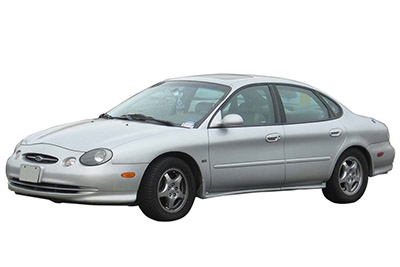
Fuse Layout Ford Taurus 1996-1999
Contents
Cigar lighter (power outlet) fuse in the Ford Taurus is the fuse #21 in the Instrument panel fuse box.
Table of Contents
Passenger compartment fuse box
Passenger compartment fuse box
Fuse box location
The fuse panel is located below and to the left of the steering wheel by the brake pedal.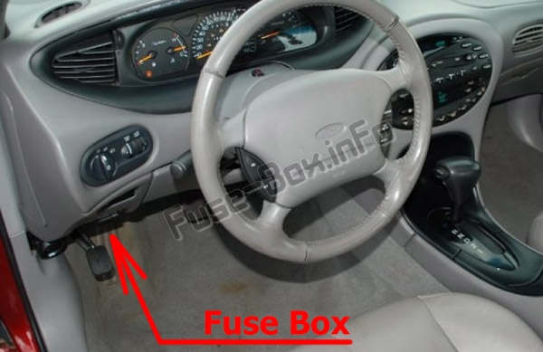
Fuse box diagram
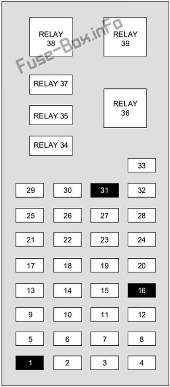
Assignment of the fuses and relays in the Passenger compartment
| № | Amp Rating | Description |
|---|---|---|
| 1 | — | Not Used |
| 2 | 5A | Instrument Illumination |
| 3 | 10A | Left Low Beam Headlamp |
| 4 | 10A | Right Low Beam Headlamp |
| 5 | 5A | Brake Shift Interlock, Rear Defroster |
| 6 | 15A | 1996-1997: MLPS switch, backup lamps, speed control, climate control 1998: MLPS Switch, Backup Lamps, Speed Control 1999: TR Sensor, Reverse Lamps, DRL, A/C Controls |
| 7 | 10A | 1996-1998: MLPS Switch, Starter Relay 1999: TR Sensor, Starter Relay |
| 8 | 5A | Power Antenna, RCU (radio control unit), GEM |
| 9 | 10A | 1996-1997: Anti-lock brakes system, Central Temperature Monitor 1998-1999: ABS |
| 10 | 20A | 1996-1997: EEEC relay, ignition coil, passive anti-theft system, radio 1998-1999: PCM Relay, Ignition Coil, PATS, Radio |
| 11 | 5A | 1996-1997: Air bag indicator, instrument cluster 1998-1999: Instrument Cluster |
| 12 | 5A | Instrument Cluster, Autolamps, Transmission Control Switch, ICP (integrated control panel), GEM |
| 13 | 5A | 1996-1998: Air Bag, Blower Motor, EATC (electronic automatic temperature control) 1999: Electronic Crash Unit (ECU), Blower Motor, EATC (electronic automatic temperature control) |
| 14 | 5A | 1996-1997: Lamp outage indication, Semi-active suspension (SHO only) 1998: Air Suspension 1999: Semi-Active Ride Control Module |
| 15 | 10A | Multi-Function Switch (Turn Signal) |
| 16 | — | Not Used |
| 17 | 30A | Front Wiper/Washer |
| 18 | 5A | Headlamp Switch |
| 19 | 15A | Rear Wiper/Washer |
| 20 | 5A | 1996-1997: Integrated control panel, remote entry, cigar lighter 1998: ICP (Integrated control panel), RAP, Phone 1999: ICP (Integrated control panel), RAP, Phone, GEM |
| 21 | 20A | Cigar Lighter |
| 22 | 5A | Power Mirrors, Power Antenna, Decklid Lamps, Autolamp |
| 23 | 5A | 1996-1997: Wiper system, variable assist steering, remote entry, anti-theft 1998-1999: GEM, RAP, PATS |
| 24 | 5A | 1996-1997: Integrated control panel, speedometer, electronic automatic temperature control module 1998-1999: ICP, RCC, Speedometer |
| 25 | 10A | (DLC) Data Link Connector |
| 26 | 15A | Trunklid |
| 27 | 10A | Battery Saver Relay |
| 28 | 15A | 1996-1997: Brake lamps, stop control 1998-1999: Speed Control, Stop Lamp |
| 29 | 15A | Multi-Function Swatch, Hazard flashers |
| 30 | 15A | High Beams, Daytime Running Lamps, Instrument Cluster |
| 31 | 5A | 1996-1997: Tail lamp feed 1998-1999: Not Used |
| 32 | 10A | ICP (Integrated control panel), Heated Mirrors |
| 33 | 5A | Power Windows, Lock Illumination |
| Relay 34 | — | Battery Saver Relay |
| Relay 35 | — | Driver Door Unlock Relay |
| Relay 36 | — | Rear Defroster Relay |
| Relay 37 | — | Interior Lamp Relay |
| Relay 38 | — | One Touch Window Down Relay |
| Relay 39 | — | Accessory Delay Relay |
Engine compartment fuse box
Engine compartment fuse box
Fuse box location
The power distribution box is located in the engine compartment near the battery.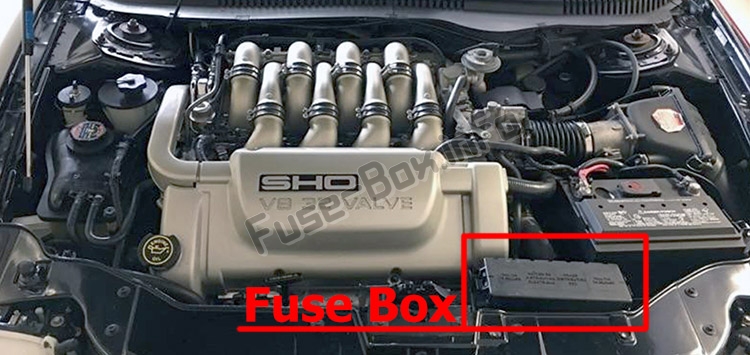
Fuse box diagram
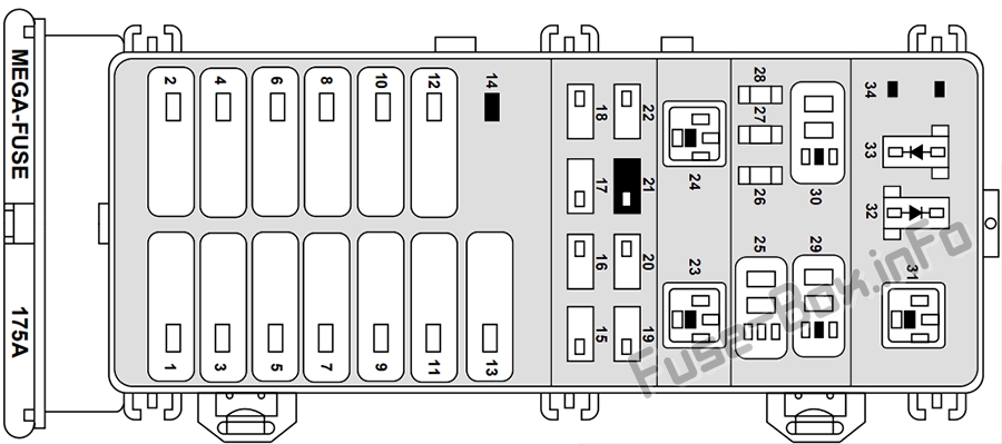
Assignment of the fuses and relays in the Power distribution box
| № | Amp Rating | Description |
|---|---|---|
| 1 | 40A | Fuse Panel |
| 2 | 30 A | 1996-1997: Constant control relay module 1998-1999: PCM Relay |
| 3 | 40A | Ignition Switch, Starter Relay |
| 4 | 30A | 1996-1997: Accessory delay relay 1998: Accessory Delay Relay, Power Windows, Left/Right Power Seats 1999: Accessory Delay Relay, Power Seat |
| 5 | 40A | Ignition Switch |
| 6 | 30 A / — | 1996-1997: Power seats 1998: Left/Right Power Seats / Not Used 1999: Not Used |
| 7 | 40A | Rear Window Defrost Relay |
| 8 | 30A | Thermactor Air ByPass Solenoid, EAM Solid State Relay |
| 9 | 40A | 1996-1997: Constant control relay module 1998-1999: High Speed Cooling Fan Relay, Low Speed Cooling Fan Relay |
| 10 | 20 A | 1996-1997: Constant control relay module 1998-1999: Fuel Pump Relay |
| 11 | 40A | Blower Motor Relay |
| 12 | 20 A | Semi-Active Ride Control Module |
| 13 | 40A | Anti-Lock Brake Module |
| 14 | — | Not Used |
| 15 | 15 A | Daytime Running Lamps (DRL) Module |
| 16 | 10A | 1996-1998: Air Bag Diagnostic Monitor 1999: Electronic Control Unit (ECU) |
| 17 | 20A | Rear Control Unit, CD Changer |
| 18 | 30A | Anti-Lock Brake Module |
| 19 | 15 A | Horn Relay, Powertrain Control Module (PCM) |
| 20 | 15 A | Headlamp Switch, Autolamp Park Relay |
| 21 | — | Not Used |
| 22 | 30A | Autolamps Relay, Multi-Function Switch, Headlamp Switch |
| 23 | — | Blower Motor Relay |
| 24 | — | Starter Relay |
| 25 | — | A/C Clutch Relay |
| 26 | 30A | Generator/Voltage Regulator |
| 27 | 10A | A/C Clutch Relay |
| 28 | 15 A | Heated Oxygen Sensors, Canister Vent |
| 29 | — | Fuel Pump Relay |
| 30 | — | PCM Relay |
| 31 | — | Low Speed Cooling Fan Relay |
| 32 | — | PCM Diode |
| 33 | — | A/C Clutch Diode |
| 34 | — | Not Used |


