


Fuse Layout Ford Explorer 1996-2001
Contents

Cigar lighter (power outlet) fuses in the Ford Explorer are the fuse №17 (Cigar lighter) in the Instrument panel fuse box, and fuse №3 (Power Point) in the Engine compartment fuse box (1996-1997). Since 1998 – fuses №17 (Cigar lighter) and №22 (Auxiliary Power Socket) in the Instrument panel fuse box.
Table of Contents
Fuse box location
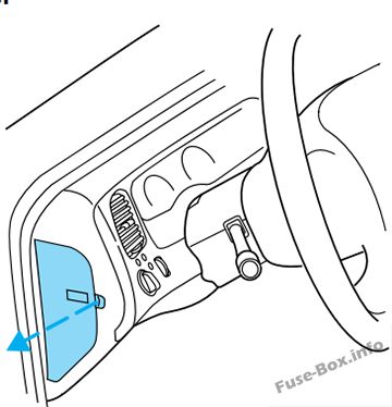
Passenger compartment
The fuse panel is located on the left hand side of the instrument panel facing the driver’s side door.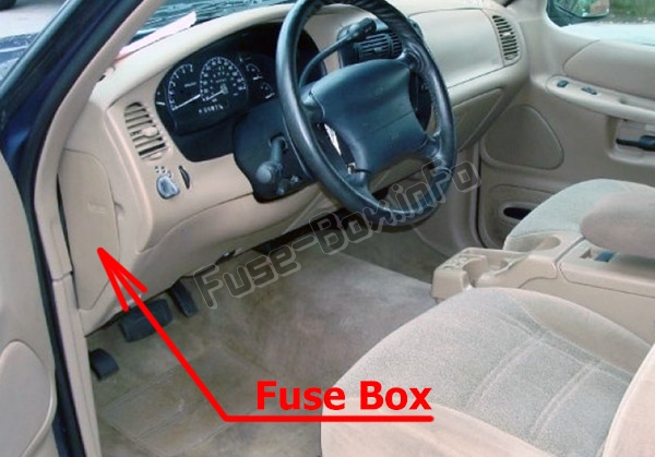
Pull the panel cover outward to access the fuses.
Engine compartment
The power distribution box is located in the engine compartment near the battery.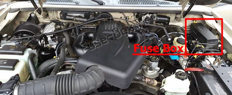
Fuse box diagrams
1996
Passenger compartment
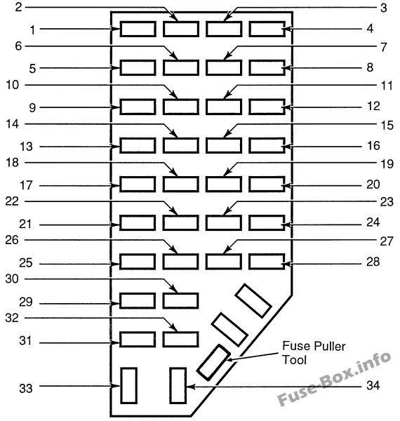
Assignment of the fuses in the Passenger compartment (1996)
| № | Amp Rating | Description |
|---|---|---|
| 1 | 7.5 Amp | Power mirror. Power antenna |
| 2 | 7.5 Amp | High-mount stoplamp |
| 3 | 15 Amp | Parking lamps |
| 4 | 10 Amp | Left headlamp |
| 5 | 10 Amp | OBD system |
| 6 | 7.5 Amp | Air bag system. Blower relay |
| 7 | 7.5 Amp | Ilium, switches |
| 8 | 10 Amp | Right headlamp. Fog lamp system |
| 9 | 10 Amp | EATC memory. Seat memory. Message center. Cellular phone |
| 10 | 7.5 Amp | EATC system. Rear blower. Speed control. GEM system. Brake interlock. Overhead console. Automatic Ride Control |
| 11 | 7.5 Amp | Warning lamps |
| 12 | 10 Amp | Front/rear wash |
| 13 | 15 Amp | PCM system. Stoplamps. 4 wneel drive. Anti-lock brake. Speed control. Trailer tow |
| 14 | 10 Amp | Anti-lock system |
| 15 | 7.5 Amp | Air bag system. Alternator |
| 16 | 30 Amp | Front wiper |
| 17 | 15 Amp | Cigar lighter |
| 18 | 15 Amp | A/C system |
| 19 | 25 Amp | Ignition coil. PCM system |
| 20 | 7.5 Amp | Radio. Power Antenna. GEM system. Anti-theft. Cellular phone |
| 21 | 15 Amp | Hazard lamps |
| 22 | 10 Amp | Turn signals |
| 23 | 10 Amp | Rear wiper system |
| 24 | 10 Amp | Starter relay |
| 25 | 7.5 Amp | Speedometer. GEM system |
| 26 | 10 Amp | 4R44E/4R55E overdrive. DRL system. Backup lamps. 4 wheel drive. Rear defroster |
| 27 | 15 Amp | Under hood lamp. Map lights. Glove dox lamp. Dome lamp. Visor lamps. Accessory delay. Dimmer switch ilium.. 4×4 system |
| 28 | 7.5 Amp | Memory seat. GEM system |
| 29 | 10 Amp | Audio system |
| 30 | – | Not Used |
| 31 | 7.5 Amp | Aux. blower system |
| 32 | 7.5 Amp | Heated mirror. Heated backlite |
| 33 | 15 Amp | High beam lamps |
| 34 | 7.5 Amp | Lux audio system |
Engine compartment
1997
Passenger compartment
Assignment of the fuses in the Passenger compartment (1997)
| № | Amp Rating | Circuits Protected |
|---|---|---|
| 1 | 7.5 amp | Power mirror, power antenna |
| 2 | 7.5 amp | High-mount brakelamp |
| 3 | 15 amp | Parking lamp, instrument cluster gauges |
| 4 | 10 amp | Left headlamp, lamp out warning |
| 5 | 10 amp | OBD system |
| 6 | 7.5 amp | Air bag system, blower relay, EATC |
| 7 | 7.5 amp | Illumination switches |
| 8 | 10 amp | Right headlamp, fog lamp system, DRL, lamp out warning |
| 9 | 10 amp | EATC system, seat memory, message center, cellular phone, autolamps |
| 10 | 7.5 amp | EATC system, rear blower, speed control, GEM system, brake interlock, overhead console, automatic ride control, lamp out warning |
| 11 | 7.5 amp | Warning lamps, autolamp |
| 12 | 10 amp | Front washer, rear washer & wiper |
| 13 | 15 amp | PCM system, stoplamps, AWD, anti-lock brake, speed control, trailer tow |
| 14 | 10 amp | Anti-lock system |
| 15 | 7.5 amp | Air hag system, instrument cluster |
| 16 | 30 amp | Wiper run relay |
| 17 | 25 amp | Cigar lighter |
| 18 | 15 amp | A/C system |
| 19 | 25 amp | Ignition coil, PCM system |
| 20 | 7.5 amp | Radio, power antenna, GEM system, anti-theft, cellular phone |
| 21 | 15 amp | Turn/hazard flasher |
| 22 | 10 amp | Turn signals |
| 23 | 10 amp | Rear wiper system |
| 24 | 10 amp | Starter relay |
| 25 | 7.5 amp | Speedometer, GEM system |
| 26 | 10 amp | 5R55E/4R70W overdrive, DRL system, backup lamps, AWD, rear defroster |
| 27 | 10 amp | Under hood lamp, map lamps, glove box lamp, dome lamp, visor lamps, accessory delay, dimmer switch illumination, 4×4 system |
| 28 | 7.5 amp | Memory seat, GEM system |
| 29 | 10 amp | Audio system |
| 30 | – | Not used |
| 31 | 7.5 amp | Rear blower system |
| 32 | 7.5 amp | Heated mirror, rear defroster |
| 33 | 15 amp | High beam lamps |
| 34 | 7.5 amp | Lux audio system |
Engine compartment

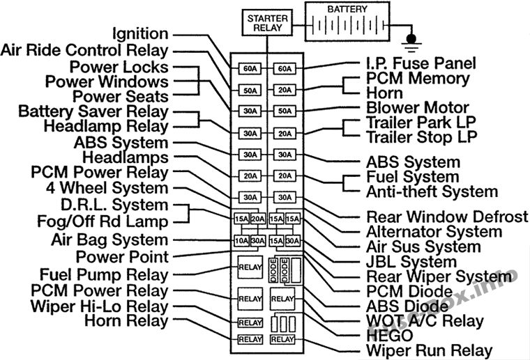
Assignment of the fuses in the Power distribution box (1997)
| № | Amperage | Circuits protected |
|---|---|---|
| Maxi fuses | ||
| 1 | 30 | Rear window defrost |
| 2 | 30 | PCM power relay |
| 3 | 20 | Fuel system, anti-theft system |
| 4 | 20 | Headlamps |
| 5 | 30 | ABS system |
| 6 | 30 | ABS system |
| 7 | 20 | Trailer park LP and trailer stop LP |
| 8 | 30 | Battery saver relay and headlamp relay |
| 9 | 50 | Blower motor |
| 10 | 30 | Power locks, power windows and power seats |
| 11 | 20 | PCM memory and horn |
| 12 | 50 | Air ride control relay |
| 13 | 60 | Instrument panel fuse panel |
| 14 | 60 | Ignition |
| Mini fuses | ||
| 1 | 30 | JBL system |
| 2 | 15 | Rear wiper system |
| 3 | 30 | Power point |
| 4 | 20 | 4WD system |
| 5 | 15 | Air suspension system |
| 6 | 15 | Alternator system |
| 7 | 10 | Air bag system |
| 8 | 15 | DRL/Fog lamps/Off-road lamps |
| 9 | – | Not used |
| Maxi fuses | ||
| 10 | – | Not used |
| 11 | 20 | HEGO system |
Assignment of the relay in the Power distribution box (1997)
Assignment of the relay in the Power distribution box (1997)
| Relay number | Circuits connected |
|---|---|
| 1 | Wiper run relay |
| 2 | Horn relay |
| 3 | Wiper HI/LO relay |
| 4 | WOT A/C relay |
| 5 | PCM power relay |
| 6 | Fuel pump relay |
| Diode number | |
| 1 | ABS diode |
| 2 | PCM diode |
1998
Passenger compartment
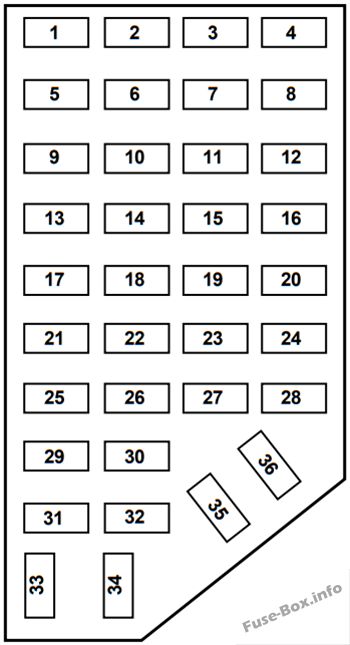
Assignment of the fuses in the Passenger compartment (1998)
| № | Amp Rating | Description |
|---|---|---|
| 1 | 7.5A | Power Mirror Switch, Power Antenna |
| 2 | 7.5A | Blower Motor Relay, Air Bag Diagnostic Monitor |
| 3 | 7.5A | Left Stop/Turn Trailer Tow Connector |
| 4 | 10A | Left Headlamp |
| 5 | 10A | Data Link Connector (DLC) |
| 6 | 7.5A | Rear Blower Motor (Without EATC) |
| 7 | 7.5A | Right Stop/Turn Trailer Tow Connector |
| 8 | 10A | Right Headlamp, Foglamp Relay |
| 9 | 7.5A | Brake Pedal Position Switch |
| 10 | 7.5A | Speed Control/Amplifier Assembly, Brake Pressure Switch, Generic electronic Module (GEM), Shift Lock Actuator, Blend Door Actuator, A IC – Heater Assembly, Flasher |
| 11 | 7.5A | Instrument Cluster |
| 12 | 7.5A | Power Windows Relay, Washer Pump Relay |
| 13 | 20A | Brake Pedal Position Switch, Brake Pressure Switch |
| 14 | 10A | 4 Wheel Anti-Lock Brake System (4WABS) Module, 4WABS Main Relay |
| 15 | 7.5A | Instrument Cluster |
| 16 | 30A | Windshield Wiper Motor, Wiper Hi-Lo Relay, Wiper Run/Park Relay |
| 17 | 25A | Cigar Lighter |
| 18 | 25A | Drivers Unlock Relay, All Unlock Relay, All Lock Relay |
| 19 | 25A | PCM Power Diode |
| 20 | 7.5A | RAP Module, Generic Electronic Module (GEM), Radio, Cellular Phone |
| 21 | 15A | Flasher (Hazard) |
| 22 | 20A | Auxiliary Power Socket |
| 23 | – | NOT USED |
| 24 | 7.5A | Clutch Pedal Position (CPP) Switch, Starter Interrupt Relay, Anti-Theft |
| 25 | 7.5A | Generic Electronic Module (GEM), Instrument Cluster, Securi-Lock |
| 26 | 10A | Battery Saver Relay, Electronic Shift Relay, Interior Lamp Relay, Power Window Relay, Electronic Shift Control Module |
| 27 | 15A | DRL, Backup Lamps Switch, DTR Sensor, GEM, Electric Shift |
| 28 | 7.5A | Generic Electronic Module (GEM), Radio, Memory Seat |
| 29 | 25A | Radio |
| 30 | 15A | Park Lamp/Trailer Tow Relay |
| 31 | – | NOT USED |
| 32 | 10A | Heated Mirror |
| 33 | 15A | Headlamps, Daytime Running Lamps (DRL) Module, Instrument Cluster |
| 34 | 7.5A | Rear Integrated Control Panel, CD |
| 35 | 7.5A | Rear Blower Motor (With EATC) |
| 36 | 7.5A | EATC Memory, CD, Rear Integrated Control Panel, Memory Seat, Message Center |
Engine compartment
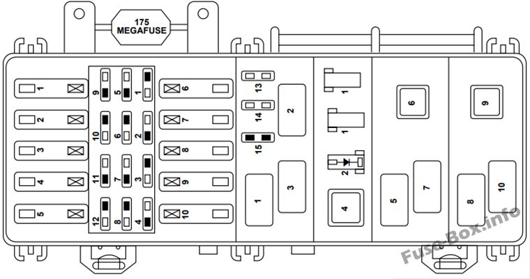
Assignment of the fuses in the Power distribution box (1998)
| № | Amp Rating | Description |
|---|---|---|
| 1 | 60A** | I/P Fuse Panel |
| 2 | 40A** | Blower Motor Relay |
| 3 | 50A** | 4 Wheel Anti-Lock Brake System (4WABS) Module |
| 4 | 30A** | Power Windows, Power Moon Roof, Power Seat |
| 5 | 50A** | Ignition Switch, Starter Relay |
| 6 | 20A** | Transfer Case Relay |
| 7 | — | NOT USED |
| 8 | 20A** | Automatic Ride Control ARC Switch OfPOn Switch |
| 9 | 40A** | Automatic Ride Control Relay |
| 10 | 30A** | PCM Power Relay |
| 1 | 10 A* | A/C Relay |
| 2 | – | NOT USED |
| 3 | 30 A* | Heated Backlight |
| 4 | 15A* | Fog Lamps and Daytime Running Lamps |
| 5 | 10 A* | Air Bag Diagnostic Monitor |
| 6 | 10 A* | Powertrain Control Module |
| 7 | 30 A* | 4 Wheel Anti-Lock System (4WABS) Module |
| 8 | 15A* | Rear Wiper Motor |
| 9 | 20 A* | Fuel Pump Relay and RAP Module |
| 10 | 15A* | Horn Relay |
| 11 | 15A* | Parklamps Relay and Mainlight Switch |
| 12 | 30 A* | Mainlight Switch and Multifunction Switch |
| 13 | 15A* | Heated Oxygen Sensor, EGR Vacuum Regulator, EVR Solenoid, Camshaft Position (CMP) Sensor, Canister Vent Solenoid |
| 14 | 30 A* | Generator/Voltage Regulator |
| 15 | – | NOT USED |
| Relay | ||
| 1 | – | Wiper Park Relay |
| 2 | – | A/C Relay |
| 3 | – | Wiper High/Low Relay |
| 4 | – | PCM Power Relay |
| 5 | – | Fuel Pump Relay |
| 6 | – | Starter Relay |
| 7 | – | Horn Relay |
| 8 | – | Rear Wipe Down Relay |
| 9 | – | Blower Motor Relay |
| 10 | – | Rear Wipe Up Relay |
| Diode | ||
| 1 | – | NOT USED |
| 1 | – | NOT USED |
| 2 | – | Electronic Engine Controls Diode |
| * Mini Fuses ** Maxi Fuses | ||
1999
Passenger compartment
Assignment of the fuses in the Passenger compartment (1999)
| № | Amp Rating | Description |
|---|---|---|
| 1 | 7.5A | Power Mirror Switch, Power Antenna |
| 2 | 7.5A | Blower Motor Relay, Air Bag Diagnostic Monitor |
| 3 | 7.5A | Left Stop/Turn Trailer Tow Connector |
| 4 | 10A | Left Headlamp |
| 5 | 10A | Data Link Connector (DLC) |
| 6 | 7.5A | Rear Blower Motor (Without EATC) |
| 7 | 7.5A | Right Stop/Turn Trailer Tow Connector |
| 8 | 10A | Right Headlamp, Foglamp Relay |
| 9 | 7.5A | Brake Pedal Position Switch |
| 10 | 7.5A | Speed Control/Amplifier Assembly, Generic electronic Module (GEM), Shift Lock Actuator, Blend Door Actuator, A/C – Heater Assembly, Flasher, Overhead Console, Load Leveling Module |
| 11 | 7.5A | Instrument Cluster |
| 12 | 7.5A | Washer Pump Relay, Rear Washer Pump Relay |
| 13 | 20A | Brake Pedal Position Switch, Brake Pressure Swatch |
| 14 | 10A | 4 Wheel Anti-Lock Brake System (4WABS) Module, 4WABS Main Relay |
| 15 | 7.5A | Instrument Cluster |
| 16 | 30A | Windshield Wiper Motor, Wiper Hi-Lo Relay, Wiper Run/Park Relay |
| 17 | 25A | Cigar Lighter |
| 18 | 25A | Drivers Unlock Relay, All Unlock Relay, All Lock Relay |
| 19 | 25A | PCM Power Diode |
| 20 | 7.5A | RAP Module, Generic Electronic Module (GEM), Radio |
| 21 | 15A | Flasher (Hazard) |
| 22 | 20A | Auxiliary Power Socket |
| 23 | — | Not Used |
| 24 | 7.5A | Clutch Pedal Position (CPP) Switch, Starter Interrupt Relay, Anti-Theft |
| 25 | 7.5A | Generic Electronic Module (GEM), Instrument Cluster, Securi-Lock |
| 26 | 10A | Battery Saver Relay, Electronic Shift Relay, Interior Lamp Relay, Electronic Shift Control Module |
| 27 | 15A | DRL, Backup Lamps Switch, DTR Sensor, Electric Shift |
| 28 | 7.5A | Generic Electronic Module (GEM), Radio, Memory Seat |
| 29 | 10A | Radio |
| 30 | 15A | Park Lamp/Trailer Tow Relay |
| 31 | — | Not Used |
| 32 | 10A | Heated Mirror |
| 33 | 15A | Headlamps, Daytime Running Lamps (DRL) Module, Instrument Cluster |
| 34 | 7.5A | Rear Integrated Control Panel, CD |
| 35 | 7.5A | Rear Blower Motor (w/EATC) |
| 36 | 7.5A | EATC Memory, CD, Rear Integrated Control Panel, Memory Seat, Message Center |
Engine compartment
Assignment of the fuses in the Power distribution box (1999)
| № | Amp Rating | Description |
|---|---|---|
| 1 | 60A** | I/P Fuse Panel |
| 2 | 40A** | Blower Motor Relay |
| 3 | 50A** | 4 Wheel Anti-Lock Brake System (4WABS) Module |
| 4 | 30A** | Power Windows, Power Moon Roof, Power Seat |
| 5 | 50A** | Ignition Switch, Starter Relay |
| 6 | 20A** | Transfer Case Relay |
| 7 | — | Not Used |
| 8 | 20A** | Automatic Ride Control ARC Switch Off/On Swatch |
| 9 | 40A** | Automatic Ride Control Relay |
| 10 | 30A** | PCM Power Relay |
| 1 | 10 A* | A/C Relay |
| 2 | 30A* | Heated Seats |
| 3 | 30A* | Heated Backlight |
| 4 | 15 A* | Fog Lamps and Daytime Running Lamps |
| 5 | — | Not Used |
| 6 | 10 A* | Powertrain Control Module |
| 7 | 30A* | 4 Wheel Anti-Lock System (4WABS) Module |
| 8 | 15 A* | Rear Wiper Motor |
| 9 | 20 A* | Fuel Pump Relay and RAP Module |
| 10 | 15 A* | Horn Relay |
| 11 | 15 A* | Parklamps Relay and Mainlight Switch |
| 12 | 30A* | Mainlight Switch and Multifunction Switch |
| 13 | 15 A* | Heated Oxygen Sensor, EGR Vacuum Regulator, EVR Solenoid, Camshaft Position (CMP) Sensor, Canister Vent Solenoid |
| 14 | 30A* | GeneratorAfoltage Regulator |
| 15 | — | Not Used |
| 1 | — | Wiper Park Relay |
| 2 | — | A/C Relay |
| 3 | — | Wiper High/Low Relay |
| 4 | — | PCM Power Relay |
| 5 | — | Fuel Pump Relay |
| 6 | — | Starter Relay |
| 7 | — | Horn Relay |
| 8 | — | Rear Wipe Down Relay |
| 9 | — | Blower Motor Relay |
| 10 | — | Rear Wipe Up Relay |
| 1 | — | Not Used |
| 1 | — | Not Used |
| 2 | — | Electronic Engine Controls Diode |
| * Mini Fuses ** Maxi Fuses |
2000
Passenger compartment
Assignment of the fuses in the Passenger compartment (2000)
| № | Amp Rating | Passenger Compartment Fuse Panel Description |
|---|---|---|
| 1 | 7.5A | Power Mirror Switch, Power Antenna, Memory 7 Seat |
| 2 | 7.5A | Blower Motor Relay, Air Bag Diagnostic Monitor |
| 3 | 7.5A | Left Stop/Turn Trailer Tow Connector |
| 4 | 10A | Left Headlamp |
| 5 | 10A | Data Link Connector (DLC) |
| 6 | 7.5A | Rear Blower Motor (Without EATC) |
| 7 | 7.5A | Right Stop/Turn Trailer Tow Connector |
| 8 | 10A | Right Headlamp, Foglamp Relay |
| 9 | 7.5A | Brake Pedal Position Switch |
| 10 | 7.5A | Speed Control/Amplifier Assembly, Generic electronic Module (GEM), Shift Lock Actuator, Blend Door Actuator, A/C – Heater Assembly, Flasher, Overhead Console, Load Leveling Module |
| 11 | 7.5A | Instrument Cluster |
| 12 | 7.5A | Washer Pump Relay, Rear Washer Pump Relay |
| 13 | 20A | Brake Pedal Position Switch, Brake Pressure Switch |
| 14 | 10A | 4 Wheel Anti-Lock Brake System (4WABS) Module, 4WABS Main Relay |
| 15 | 7.5A | Instrument Cluster |
| 16 | 30A | Windshield Wiper Motor, Wiper Hi-Lo Relay, Wiper Run/Park Relay |
| 17 | 25A | Cigar Lighter |
| 18 | 25A | Drivers Unlock Relay, All Unlock Relay, All Lock Relay, Power Seats |
| 19 | 25A | PCM Power Diode |
| 20 | 7.5A | RAP Module, Generic Electronic Module (GEM), Radio |
| 21 | 15A | Flasher (Hazard) |
| 22 | 20A | Auxiliary Power Socket |
| 23 | — | Not Used |
| 24 | 7.5A | Clutch Pedal Position (CPP) Switch, Starter Interrupt Relay, Anti-Theft |
| 25 | 7.5A | Generic Electronic Module (GEM), Instrument Cluster, Securi-Lock |
| 26 | 10A | Battery Saver Relay, Electronic Shift Relay, Interior Lamp Relay, Electronic Shift Control Module |
| 27 | 15A | DRL, Backup Lamps Swatch, DTR Sensor, Electric Shift |
| 28 | 7.5A | Generic Electronic Module (GEM), Radio, Memory Seat |
| 29 | 25A | Radio |
| 30 | 15A | Park Lamp/Trailer Tow Relay |
| 31 | — | Not Used |
| 32 | 10A | Heated Mirror |
| 33 | 15A | Headlamps, Daytime Running Lamps (DRL) Module, Instrument Cluster |
| 34 | 7.5A | Rear Integrated Control Panel, CD |
| 35 | 7.5A | Rear Blower Motor (w/EATC) |
| 36 | 7.5A | EATC Memory, CD, Rear Integrated Control Panel, Memory Seat, Message Center |
Engine compartment
Assignment of the fuses in the Power distribution box (2000)
| № | Amp Rating | Power Distribution Box Description |
|---|---|---|
| 1 | 60A** | I/P Fuse Panel |
| 2 | 40 A** | Blower Motor Relay |
| 3 | 50A** | 4 Wheel Anti-Lock Brake System (4WABS) Module |
| 4 | 30A** | Power Windows, Power Moon Roof, Power Seat |
| 5 | 50A** | Ignition Switch, Starter Relay |
| 6 | 20A** | Transfer Case Relay |
| 7 | — | Not Used |
| 8 | 20A** | Air Suspension |
| 9 | 40 A** | Air Suspension |
| 10 | 30A** | PCM Power Relay |
| 1 | 10 A* | A/C Relay |
| 2 | 30A* | Heated Seats |
| 3 | 30A* | Heated Backlight |
| 4 | 15A* | Fog Lamps and Daytime Running Lamps |
| 5 | — | Not Used |
| 6 | 10 A* | Powertrain Control Module |
| 7 | 30A* | 4 Wheel Anti-Lock System (4WABS) Module |
| 8 | 15A* | Rear Wiper Motor |
| 9 | 20A* | Fuel Pump Relay and RAP Module |
| 10 | 15A* | Horn Relay |
| 11 | 15A* | Parklamps Relay and Mainlight Switch |
| 12 | 30A* | Mainlight Switch and Multifunction Switch |
| 13 | 15A* | Heated Oxygen Sensor, EGR Vacuum Regulator, EVR Solenoid, Camshaft Position (CMP) Sensor, Canister Vent Solenoid |
| 14 | 30A* | Generator/Voltage Regulator |
| 15 | — | Not Used |
| 1 | — | Wiper Park Relay |
| 2 | — | A/C Relay |
| 3 | — | Wiper High/Low Relay |
| 4 | — | PCM Power Relay |
| 5 | — | Fuel Pump Relay |
| 6 | — | Starter Relay |
| 7 | — | Horn Relay |
| 8 | — | Rear Wipe Down Relay |
| 9 | — | Blower Motor Relay |
| 10 | — | Rear Wipe Up Relay |
| 1 | — | Not Used |
| 1 | — | DRL Diode |
| 2 | — | Electronic Engine Controls Diode |
| * Mini Fuses ** Maxi Fuses |
2001
Passenger compartment
Assignment of the fuses in the Passenger compartment (2001)
| № | Amp Rating | Description |
|---|---|---|
| 1 | 7.5A | Power Mirror Switch, Power Antenna, Memory Seat |
| 2 | 7.5A | Blower Motor Relay, Air Bag Diagnostic Monitor |
| 3 | 7.5A | Left Stop/Turn Trailer Tow Connector |
| 4 | 10A | Left Headlamp |
| 5 | 10A | Data Link Connector (DLC) |
| 6 | 7.5A | Rear Blower Motor (Without EATC) |
| 7 | 7.5A | Right Stop/Turn Trailer Tow Connector |
| 8 | 10A | Right Headlamp, Foglamp Relay |
| 9 | 7.5A | Brake Pedal Position Switch |
| 10 | 7.5A | Speed Control/Amplifier Assembly, Generic electronic Module (GEM), Shift Lock Actuator, Blend Door Actuator, A/C – Heater Assembly, Flasher, Overhead Console, Load Leveling Module |
| 11 | 7.5A | Instrument Cluster |
| 12 | 7.5A | Washer Pump Relay, Rear Washer Pump Relay |
| 13 | 20 A | Brake Pedal Position Switch, Brake Pressure Switch |
| 14 | 10A | 4 Wheel Anti-Lock Brake System (4WABS) Module, 4WABS Main Relay |
| 15 | 7.5A | Instrument Cluster |
| 16 | 30A | Windshield Wiper Motor, Wiper Hi-Lo Relay, Wiper Run/Park Relay |
| 17 | 25A | Cigar Lighter |
| 18 | 25A | Drivers Unlock Relay, All Unlock Relay, All Lock Relay, Power Seats |
| 19 | 25A | PCM Power Diode |
| 20 | 7.5A | RAP Module, Generic Electronic Module (GEM), Radio |
| 21 | 15A | Flasher (Hazard) |
| 22 | 20 A | Auxiliary Power Socket |
| 23 | — | Not Used |
| 24 | 7.5A | Clutch Pedal Position (CPP) Switch, Starter Interrupt Relay, Anti-Theft |
| 25 | 7.5A | Generic Electronic Module (GEM), Instrument Cluster, Securi-Lock |
| 26 | 10A | Batteiy Saver Relay, Electronic Shift Relay, Interior Lamp Relay, Electronic Shift Control Module |
| 27 | 15A | DRL, Backup Lamps Switch, DTR Sensor, Electric Shift |
| 28 | 7.5A | Generic Electronic Module (GEM), Radio, Memory Seat |
| 29 | 25A | Radio |
| 30 | 15A | Park Lamp/Trailer Tow Relay |
| 31 | — | Not Used |
| 32 | 10A | Heated Mirror |
| 33 | 15A | Headlamps, Daytime Running Lamps (DRL) Module, Instrument Cluster |
| 34 | 7.5A | Rear Integrated Control Panel, CD |
| 35 | 7.5A | Rear Blower Motor (w/EATC) |
| 36 | 7.5A | EATC Memory, CD, Rear Integrated Control Panel, Memory Seat, Message Center |
Engine compartment
Assignment of the fuses in the Power distribution box (2001)
| № | Amp Rating | Power Distribution Box Description |
|---|---|---|
| 1 | 60A** | I/P Fuse Panel fuses 1, 9, and 13 |
| 2 | 40A** | Blower Motor Relay |
| 3 | 50A** | 4 Wheel Anti-Lock Brake System (4WABS) Module |
| 4 | 30A** | Power Moon Roof, Accessory Relay Delay |
| 5 | 50A** | Ignition Switch, Starter Relay |
| 6 | 20A** | Transfer Case Relay |
| 7 | — | Not Used |
| 8 | 20A** | Air Suspension |
| 9 | 40A** | Air Suspension |
| 10 | 30A** | PCM Power Relay |
| 1 | 10 A* | A/C Relay |
| 2 | 30A* | Heated Seats |
| 3 | 30A* | Heated Backlight |
| 4 | 15 A* | Fog Lamps and Daytime Running Lamps |
| 5 | — | Not Used |
| 6 | 10 A* | Powertrain Control Module |
| 7 | 30A* | 4 Wheel Anti-Lock System (4WABS) Module |
| 8 | 15 A* | Rear Wiper Motor |
| 9 | 20A* | Fuel Pump Relay and RAP Module |
| 10 | 15 A* | Horn Relay |
| 11 | 15 A* | Parklamps Relay and Mainlight Switch |
| 12 | 30A* | Mainlight Switch and Multifunction Switch |
| 13 | 15 A* | Heated Oxygen Sensor, EGR Vacuum Regulator, EVR Solenoid, Camshaft Position (CMP) Sensor, Canister Vent Solenoid |
| 14 | 30A* | GeneratorAfoltage Regulator |
| 15 | — | Not Used |
| 1 | — | Wiper Park Relay |
| 2 | — | A/C Relay |
| 3 | — | Wiper High/Low Relay |
| 4 | — | PCM Power Relay |
| 5 | — | Fuel Pump Relay |
| 6 | — | Starter Relay |
| 7 | — | Horn Relay |
| 8 | — | Rear Wipe Down Relay |
| 9 | — | Blower Motor Relay |
| 10 | — | Rear Wipe Up Relay |
| 1 | — | Not Used |
| 1 | — | DRL Diode |
| 2 | — | Electronic Engine Controls Diode |
| * Mini Fuses ** Maxi Fuses |


