


Fuse Layout Ford E-Series / Econoline 2002-2008
Contents

Cigar lighter (power outlet) fuses in the Ford E-Series are the fuses №23 (Cigar Lighter), №26 (Rear Power Point), №33 (E Traveler Power Point #2) and №39 (E Traveler Power Point #1) in the Instrument panel fuse box (2002-2003). Since 2004 – fuses №26 (Cigar lighter), №32 (Power point #1 (instrument panel)), №34 (Power point #3 (console), if equipped) and №40 (Power point #2 (2nd row seating position – driver side) / body B-pillar) in the Instrument panel fuse box.
Table of Contents
Fuse box location
Passenger compartment
The fuse panel is located below and to the left of the steering wheel by the brake pedal.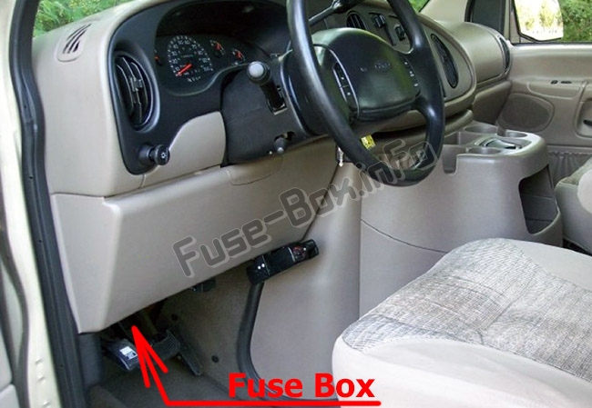
Engine compartment
The power distribution box is located in the engine compartment.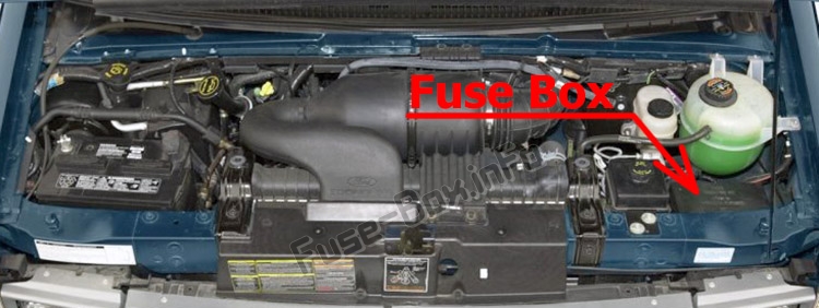
Relay modules:
Instrument panel relay module
The instrument panel relay module is located behind the radio in the center of the instrument panel
Engine compartment relay module
The engine compartment relay module is located in one of two places depending on which type of engine your vehicle is equipped with:
Gasoline engine: driver side of the engine compartment above the brake master cylinder.
Diesel engine: passenger side of the engine compartment behind the power distribution box.
Fuse box diagrams
2002
Passenger compartment
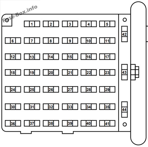
Assignment of the fuses in the Passenger compartment (2002)
| № | Amp Rating | Passenger Compartment Fuse Panel Description |
|---|---|---|
| 1 | 20A | 4WABS Module |
| 2 | 15A | Brake Warning Lamp, Instrument Cluster, Warning Chime, 4WABS Relay, Warning Indicators, Low Vacuum Warning Switch (Diesel Only) |
| 3 | 15A | Main Light Switch, RKE Module, Radio, Instrument Illumination, E Traveler VCP and video screens, Overhead Console |
| 4 | 15A | Power Locks w/RKE, Illuminated Entry, Warning Chime, Modified Vehicle, Main Light Switch, Courtesy Lamps |
| 5 | 20A | RKE Module, Power Lock Switches, Memory Lock, Power Locks with RKE |
| 6 | 10A | Brake Shift Interlock, Speed Control, DRL Module |
| 7 | 10A | Multi-Function Switch, Turn Signals |
| 8 | 30A | Radio Capacitor(s), Ignition Coil, PCM Diode, PCM Power Relay, Fuel Heater (Diesel Only), Glow Plug Relay (Diesel Only) |
| 9 | 30A | Wiper Control Module, Windshield Wiper Motor |
| 10 | 20A | Main Light Switch, Park Lamps, License Lamp,(External Lamps) Multi-Function Switch (Flash-to-pass) |
| 11 | 15A | Brake Pressure Switch, Multi-Function Switch (Hazards), Brake Lamp Switch, Brake Lamps |
| 12 | 15A | Transmission Range (TR) Sensor, Backup Lamps, Auxiliary Battery Relay |
| 13 | 15A | Blend Door Actuator, A/C Heater, Function Selector Switch |
| 14 | 5A | Instrument Cluster (Air Bag and Charge Indicator) |
| 15 | 5A | Trailer Battery Charge Relay |
| 16 | 30A | Power Seats |
| 17 | — | Not Used |
| 18 | — | Not Used |
| 19 | 10A | Air Bag Diagnostic Monitor |
| 20 | 5A | Overdrive Cancel Switch |
| 21 | 30A | Power Windows* |
| 22 | 15A | Memory Power Radio, E Traveler Radio, E Traveler Console |
| 23 | 20A | Cigar Lighter, Data Link Connector (DLC) |
| 24 | — | Not Used |
| 25 | 10A | Left Headlamp (Low Beam) |
| 26 | 20A | Rear Power Point |
| 27 | 5A | Radio |
| 28 | 20A | Power Plug |
| 29 | — | Not Used |
| 30 | 15A | Headlamps (High Beam Indicator), DRL10A |
| 31 | 10A | Right Headlamp (Low Beam), DRL |
| 32 | 5A | Power Mirrors |
| 33 | 20A | E Traveler Power Point #2 |
| 34 | 10A | Transmission Range (TR) Sensor |
| 35 | 30A | RKE Module |
| 36 | 5A | (Cluster, A/C, Illumination, Radio), Steering Column Assembly |
| 37 | 20A | Power Plug |
| 38 | 10A | Air Bag Diagnostic Monitor |
| 39 | 20A | E Traveler Power Point #1 |
| 40 | 30A | Modified Vehicle |
| 41 | 30A | Modified Vehicle |
| 42 | — | Not Used |
| 43 | 20A C.B. | Power Windows* |
| 44 | — | Not Used |
| * Either Fuse 21 or Circuit breaker 43 will be present for power windows. |
Engine compartment
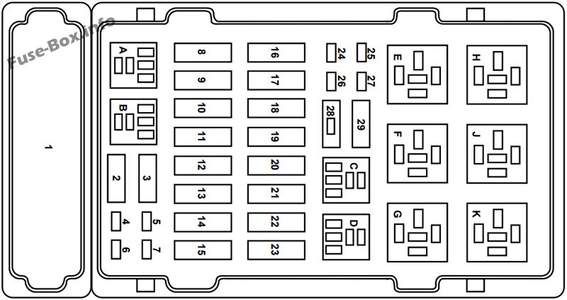
Assignment of the fuses in the Power distribution box (2002)
| № | Amp Rating | Power Distribution Box Description |
|---|---|---|
| 1 | — | Not Used |
| 2 | — | Not Used |
| 3 | — | Not Used |
| 4 | 10 A* | PCM Keep Alive Memory, Instrument Cluster, Voltmeter |
| 5 | 10 A* | Right Trailer Turn Signal |
| 6 | 10 A* | Left Trailer Turn Signal |
| 7 | — | Not Used |
| 8 | 60A** | I/P Fuses 5, 11, 23, 38, 4, 10, 16, 22, 28, 32 |
| 9 | 30A** | PCM Power Relay, Engine Compartment Fuse 4 |
| 10 | 60A** | Auxiliary Battery Relay, Engine Compartment Fuses 14, 22 |
| 11 | 30A** | IDM Relay (Diesel Only) |
| 12 | 60A** | Engine Compartment Fuses 25, 27 |
| 13 | 50A** | Blower Motor Relay (Blower Motor) |
| 14 | 30A** | Trailer Running Lamps Relay, Trailer Backup Lamps Relay |
| 15 | 40A** | Main Light Switch, Daytime Running Lights (DRL) |
| 16 | 50A** | Auxiliary Blower Motor Relay |
| 17 | 30A** | Fuel Pump Relay |
| 18 | 60A** | I/P Fuses 40, 41,26, 33, 39 |
| 19 | 60A** | 4WABS Module |
| 20 | 20A** | Electric Brake Controller |
| 21 | 50A** | Modified Vehicle Power |
| 22 | 40A** | Trailer Battery Charge Relay, Modified Vehicles |
| 23 | 60A** | Ignition Switch, Fuse Panel |
| 24 | 20A* | Natural Gas Tank Valves (NGV only) |
| 25 | 20A* | NGV Module (Natural Gas Only) |
| 26 | 10 A* | A/C Clutch (4.2L Only) |
| 27 | 15A* | DRL Module, Horn Relay |
| 28 | — | PCM Diode |
| 29 | — | Not Used |
| A | — | Not Used |
| B | — | Stop Lamp Relay |
| C | — | Trailer Backup Lamps Relay |
| D | — | Trailer Running Lamps Relay |
| E | — | Trailer Battery Charge Relay |
| F | — | IDM Relay (Diesel Only), A/C Clutch Relay (4.2L Only) |
| G | — | PCM Relay |
| H | — | Blower Motor Relay |
| J | — | Horn Relay |
| K | — | Fuel Pump Relay |
| * Mini Fuses ** Maxi Fuses |
2003
Passenger compartment
Assignment of the fuses in the Passenger compartment (2003)
| № | Amp Rating | Passenger Compartment Fuse Panel Description |
|---|---|---|
| 1 | 20A | 4WABS module |
| 2 | 15A | Brake warning lamp, Instrument cluster, Warning chime, 4WABS relay, Warning indicators, Low vacuum warning switch (Diesel only) |
| 3 | 15A | Main light switch, RKE module, Radio, Instrument illumination, VCP and video screens, Overhead console |
| 4 | 15A | Power locks w/RKE, Illuminated entry, Warning chime, Modified vehicle, Main light switch, Courtesy lamps |
| 5 | 20A | RKE module, Power lock switches, Memory lock, Power locks with RKE |
| 6 | 10A | Brake shift interlock, Speed control, DRL module |
| 7 | 10A | Multi-function switch, Turn signals |
| 8 | 30A | Radio capacitor(s), Ignition coil, PCM diode, PCM power relay, Fuel heater (Diesel only), Glow plug relay (Diesel only) |
| 9 | 30A | Wiper control module, Windshield wiper motor |
| 10 | 20A | Main light switch, Park lamps, License lamp (external lamps), Multi-function switch (flash-to-pass) |
| 11 | 15A | Brake pressure switch, Multi-function switch (hazards), Brake lamp switch, Brake lamps |
| 12 | 15A | Transmission Range (TR) sensor, Backup lamps, Auxiliary battery relay |
| 13 | 15A | Blend door actuator, A/C heater, Function selector switch |
| 14 | 5A | Instrument cluster (air bag and charge indicator) |
| 15 | 5A | Trailer battery charge relay |
| 16 | 30A | Power seats |
| 17 | — | Not used |
| 18 | — | Not used |
| 19 | 10A | Air bag diagnostic monitor |
| 20 | 5A | Overdrive cancel switch |
| 21 | 30A | Power windows* |
| 22 | 15A | Memory power radio, Rear seat control unit, Video screen |
| 23 | 20A | Cigar lighter, Data Link Connector (DLC) |
| 24 | — | Not used |
| 25 | 10A | Left headlamp (low beam) |
| 26 | — | Not used |
| 27 | 5A | Radio |
| 28 | 20A | Power plug |
| 29 | — | Not used |
| 30 | 15A | Headlamps (high beam indicator), DRL10A |
| 31 | 10A | Right Headlamp (Low Beam), DRL |
| 32 | 5A | Power mirrors |
| 33 | 20A | Power point #2 |
| 34 | 10A | Transmission Range (TR) sensor |
| 35 | 30A | RKE module |
| 36 | 5A | (Cluster, A/C, Illumination, Radio), Steering column assembly |
| 37 | 20A | Rear power point |
| 38 | 10A | Air bag diagnostic monitor |
| 39 | 20A | Power point #1 |
| 40 | 30A | Modified vehicle |
| 41 | 30A | Modified vehicle |
| 42 | — | Not used |
| 43 | 20A C.B. | Power windows* |
| 44 | — | Not used |
| * Either Fuse 21 or Circuit breaker 43 will be present for power windows. |
Engine compartment
Assignment of the fuses in the Power distribution box (2003)
| № | Amp Rating | Power Distribution Box Description |
|---|---|---|
| 1 | — | Not used |
| 2 | — | Not used |
| 3 | — | Not used |
| 4 | 10 A* | Powertrain Control Module (PCM) Keep Alive Memory, Instrument cluster, Voltmeter |
| 5 | 10 A* | Right trailer turn signal |
| 6 | 10 A* | Left trailer turn signal |
| 7 | 20A* | Clearance lamps |
| 8 | 60A** | I/P fuses 4, 5, 10, 11, 16, 22, 23, 28, 32, 38 |
| 9 | 30A** | PCM power relay, Engine compartment fuse 4 |
| 10 | 60A** | Auxiliary battery relay, Engine compartment fuses 14, 22 |
| 11 | 30A** | IDM relay (Diesel only) |
| 12 | 60A** | Engine compartment fuses 25, 27 |
| 13 | 50A** | Blower motor relay (blower motor) |
| 14 | 30A** | Trailer running lamps relay, Trailer backup lamps relay |
| 15 | 40 A** | Main light switch, Daytime Running Lights (DRL) |
| 16 | 50A** | Auxiliary blower motor relay |
| 17 | 30A** | Fuel pump relay |
| 18 | 60A** | I/P fuses 33, 37, 39, 40, 41 |
| 19 | 60A** | 4WABS module |
| 20 | 20A** | Electric brake controller |
| 21 | 50A** | Modified vehicle power |
| 22 | 40 A** | Trailer battery charge relay, Modified vehicles |
| 23 | 60A** | Ignition switch, Fuse panel |
| 24 | 30A* | Natural gas tank valves (NGV only) |
| 25 | 20A* | NGV module (NGV only) |
| 26 | 10 A* | A/C clutch (4.2L only) |
| 27 | 15A* | DRL module, Horn relay |
| 28 | — | PCM diode |
| 29 | — | Not used |
| A | — | Marker lamps relay |
| B | — | Stop lamp relay |
| C | — | Trailer backup lamps relay |
| D | — | Trailer running lamps relay |
| E | — | Trailer battery charge relay |
| F | — | IDM relay (Diesel only), A/C clutch relay (4.2L only) |
| G | — | PCM relay |
| H | — | Blower motor relay |
| J | — | Horn relay |
| K | — | Fuel pump relay |
| * Mini fuses ** Maxi fuses |
2004
Passenger compartment
Assignment of the fuses in the Passenger compartment (2004)
| № | Amp Rating | Passenger Compartment Fuse Panel Description |
|---|---|---|
| 1 | 5A | 4-Wheel Anti-lock Brake System (4WABS) module |
| 2 | 10A | Remote Keyless Entry (RKE), O/D cancel, Low vacuum (Diesel engine only) |
| 3 | 15A | Trip computer, Radio, Instrument illumination, Video Cassette Player (VCP) and video screens, Overhead console |
| 4 | 15A | Modified vehicle, Courtesy lamps |
| 5 | 30A | Power lock switches, Power locks without RKE |
| 6 | 10A | Brake-shift interlock, Speed control (gasoline engine only) |
| 7 | 10A | Multi-function switch, Turn signals |
| 8 | 30A | Radio capacitor(s), Ignition coil, Powertrain Control Module (PCM) diode, PCM power relay, Auxiliary PCM (APCM) (Diesel engine only) |
| 9 | 30A | Wiper control module, Windshield wiper motor |
| 10 | 20A | Main light switch, Park lamps, License lamp (external lamps), Multi-function switch (flash-to-pass) |
| 11 | 15A | Multi-function switch (hazards), Brake lamp switch, Brake lamps |
| 12 | 15A | Back-up lamps, Auxiliary battery relay (gasoline engine only), Trailer tow relay |
| 13 | 15A | Blend door actuator, A/C heater, Function selector switch |
| 14 | 5A | Instrument cluster |
| 15 | 5A | Trailer battery charge relay, Cluster, Daytime Running Lamps (DRL) module |
| 16 | 30A | Power seats |
| 17 | 5A | Power mirrors |
| 18 | — | Not used |
| 19 | — | Not used |
| 20 | 10A | Restraints |
| 21 | — | Not used |
| 22 | 15A | Memory power radio, Rear seat video control unit, Batteiy saver relay, Instrument cluster, Courtesy lamp relay, Accessory delay relay |
| 23 | 20A | Power locks w/RKE |
| 24 | — | Not used |
| 25 | 10A | Left headlamp (low beam) |
| 26 | 20A | Cigar lighter, Diagnostics |
| 27 | 5A | Radio |
| 28 | — | Not used |
| 29 | 20A | Power point #4 (console) |
| 30 | 15A | Headlamps (high beam indicator) |
| 31 | 10A | Right headlamp (low beam) |
| 32 | 20A | Power point #1 (instrument panel) |
| 33 | 10A | Starter solenoid (gasoline engine only)/Start relay (diesel engine only) |
| 34 | 20A | Power point #3 (console) |
| 35 | 30A | Modified vehicle |
| 36 | 5A | (Cluster, A/C, Illumination, Radio) |
| 37 | — | Not used |
| 38 | — | Not used |
| 39 | 10A | Trailer tow electric brake, Center High-Mounted Stop Lamp (CHMSL), Brake lamps |
| 40 | 20A | Power point #2 (2nd row seating position – driver side) |
| 41 | 30A | Modified vehicle |
| 42 | — | Not used |
| 43 | 20A circuit breaker | Power windows |
| 44 | — | Not used |
Engine compartment
Assignment of the fuses in the Power distribution box (2004)
| № | Amp Rating | Power Distribution Box Description |
|---|---|---|
| 1 | — | Powertrain Control Module (PCM) diode |
| 2 | Alternative Fuel Control Module (AFCM) diode (Natural gas vehicle only) | |
| 3 | 10 A* | Daytime Running Lamps (DRL) module, A/C clutch |
| 4 | 20 A* | Natural Gas Vehicle (NGV) tank solenoids (natural gas vehicle only) |
| 5 | 15 A* | Horn relay |
| 6 | 2A* | Brake pressure switch |
| 7 | 60A** | Ignition switch, Fuse panel, Accessory delay |
| 8 | 40A** | Trailer battery charge relay |
| 9 | 50A** | Modified vehicle power |
| 10 | 30A** | Electric brake controller |
| 11 | 60A** | 4-Wheel Anti-lock Brake System (4WABS) |
| 12 | 60A** | I/P fuses 29, 34, 35, 40 and 41 |
| 13 | 20A** | Fuel pump relay |
| 14 | 50A** | Auxiliary blower relay |
| 15 | 30A** | Main light switch |
| 16 | — | Not used |
| 17 | 50A** | Blower motor relay (blower motor) |
| 18 | 60A** | Engine compartment fuses 3, 5, 23 and 26, Instrument panel fuses 26 and 32, Diesel start relay (Diesel engine only) |
| 19 | 50A** | IDM relay (Diesel engine only) |
| 20 | 60A** | Auxiliary battery relay (gasoline engine only), PDB fuses 8 and 24 (Diesel engine only) |
| 21 | 30A** | PCM power relay, PDB fuse 27 |
| 22 | 60A** | I/P fuses 4, 5, 10, 11, 16, 17, 22 and 23 |
| 23 | 10 A* | Alternator |
| 24 | 20 A* | Trailer tow running lamps and back-up lamp relays |
| 25 | — | Not used |
| 26 | 20 A* | Trailer tow turn signals |
| 27 | 10 A* | PCM |
| 28 | — | Not used |
| A | — | Fuel pump relay |
| B | — | Horn relay |
| C | — | Trailer back-up lamps relay |
| D | — | Trailer running lamps relay |
| E | — | Trailer battery charge relay |
| F | — | IDM relay (Diesel only) |
| G | — | PCM relay |
| H | — | Blower motor relay |
| J | — | Accessory delay relay |
| K | — | Start relay (Diesel only) |
| * Mini fuses ** Maxi fuses |
Instrument panel relay module (2004)
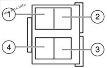
| Relay location | Description |
|---|---|
| 1 | Interior lamps |
| 2 | Open |
| 3 | Roof marker lamps |
| 4 | Battery saver |
Engine compartment relay module (2004)
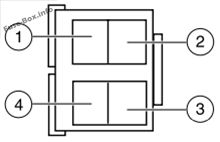
| Relay location | Description |
|---|---|
| 1 | Trailer tow left turn |
| 2 | A/C control |
| 3 | PCM back-up lamp |
| 4 | Trailer tow right turn |
2005
Passenger compartment
Assignment of the fuses in the Passenger compartment (2005)
| № | Amp Rating | Passenger Compartment Fuse Panel Description |
|---|---|---|
| 1 | 5A | 4-Wheel Anti-lock Brake System (4WABS) module |
| 2 | 10A | Remote Keyless Entry (RKE), O/D cancel |
| 3 | 15A | Trip computer, Radio, Video Cassette Player (VCP) and video screens, Overhead console |
| 4 | 15A | Courtesy lamps |
| 5 | 30A | Power lock switches, Power locks without RKE |
| 6 | 10A | Brake-shift interlock, Daytime Running Lamps (DRL) module |
| 7 | 10A | Multi-function switch, Turn signals |
| 8 | 30A | Radio capacitor(s), Ignition coil, Powertrain Control Module (PCM) diode, PCM power relay |
| 9 | 5A | Wiper control module |
| 10 | 20A | Main light switch, Park lamps, License lamp (external lamps), Multi-function switch (flash-to-pass) |
| 11 | 15A | Multi-function switch (hazards), Brake lamp switch, Brake lamps |
| 12 | 15A | Back-up lamps, Auxiliary battery relay (gasoline engine only), Trailer tow relay |
| 13 | 15A | Blend door actuator, Function selector switch |
| 14 | 5A | Instrument cluster |
| 15 | 5A | Trailer battery charge relay, Cluster |
| 16 | 30A | Power seats |
| 17 | 5A | Power mirrors |
| 18 | — | Not used |
| 19 | — | Not used |
| 20 | 10A | Restraints |
| 21 | — | Not used |
| 22 | 15A | Memory power radio, Rear seat video control unit, Batteiy saver relay, Instrument cluster, Courtesy lamp relay, Accessory delay relay |
| 23 | 20A | Power locks w/RKE |
| 24 | — | Not used |
| 25 | 10A | Left headlamp (low beam) |
| 26 | 20A | Cigar lighter, Diagnostics |
| 27 | 5A | Radio |
| 28 | — | Not used |
| 29 | — | Not used |
| 30 | 15A | Headlamps (high beam indicator) |
| 31 | 10A | Right headlamp (low beam) |
| 32 | 20A | Power point #1 (instrument panel) |
| 33 | 10A | Start relay |
| 34 | — | Not used |
| 35 | — | Not used |
| 36 | 5A | Instrument illumination |
| 37 | — | Not used |
| 38 | — | Not used |
| 39 | 10A | Trailer tow electric brake, Center High-Mounted Stop Lamp (CHMSL), Brake lamps |
| 40 | 20A | Power point #2 (2nd row seating position – driver side) |
| 41 | 30A | Modified vehicle |
| 42 | 20A circuit breaker | Power windows |
| 43 | — | Not used |
| 44 | 20A circuit breaker | Wiper/washer |
Engine compartment
Assignment of the fuses in the Power distribution box (2005)
| № | Amp Rating | Power Distribution Box Description |
|---|---|---|
| 1 | — | Powertrain Control Module (PCM) diode |
| 2 | — | Not used |
| 3 | 10 A* | Daytime Running Lamps (DRL) module, A/C clutch |
| 4 | — | Not used |
| 5 | 15 A* | Horn relay |
| 6 | 2A* | Brake pressure switch |
| 7 | 60A** | Ignition switch, Fuse panel, Accessory delay |
| 8 | 40A** | Trailer battery charge relay |
| 9 | 50A** | Modified vehicle power |
| 10 | 30A** | Electric brake controller |
| 11 | 60A** | 4-Wheel Anti-lock Brake System (4WABS) |
| 12 | 60A** | I/P fuses 29, 34, 35, 40 and 41 |
| 13 | 20A** | Fuel pump relay |
| 14 | 50A** | Auxiliary blower relay |
| 15 | 30A** | Main light switch |
| 16 | — | Not used |
| 17 | 50A** | Blower motor relay (blower motor) |
| 18 | 60A** | Engine compartment fuses 3, 5, 23 and 26, Instrument panel fuses 26 and 32, Start relay |
| 19 | 50A** | IDM relay (Diesel engine only) |
| 20 | 60A** | Auxiliary battery relay (gasoline engine only), PDB fuses 8 and 24 |
| 21 | 30A** | PCM power relay, PDB fuse 27 |
| 22 | 60A** | I/P fuses 4, 5, 10, 11, 16, 17, 22 and 23, Circuit breaker 44 |
| 23 | — | Not used |
| 24 | 20 A* | Trailer tow running lamps and back-up lamp relays |
| 25 | — | Not used |
| 26 | 20 A* | Trailer tow turn signals |
| 27 | 10 A* | PCM |
| 28 | — | Not used |
| A | — | Fuel pump relay |
| B | — | Horn relay |
| c | Trailer back-up lamps relay | |
| D | — | Trailer running lamps relay |
| E | — | Trailer battery charge relay |
| F | — | IDM relay (Diesel only) |
| G | — | PCM relay |
| H | — | Blower motor relay |
| J | — | Accessory delay relay |
| K | — | Start relay |
| * Mini fuses ** Maxi fuses |
Instrument panel relay module (2005)
| Relay location | Description |
|---|---|
| 1 | Interior lamps |
| 2 | Open |
| 3 | Open |
| 4 | Battery saver |
Engine compartment relay module (2005)
| Relay location | Description |
|---|---|
| 1 | PCM back-up lamp |
| 2 | A/C control |
| 3 | Trailer tow right turn |
| 4 | Trailer tow left turn |
2006
Passenger compartment
Assignment of the fuses in the Passenger compartment (2006)
| № | Amp Rating | Passenger Compartment Fuse Panel Description |
|---|---|---|
| 1 | 5A | 4-Wheel Anti-lock Brake System (4WABS) module |
| 2 | 10A | Remote Keyless Entry (RKE), O/D cancel, IVD module |
| 3 | 15A | Trip computer, Radio, Overhead console |
| 4 | 15A | Courtesy lamps |
| 5 | 30A | Power lock switches, Power locks without RKE |
| 6 | 10A | Brake-shift interlock, Daytime Running Lamps (DRL) module |
| 7 | 10A | Multi-function switch, Turn signals |
| 8 | 30A | Radio capacitor(s), Ignition coil, Powertrain Control Module (PCM) diode, PCM power relay |
| 9 | 5A | Wiper control module |
| 10 | 20A | Main light switch, Park lamps, License lamp (external lamps), Multi-function switch (flash-to-pass) |
| 11 | 15A | Multi-function switch (hazards), Brake lamp switch, Brake lamps |
| 12 | 15A | Back-up lamps, Auxiliary battery relay (gasoline engine only) |
| 13 | 15A | Blend door actuator, Function selector switch |
| 14 | 5A | Instrument cluster |
| 15 | 5A | Trailer battery charge relay, Cluster |
| 16 | 30A | Power seats |
| 17 | 5A | Power mirrors |
| 18 | — | Not used |
| 19 | — | Not used |
| 20 | 10A | Restraints |
| 21 | — | Not used |
| 22 | 15A | Memory power radio, Battery saver relay, Instrument cluster, Courtesy lamp relay, Accessory delay relay |
| 23 | 20A | Power locks w/RKE |
| 24 | — | Not used |
| 25 | 10A | Left headlamp (low beam) |
| 26 | 20A | Cigar lighter, Diagnostics |
| 27 | 5A | Radio |
| 28 | — | Not used |
| 29 | — | Not used |
| 30 | 15A | Headlamps (high beam indicator) |
| 31 | 10A | Right headlamp (low beam) |
| 32 | 20A | Power point #1 (instrument panel) |
| 33 | 10A | Start relay |
| 34 | 30A | IP Body builder connector #3 |
| 35 | — | Not used |
| 36 | 5A | Instrument illumination |
| 37 | 5A | Airbag deactivation switch |
| 38 | — | Not used |
| 39 | 10A | Trailer tow electric brake, Center High-Mounted Stop Lamp (CHMSL), Brake lamps |
| 40 | 20A | Power point #2 (2nd row seating position – driver side) |
| 41 | 30A | Modified vehicle |
| 42 | 20A circuit breaker | Power windows |
| 43 | — | Not used |
| 44 | 20A circuit breaker | Wiper/washer |
Engine compartment
Assignment of the fuses in the Power distribution box (2006)
| № | Amp Rating | Power Distribution Box Description |
|---|---|---|
| 1 | — | Powertrain Control Module (PCM) diode |
| 2 | — | Auxiliary battery diode |
| 3 | 15 A* | Daytime Running Lamps (DRL) module, A/C clutch |
| 4 | 5A* | Heated PCV (4.6L and 6.8L gasoline engines) |
| 5 | 15 A* | Horn relay |
| 6 | 2A* | Brake pressure switch |
| 7 | 60A** | Ignition switch, Accessory delay |
| 8 | 40A** | Trailer battery charge relay |
| 9 | 50A** | Modified vehicle power |
| 10 | 30A** | Electric brake controller |
| 11 | 60A** | 4-Wheel Anti-lock Brake System (4WABS) |
| 11 | 40A** | AdvanceTrac® with RSC |
| 12 | 60A** | I/P fuses 29, 34, 35, 40 and 41 |
| 13 | 20A** | Fuel pump relay |
| 14 | 50A** | Auxiliary blower relay |
| 15 | 30A** | Main light switch |
| 16 | 20A** | Injectors (gasoline engines) |
| 17 | 50A** | Blower motor relay (blower motor) |
| 18 | 60A** | Engine compartment fuses 3, 5 and 26, Instrument panel fuses 26 and 32, Start relay |
| 19 | 50A** | IDM relay (diesel engine only) |
| 19 | 40A** | AdvanceTrac® with RSC (gasoline engines only ) |
| 20 | 60A** | Auxiliary battery relay (gasoline engine only), PDB fuses 8 and 24 |
| 21 | 30A** | PCM power relay, PDB fuse 27 |
| 22 | 60A** | I/P fuses 4, 5, 10, 11, 16, 17, 22 and 23, Circuit breaker 44 |
| 23 | 10 A* | Alternator field (diesel engine only) |
| 23 | 20 A* | CMS, HEGOS, MAF, EGR, A/C clutch relay (gasoline engine only) |
| 24 | 20 A* | Trailer tow running lamps and back-up lamp relays |
| 25 | — | Not used |
| 26 | 20 A* | Trailer tow turn signals |
| 27 | 10 A* | PCM |
| 28 | — | Not used |
| A | — | Fuel pump relay |
| B | — | Horn relay |
| C | — | Trailer back-up lamps relay |
| D | — | Trailer running lamps relay |
| E | — | Trailer battery charge relay |
| F | — | IDM relay (diesel only), IVD (gasoline only) |
| G | — | PCM relay |
| H | — | Blower motor relay |
| J | — | Accessory delay relay |
| K | — | Start relay |
| * Mini fuses ** Maxi fuses |
Instrument panel relay module (2006)
| Relay location | Description |
|---|---|
| 1 | Interior lamps |
| 2 | Open |
| 3 | Open |
| 4 | Battery saver |
Engine compartment relay module (2006)
| Relay location | Description |
|---|---|
| 1 | PCM back-up lamp |
| 2 | A/C control |
| 3 | Trailer tow right turn |
| 4 | Trailer tow left turn |
2007
Passenger compartment
Assignment of the fuses in the Passenger compartment (2007)
| № | Amp Rating | Passenger Compartment Fuse Panel Description |
|---|---|---|
| 1 | 5A | 4-Wheel Anti-lock Brake System (4WABS) module |
| 2 | 10A | Remote Keyless Entry (RKE), O/D cancel, IVD module |
| 3 | 15A | Trip computer, Radio, Overhead console |
| 4 | 15A | Courtesy lamps |
| 5 | 30A | Power lock switches, Power locks without RKE |
| 6 | 10A | Brake-shift interlock, Daytime Running Lamps (DRL) module |
| 7 | 10A | Multi-function switch, Turn signals |
| 8 | 15A | Radio capacitor(s), Ignition coil, Powertrain Control Module (PCM) diode, PCM power relay |
| 9 | 5A | Wiper control module |
| 10 | 20A | Main light switch, Park lamps, License lamp (external lamps), Multi-function switch (flash-to-pass), BSM |
| 11 | 15A | Multi-function switch (hazards), Brake lamp switch, Brake lamps, IVD relay |
| 12 | 15A | Back-up lamps, Auxiliary battery relay (gasoline engine only) |
| 13 | 15A | Blend door actuator, Function selector switch |
| 14 | 5A | Instrument cluster |
| 15 | 5A | Trailer battery charge relay, Cluster, BSM |
| 16 | 30A | Power seats |
| 17 | 5A | Power mirrors |
| 18 | — | Not used |
| 19 | — | Not used |
| 20 | 10A | Restraints |
| 21 | — | Not used |
| 22 | 15A | Memory power radio, Battery saver relay, Instrument cluster, Courtesy lamp relay, Accessory delay relay |
| 23 | 20A | Power locks w/RKE |
| 24 | — | Not used |
| 25 | 10A | Left headlamp (low beam) |
| 26 | 20A | Cigar lighter, Diagnostics |
| 27 | 5A | Radio |
| 28 | — | Not used |
| 29 | — | Not used |
| 30 | 15A | Headlamps (high beam indicator) |
| 31 | 10A | Right headlamp (low beam) |
| 32 | 20A | Power point #1 (instrument panel) |
| 33 | 10A | Start relay |
| 34 | — | Not used |
| 35 | — | Not used |
| 36 | 5A | Instrument illumination |
| 37 | — | Not used |
| 38 | — | Not used |
| 39 | 10A | Trailer tow electric brake, Center High-Mounted Stop Lamp (CHMSL), Brake lamps |
| 40 | 20A | Power point #2 (2nd row seating position – driver side) |
| 41 | 30A | Modified vehicle |
| 42 | 20A circuit breaker | Power windows |
| 43 | — | Not used |
| 44 | 20A circuit breaker | Wiper/washer |
Engine compartment
Assignment of the fuses in the Power distribution box (2007)
| № | Amp Rating | Power Distribution Box Description |
|---|---|---|
| 1 | — | Powertrain Control Module (PCM) diode |
| 2 | — | Auxiliary battery diode |
| 3 | 15 A* | Daytime Running Lamps (DRL) module, A/C clutch |
| 4 | 5A* | Heated PCV (4.6L and 6.8L gasoline engines) |
| 5 | 15 A* | Horn relay |
| 6 | — | Not used |
| 7 | 60A** | Ignition switch, Accessory delay |
| 8 | 40A** | Trailer battery charge relay |
| 9 | 50A** | Modified vehicle power |
| 10 | 30A** | Electric brake controller |
| 11 | 60A** | 4-Wheel Anti-lock Brake System (4WABS) |
| 11 | 40A** | AdvanceTrac® with RSC |
| 12 | 60A** | I/P fuses 29, 34, 35, 40 and 41 |
| 13 | 20A** | Fuel pump relay |
| 14 | 50A** | Auxiliary blower relay |
| 15 | 30A** | Main light switch |
| 16 | 20A** | Injectors (gasoline engines) |
| 17 | 50A** | Blower motor relay (blower motor) |
| 18 | 60A** | Engine compartment fuses 3, 5 and 26, Instrument panel fuses 26 and 32, Start relay |
| 19 | 50A** | IDM relay (diesel engine only) |
| 19 | 40A** | AdvanceTrac® with RSC (gasoline engines only ) |
| 20 | 60A** | Auxiliary battery relay (gasoline engine only), PDB fuses 8 and 24 |
| 21 | 30A** | PCM power relay, PDB fuse 27 |
| 22 | 60A** | I/P fuses 4, 5, 10, 11, 16, 17, 22 and 23, Circuit breaker 44 |
| 23 | 10 A* | Alternator field (diesel engine only) |
| 23 | 20 A* | CMS, HEGOS, MAF, EGR, A/C clutch relay (gasoline engine only) |
| 24 | 20 A* | Trailer tow running lamps and back-up lamp relays |
| 25 | — | Not used |
| 26 | 20 A* | Trailer tow turn signals |
| 27 | 10 A* | PCM keep alive, Canister vent (gasoline engine only) |
| 28 | — | Not used |
| A | — | Fuel pump relay |
| B | — | Horn relay |
| C | — | Trailer back-up lamps relay |
| D | — | Trailer running lamps relay |
| E | — | Trailer battery charge relay |
| F | — | IDM relay (diesel only), IVD (gasoline only) |
| G | — | PCM relay |
| H | — | Blower motor relay |
| J | — | Accessory delay relay |
| K | — | Start relay |
| * Mini fuses ** Maxi fuses |
Instrument panel relay module (2007)
| Relay location | Description |
|---|---|
| 1 | Interior lamps |
| 2 | Open |
| 3 | Open |
| 4 | Battery saver |
Engine compartment relay module (2007)
| Relay location | Description |
|---|---|
| 1 | PCM back-up lamp |
| 2 | A/C control |
| 3 | Trailer tow right turn |
| 4 | Trailer tow left turn |
2008
Passenger compartment
Assignment of the fuses in the Passenger compartment (2008)
| № | Amp Rating | Description |
|---|---|---|
| 1 | — | Not used |
| 2 | 10A | Remote Keyless Entry (RKE), O/D cancel, IVD module, 4W ABS |
| 3 | 15A | Delayed accessoiy overhead console, Audio |
| 4 | 15A | Courtesy lamps |
| 5 | 30A | Power locks without RKE or sliding door |
| 6 | 10A | Daytime Running Lamps (DRL) module |
| 7 | 10A | Multi-function switch, Turn signals |
| 8 | 15A | Radio capacitor(s), Ignition coils, PCM (Powertrain Control Module) relay |
| 9 | 5A | Wiper control module |
| 10 | 20A | Main light switch, Park lamps, License lamp (external lamps), Multi-function switch (flash-to-pass), BSM |
| 11 | 15A | Multi-function switch (hazards), Brake lamps, IVD relay |
| 12 | 15A | Back-up lamps, Auxiliary battery relay (gasoline engine only) |
| 13 | 15A | Blend door actuator, A/C mode |
| 14 | 5A | Instrument cluster |
| 15 | 5A | Trailer battery charge relay, Cluster, BSM |
| 16 | 30A | Power seats |
| 17 | 5A | Power mirrors |
| 18 | — | Not used |
| 19 | — | Not used |
| 20 | 10A | Restraints |
| 21 | — | Not used |
| 22 | 15A | Audio, Instrument cluster, Courtesy lamp relay, Accessory delay relay |
| 23 | 20A | Power locks w/RKE or sliding door |
| 24 | — | Not used |
| 25 | 10A | Left headlamp (low beam) |
| 26 | 20A | Cigar lighter |
| 27 | 5A | Audio |
| 28 | — | Not used |
| 29 | 10A | Diagnostics |
| 30 | 15A | Headlamps (high beam indicator), DRL |
| 31 | 10A | Right headlamp (low beam) |
| 32 | 20A | Power point #1 (instrument panel) |
| 33 | 10A | Starter relay |
| 34 | — | Not used |
| 35 | — | Not used |
| 36 | 5A | Instrument illumination |
| 37 | — | Not used |
| 38 | 10A | Brake Shift Interlock |
| 39 | 10A | Trailer tow electric brake, Center High-Mounted Stop Lamp (CHMSL) |
| 40 | 20A | Power point (body B-pillar) |
| 41 | 30A | Modified vehicle |
| 42 | 20A circuit breaker | Power windows |
| 43 | — | Not used |
| 44 | 30A circuit breaker | Wiper/washer |
Engine compartment
Assignment of the fuses in the Power distribution box (2008)
| № | Amp Rating | Description |
|---|---|---|
| 1 | — | Powertrain Control Module (PCM) diode |
| 2 | — | Auxiliary battery diode |
| 3 | 15 A* | Daytime Running Lamps (DRL) module, A/C clutch |
| 4 | 5A* | Heated PCV (4.6L and 6.8L engines) |
| 5 | 15 A* | Horn relay |
| 6 | 20A | PCM —fuel injectors |
| 7 | 60A** | Ignition switch, Delayed accessory delay |
| 8 | 40A** | Trailer tow battery charge relay |
| 9 | 50A** | Modified vehicle power |
| 10 | 30A** | Trailer tow electric brake controller |
| 11 | 60A** | 4-Wheel Anti-lock Brake System (4WABS) |
| 11 | 40A** | AdvanceTrac® with RSC |
| 12 | 60A** | I/P fuses 29, 34, 35, 40 and 41 |
| 13 | 20A** | Fuel pump relay |
| 14 | 50A** | Auxiliary blower relay |
| 15 | 30A** | Main light switch |
| 16 | 40A** | ABS/TVD |
| 17 | 50A** | Blower motor relay (blower motor) |
| 18 | 60A** | Engine compartment fuses 3, 5 and 26, 23 (diesel) Instrument panel fuses 26 and 32, PCM start relay |
| 19 | 50A** | IDM relay (diesel engine only) |
| 20 | 60A** | Auxiliary battery relay (gasoline engine only), PDB fuses 8 and 24 |
| 21 | 30A** | PCM power relay, PDB fuse 27 |
| 22 | 60A** | I/P fuses 4, 5, 10, 11, 16, 17, 22 and 23, Circuit breaker 44 |
| 23 | 10 A* | Alternator field (diesel engine only) |
| 23 | 20 A* | PCM, VMV, HEGO, MAF, EGR, (gasoline engine only) |
| 24 | 20 A* | Trailer tow running lamps and back-up lamp relays |
| 25 | — | Not used |
| 26 | 20 A* | Trailer tow turn signals |
| 27 | 10 A* | PCM KAPWR, Canister vent (gasoline engine only) |
| 28 | Not used | |
| A | — | Fuel pump relay |
| B | — | Horn relay |
| C | — | Trailer back-up lamps relay |
| D | — | Trailer running lamps relay |
| E | — | Trailer battery charge relay |
| F | — | IDM relay (diesel only), IVD (gasoline only) |
| G | — | PCM relay |
| H | — | Blower motor relay |
| J | — | Accessory delay relay |
| K | — | Start relay |
| * Mini fuses ** Maxi fuses |
Instrument panel relay module (2008)
| Relay location | Description |
|---|---|
| 1 | Interior lamps |
| 2 | Open |
| 3 | Open |
| 4 | Battery saver |
Engine compartment relay module (2008)
| Relay location | Description |
|---|---|
| 1 | PCM back-up lamp |
| 2 | A/C control |
| 3 | Trailer tow right turn |
| 4 | Trailer tow left turn |


