Fuse Layout Toyota Yaris Hybrid / Echo Hybrid 2012-2017
Contents
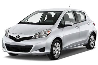
Cigar lighter (power outlet) fuse in the Toyota Yaris Hybrid / Echo Hybrid is the fuse #15 “CIG” in the Instrument panel fuse box.
Table of Contents
Passenger Compartment Fuse Box
Passenger Compartment Fuse Box
Fuse box location
The fuse box is located under the instrument panel (left-side), behind the cover.
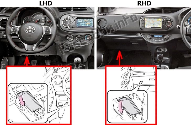
Fuse box diagram
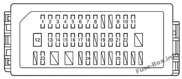
Assignment of the fuses in the Passenger Compartment
| № | Name | Ampere | Circuit |
|---|---|---|---|
| 1 | TAIL NO.2 | 10 | Front position lights, tail lights, license plate lights |
| 2 | PANEL | 5 | Instrument panel lights, manual headlight leveling dial, gauge and meters |
| 3 | DOOR R/R | 20 | Power windows |
| 4 | DOOR P | 20 | Power windows |
| 5 | ECU-IG NO.1 | 5 | Rear window defogger, main body ECU, brake system, vehicle stability control system, shift lock control system, audio system, windshield wipers |
| 6 | ECU-IG NO.2 | 5 | Electric power steering system |
| 7 | A/C | 7,5 | Air conditioning system |
| 8 | GAUGE | 10 | Back-up lights, shift lock control system, rear seat belt reminder lights, auto anti-glare inside rear view mirror, hybrid transmission, audio system, multiport fuel injection system/sequential multiport fuel injection system, rain sensor |
| 9 | WASHER | 15 | Windshield wipers and washer |
| 10 | WIPER | 20 | Windshield wipers and washer |
| 11 | WIPER RR | 15 | Rear window wiper |
| 12 | P/W | 30 | Power windows |
| 13 | DOOR R/L | 20 | Power windows |
| 14 | DOOR | 20 | Power windows |
| 15 | CIG | 15 | Power outlets |
| 16 | ACC | 5 | Main body ECU, outside rear view mirrors, audio system, Stop & Start system, shift lock control system |
| 17 | D/L | 25 | Power door lock system |
| 18 | OBD | 7,5 | On-board diagnosis system |
| 19 | FOG RR | 7,5 | Rear fog light, gauge and meters |
| 20 | STOP | 7,5 | Starter system, shift lock control system, brake system, stop lights, high mounted stoplight |
| 21 | AM1 | 7,5 | No circuit |
| 22 | FOG FR | 7,5 | Front fog lights, gauge and meters |
| 23 | D-D/L | 25 | D-D/L |
| 24 | SHADE | 25 | — |
| 25 | S-HTR | 15 | Seat heaters |
Engine Compartment Fuse Box №1
Engine Compartment Fuse Box №1
Fuse box location
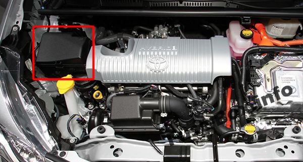
Fuse box diagram
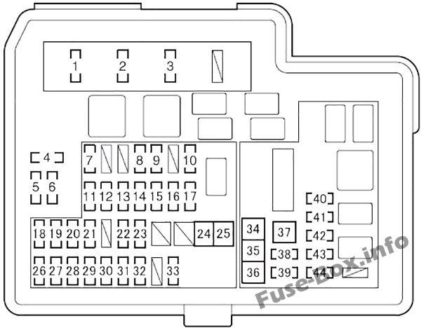
Assignment of the fuses in the Engine Compartment Fuse Box №1
| № | Name | Ampere | Circuit |
|---|---|---|---|
| 1 | EFI MAIN | 20 | Multiport fuel injection system/sequential multiport fuel injection system, EFI NO.2 |
| 2 | HORN | 10 | Horn |
| 3 | IG2 | 10 | IG2 NO.2, METER, IGN |
| 4 | SPARE | 5 | Spare fuse |
| 5 | SPARE | 7,5 | Spare fuse |
| 6 | SPARE | 30 | Spare fuse |
| 7 | EFI NO.2 | 10 | Multiport fuel injection system/sequential multiport fuel injection system |
| 8 | H-LP RH-LO | 10 | Right-hand headlight (low beam) |
| 9 | H-LP LH-LO | 10 | Left-hand headlight (low beam), manual headlight leveling dial |
| 10 | FOG FR NO.2 | 7,5 | Front fog lights |
| 11 | IG2 NO.2 | 10 | Smart entry & start system, pushbutton start system, multiport fuel injection system/sequential multiport fuel injection system, SRS airbag system, steering lock system, stop lights |
| 12 | DOME | 15 | Audio system, main body ECU, personal lights, foot well lights |
| 13 | ECU-B NO.1 | 5 | Main body ECU, smart entry & start system |
| 14 | METER | 7,5 | Gauge and meters |
| 15 | IGN | 15 | Multiport fuel injection system/sequential multiport fuel injection system |
| 16 | H-LP RH-HI | 5 | Right-hand headlight (high beam) |
| 17 | H-LP LH-HI | 5 | Left-hand headlight (high beam), gauge and meters |
| 18 | D/L NO.2 | 25 | Power door lock |
| 19 | HAZ | 10 | Emergency flashers |
| 20 | ETCS | 10 | Multiport fuel injection system/sequential multiport fuel injection system |
| 21 | ABS NO.1 | 20 | Brake system |
| 22 | ENG W/PMP | 30 | Multiport fuel injection system/sequential multiport fuel injection system |
| 23 | H-LP- MAIN | 20 | H-LP LH-LO, H-LP RH-LO, H-LP LH-HI, H-LP RH-HI |
| 24 | ABS MTR NO.1 | 30 | Brake system |
| 25 | P/I | 50 | EFI-MAIN, HORN, IG2 |
| 26 | ECU-B NO.2 | 5 | Air conditioning system, gauge and meters, smart entry & start system, pushbutton start system |
| 27 | AM2 | 7,5 | Start system |
| 28 | DRL | 7,5 | Daytime running lights |
| 29 | STRG LOCK | 20 | Starter system |
| 30 | ABS NO.2 | 7,5 | Brake system |
| 31 | AMP | 15 | Audio system |
| 32 | IGCT- MAIN | 30 | IGCT NO.2, IGCT NO.3, IGCT NO.4, PCU, BATT FAN |
| 33 | D/C CUT | 30 | DOME, ECU-B NO.1 |
| 34 | PTC HTR NO.1 | 30 | No circuit |
| 35 | PTC HTR NO.2 | 30 | No circuit |
| 36 | FAN | 30 | Electric cooling fan |
| 37 | PTC HTR NO.3 | 30 | No circuit |
| 38 | DEF | 25 | MIR HTR, rear window defogger |
| 39 | MIR HTR | 10 | Outside rear view minor defogger |
| 40 | BATT FAN | 10 | Battery cooling fan |
| 41 | IGCT NO.2 | 10 | Hybrid system |
| 42 | IGCT NO.4 | 10 | Hybrid system |
| 43 | PCU | 10 | Hybrid system |
| 44 | IGCT NO.3 | 10 | Hybrid system |
Engine Compartment Fuse Box №2
Engine Compartment Fuse Box №2
Fuse box location
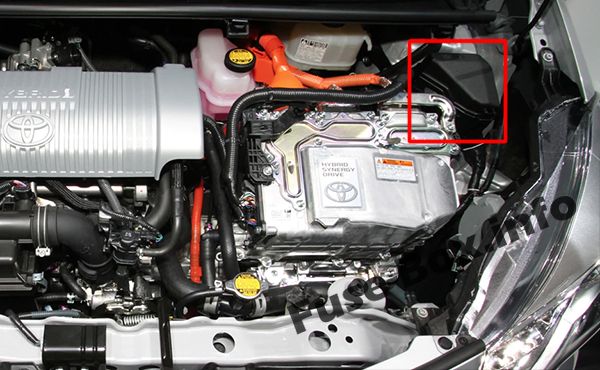
Fuse box diagram
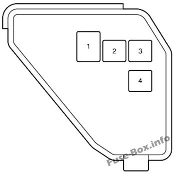
Assignment of the fuses in the Engine Compartment Fuse Box №2
| № | Name | Ampere | Circuit |
|---|---|---|---|
| 1 | DC/DC | 100 | Hybrid system |
| 2 | ABS MTR NO.2 | 30 | Brake system |
| 3 | HTR | 40 | Air conditioning system |
| 4 | EPS | 50 | Electric power steering system |


