


Fuse Layout Toyota RAV4 2006-2012
Contents

Cigar lighter (power outlet) fuses in the Toyota RAV4 are the fuses #23 “CIG” (Cigarette lighter), #24 “ACC” (Power outlets), #27 “PWR OUTLET” (Power outlets), #12 “ACC-B” in the Instrument panel fuse box, and fuse #18 “AC INV” (Power Outlet 115V) in the Engine Compartment Fuse Box №1.
Table of Contents
Passenger Compartment Overview
Passenger Compartment Overview
Left-hand drive vehicles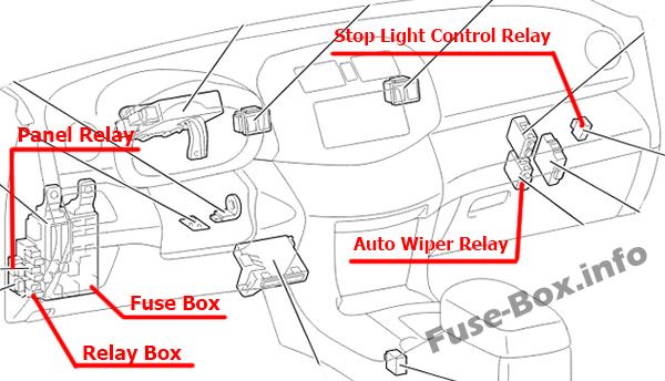
Right-hand drive vehicles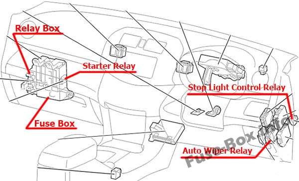
Passenger Compartment Fuse Box
Fuse box location
The fuse box is located under the instrument panel (on the left side), behind the cover.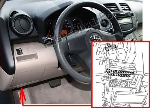
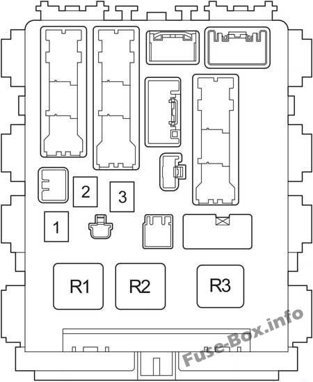
Fuse box diagram
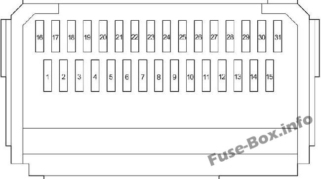
Assignment of the fuses in the Passenger Compartment
| № | Name | Amp | Circuit |
|---|---|---|---|
| 1 | – | – | Not used |
| 2 | S-HTR | 15 | Seat heaters |
| 3 | WIP | 25 | Windshield wipers |
| 4 | RR WIP | 15 | Rear window wiper |
| 5 | WSH | 15 | Windshield washer, rear window washer |
| 6 | ECU-IG1 | 10 | Electric cooling fans, anti-lock brake system, traction control system, vehicle stability control system, downhill assist control system, hill-start assist control system, Active Torque Control 4WD system, automatic transmission shift lock system, air conditioning system, main body ECU, electric moon roof, windshield wiper de-icer, stop/tail lights, electric power steering system, clock, auto anti-glare inside rear view mirror |
| 7 | ECU-IG2 | 10 | Air conditioning system, rear window defogger |
| 8 | OBD | 7.5 | On-board diagnosis system |
| 9 | STOP | 10 | Stop/tail lights, high mounted stoplight, automatic transmission shift lock system, multiport fuel injection system/sequential multiport fuel injection system, anti-lock brake system, traction control system, vehicle stability control system, downhill assist control system, hill-start assist control system |
| 10 | – | – | Not used |
| 11 | DOOR | 25 | Main body ECU, power door lock system |
| 12 | ACC-B | 25 | “ACC”, “CIG” fuses |
| 13 | 4WD | 7.5 | Active Torque Control 4WD system |
| 14 | FR FOG | 15 | Front fog lights |
| 15 | AM1 | 7.5 | Starting system |
| 16 | TAIL | 10 | Tail lights, parking lights, license plate light, front fog lights, rear fog lights |
| 17 | PANEL | 7.5 | Clock, instrument panel lights, audio system |
| 18 | GAUGE1 | 10 | Buck-up lights, charging system |
| 19 | D FR DOOR | 20 | Power windows (front doors) |
| 20 | RL DOOR | 20 | Power windows |
| 21 | RR DOOR | 20 | Power windows |
| 22 | S/ROOF | 25 | Electric moon roof |
| 23 | CIG | 15 | Cigarette lighter |
| 24 | ACC | 7.5 | Audio system, power outlets, power rear view mirror control, automatic transmission shift lock system, main body ECU, clock |
| 25 | – | – | Not used |
| 26 | MIR HTR | 10 | Outside rear view heaters |
| 27 | PWR OUTLET | 15 | Power outlets |
| 28 | – | – | Not used |
| 29 | RR FOG | 10 | Rear fog light |
| 30 | IGN | 7.5 | SRS airbag system, multiport fuel injection system/sequential multiport fuel injection system, stop/tail lights, starting system |
| 31 | GAUGE2 | 7.5 | Meters and gauges |
| № | Name | Amp | Circuit |
|---|---|---|---|
| 1 | POWER | 30 | Power windows |
| 2 | DEF | 30 | Rear window defogger, “MIR HTR” fuse |
| 3 | P/SEAT | 30 | Power seat |
| Relay | |||
| R1 | Ignition (IG1) | ||
| R2 | Heater (Manual A/C) Short Pin (Automatic A/C) | ||
| R3 | LHD: Turn Signal Flasher |
Relay Box
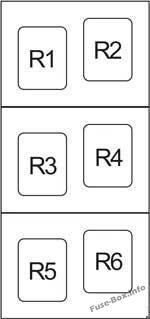
| № | Relay |
|---|---|
| R1 | Starter (ST CUT) |
| R2 | LHD: Starter (ST) (Gasoline, Before Dec. 2008: Diesel with Entry & Start System) LHD: Short Pin (Before Dec. 2008: Diesel without Entry & Start System) |
| R3 | Front fog light (FR FOG) |
| R4 | Rear fog light (RR FOG) Power Outlet (115V) |
| R5 | Accessory (ACC) |
| R6 | Power outlet (PWR OUTLET) |
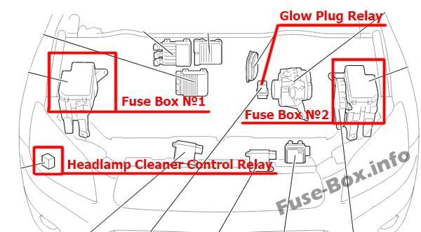
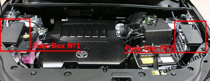
Engine Compartment Fuse Boxes
Engine Compartment Fuse Boxes
Fuse box location
Fuse Box №1 Diagram
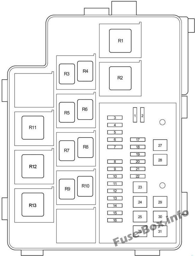
Assignment of the fuses and relay in the Engine Compartment Fuse Box №1
| № | Name | Amp | Circuit |
|---|---|---|---|
| 1 | – | – | Not used |
| 2 | – | – | Not used |
| 3 | – | – | Not used |
| 4 | ECU-B2 | 7.5 | Air conditioning system, power windows |
| 5 | ALT-S | 7.5 | Charging system |
| 5 | RSE | 7.5 | Audio System (JBL) |
| 6 | STR LOCK | 20 | No circuit |
| 7 | – | – | Not used |
| 8 | DCC | – | – |
| 9 | RAD No.1 | 20 | Audio system |
| 10 | ECU-B | 10 | Wireless remote control system, main body ECU, clock, meters, gauges and vehicle stability control system, electric power steering system |
| 11 | DOME | 10 | Ignition switch light, interior light, vanity lights, luggage compartment light, front personal lights, foot lights |
| 12 | – | – | – |
| 13 | HEAD LH | 10 | Left-hand headlight (high beam) |
| 14 | HEAD RH | 10 | Right-hand headlight (high beam) |
| 15 | HEAD LL | 10 | Left-hand headlight (low beam) |
| 16 | HEAD RL | 10 | Right-hand headlight (low beam) |
| 17 | – | – | – |
| 18 | AC INV | 15 | Power Outlet (115V) |
| 19 | TOWING | 30 | Trailer Towing |
| 20 | STV HTR | 25 | No circuit |
| 21 | – | – | Not used |
| 22 | DEICER | 20 | Front Window Deicer |
| 23 | HTR | 50 | Air conditioning system |
| 24 | PTC3 | 50 | PTC heater |
| 25 | PTC2 | 50 | PTC heater |
| 26 | PTC1 | 50 | PTC heater |
| 27 | HEAD MAIN | 50 | “HEAD LL”, “HEAD RL”, “HEAD LH”, “HEAD RH” fuses |
| 28 | – | – | Not used |
| 29 | RDI | 30 | without towing package (except 2GR-FE): Electric cooling fans |
| 29 | FAN2 | 50 | with towing package (2GR-FE): Electric cooling fans |
| 30 | CDS | 30 | without towing package (except 2GR-FE): Electric cooling fans |
| 30 | FAN1 | 50 | with towing package (2GR-FE): Electric cooling fans |
| 31 | H-LP CLN | 30 | No circuit |
| Relay | |||
| R1 | Dimmer | ||
| R2 | Headlight | ||
| R3 | Daytime running light relay (No.4) | ||
| R4 | Daytime running light relay (No.3) | ||
| R5 | Except 2GR-FE: Electric cooling fan (No.3) | ||
| R6 | Except 2GR-FE: Electric cooling fan (No.2) | ||
| R7 | Except 2GR-FE: Electric cooling fan (No.1) | ||
| R8 | Not used | ||
| R9 | Front Window Deicer | ||
| R10 | Daytime running light relay (No.2) | ||
| R11 | Except 2GR-FE: PTC heater (PTC NO.3) | ||
| R12 | Except 2GR-FE: PTC heater (PTC NO.2) 2GR-FE: Electric cooling fan (No.2) |
||
| R13 | 2GR-FE: Electric cooling fan (No.1) Except 2GR-FE: PTC heater (PTC No.1) |
Fuse Box №2 Diagram
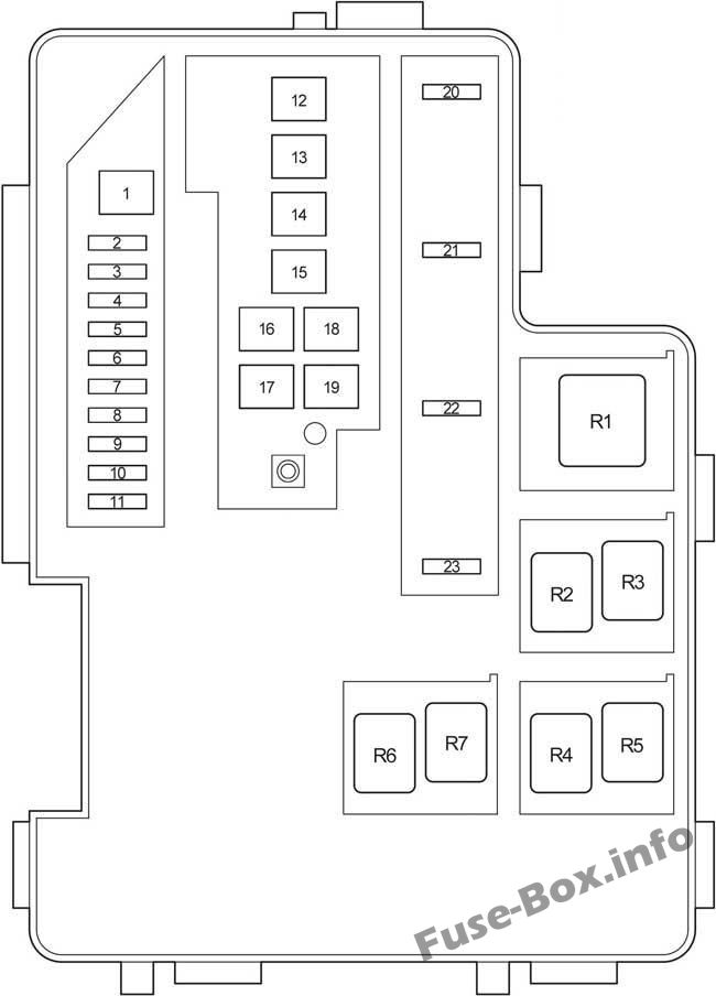
Assignment of the fuses and relay in the Engine Compartment Fuse Box №2
| № | Name | Amp | Circuit |
|---|---|---|---|
| 1 | P-SYSTEM | 30 | 3ZR-FAE: Valve lift control driver |
| 2 | AMP | 30 | Audio System (JBL) |
| 3 | AM2 | 30 | Starting system |
| 4 | IG2 | 15 | Engine control, ignition |
| 5 | HAZ | 10 | Emergency flashers |
| 6 | ETCS | 10 | Cruise Control, Electronically Controlled Transmission and A/T Indicator, Engine Control, Engine Immobiliser System |
| 7 | AM2-2 | 7.5 | Starting system |
| 8 | – | – | – |
| 9 | EFI NO.1 | 10 | Multiport fuel injection system/sequential multiport fuel injection system |
| 10 | EFI NO.2 | 10 | Multiport fuel injection system/sequential multiport fuel injection system |
| 11 | EFI NO.3 | 7.5 | A/T; From Dec. 2008: Multiport fuel injection system/sequential multiport fuel injection system |
| 11 | STA | 7.5 | Starting system, multiport fuel injection system/sequential multiport fuel injection system |
| 12 | GLOW | 80 | Engine glow system |
| 13 | EM PS | 60 | Electric power steering system |
| 14 | MAIN | 80 | “HEAD MAIN”, “ECU-B2”, “DOME”, “ECU-B”, “RAD NO.1” fuses |
| 15 | ALT | 120 | Gasoline, (without towing package): “ABS 1”, “ABS 2”, “RDI”, “CDS”, “HTR”, “TOWING” fuses |
| 15 | ALT | 140 | Diesel, (with towing package): “ABS 1”, “ABS 2”, “RDI”, “CDS”, “HTR”, “TOWING” fuses |
| 16 | P/I | 50 | “EFI MAIN”, “HORN”, “A/F”, “EDU” fuses |
| 17 | – | – | Not used |
| 18 | ABS 2 | 30 | Anti-lock brake system, traction control system, vehicle stability control system, downhill assist control system, hill-start assist control system |
| 19 | ABS 1 | 50 | Anti-lock brake system, traction control system, vehicle stability control system, downhill assist control system, hill-start assist control system |
| 20 | EFI MAIN | 20 | Multiport fuel injection system/sequential multiport fuel injection system, “EFI NO.1”, “EFI NO.2”, “EFI NO.3” fuses |
| 21 | HORN | 10 | Horn |
| 22 | EDU | 25 | Multiport fuel injection system/sequential multiport fuel injection system |
| 23 | A/F | 20 | Gasoline: A/F sensor Diesel: Multiport fuel injection system/sequential multiport fuel injection system |
| 23 | IGT/INJ | 15 | 3ZR-FAE: Multiport fuel injection system/sequential multiport fuel injection system |
| Relay | |||
| R1 | VSC MTR Relay | ||
| R2 | Not used | ||
| R3 | VSC FAIL Relay | ||
| R4 | Ignition (IG2) | ||
| R5 | BRK Relay | ||
| R6 | Air conditioning (MG CLT) | ||
| R7 | Fuel pump |


