


Fuse Layout Toyota RAV4 2001-2005
Contents

Cigar lighter (power outlet) fuses in the Toyota RAV4 are the fuse #2 “CIG” (Cigarette lighter) and #3 “POWER OUTLET (Power outlets) in the Instrument panel fuse box.
Table of Contents
Passenger Compartment Overview
Passenger Compartment Overview
Left-hand drive vehicles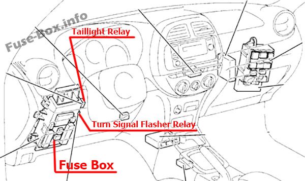
Right-hand drive vehicles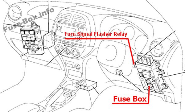
Passenger Compartment Fuse Box
Fuse box location
The fuse box is located in the instrument panel (on the driver’s side), behind the cover.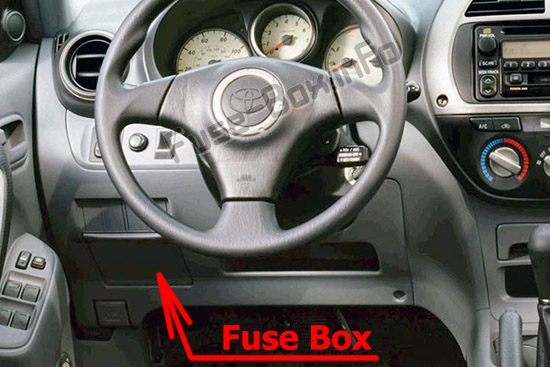
Fuse box diagram
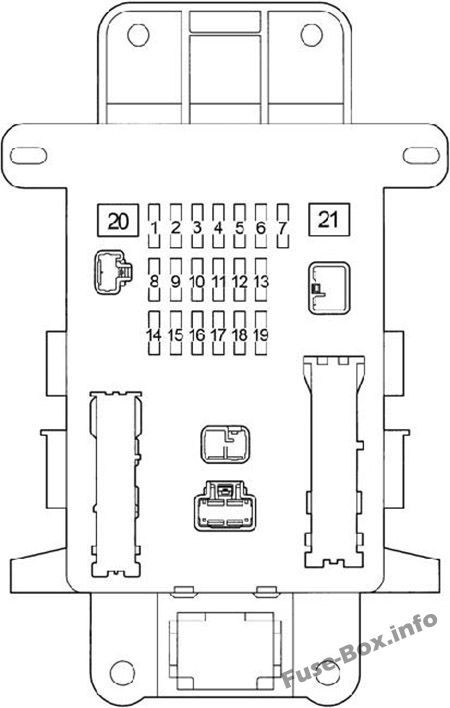
Assignment of the fuses in the Passenger Compartment Fuse Box
| № | Name | Amp | Circuit |
|---|---|---|---|
| 1 | STOP | 10 | Stop lights, high-mounted stoplight, anti-lock brake system, shift lock control system, multiport fuel injection system/sequential multiport fuel injection system, cruise control system |
| 2 | CIG | 15 | Cigarette lighter |
| 3 | POWER OUTLET | 15 | Power outlets |
| 4 | S-HTR | 10 | Seat heater |
| 5 | PANEL | 7.5 | Instrument panel light, gauges and meters, front fog lights, instrument panel light control, outside rear view mirror defoggers, air conditioning system |
| 6 | FR FOG | 15 | Front fog lights |
| 7 | HORN | 10 | Horn |
| 8 | TAIL | 7.5 | Tail lights, license plate lights, instrument cluster lights |
| 9 | TAIL&PANEL | 15 | “PANEL” and “TAIL” fuses |
| 10 | ACC | 7.5 | Car audio system, shift lock control system, clock, power rear view mirrors |
| 11 | DEF | 20 | Rear window defogger |
| 12 | GAUGE | 10 | Back-up lights, electric cooling fans, air conditioning system, automatic transmission indicator lights, charging system |
| 13 | OBD | 7.5 | On-board diagnosis system |
| 14 | IG2 | 10 | Discharge warning light, multiport fuel injection system/sequential multiport fuel injection system, starting system, SRS airbag system, gauges and meters |
| 15 | DOOR | 20 | Power door lock system |
| 16 | MIR HTR | 10 | Outside rear view mirror defoggers |
| 17 | RR WIP | 15 | Rear window wiper and washer |
| 18 | WIP | 25 | Windshield wipers and washer |
| 19 | ECU IG | 10 | Emergency flashers, gauges and meters, anti-lock brake system, SRS airbag system, shift lock control system, cruise control system, vehicle stability control system, traction control system |
| 20 | POWER | 30 | Electric moon roof, power windows |
| 21 | AM1 | 40 | Power outlets, rear window defogger, “ACC”, “CIG”, “ECU IG”, “GAUGE”, “RR WIP”, “S-HTR” and “WIP” fuses |
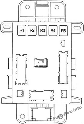
| № | Relay |
|---|---|
| R1 | Horn |
| R2 | Rear fog light (RR FOG) |
| R3 | Rear window defogger (DEF) |
| R4 | Power outlet (PWR OUTLET) |
| R5 | Power window (PWR) |
Engine Compartment Fuse Box
Engine Compartment Fuse Box
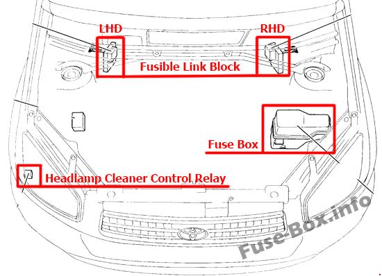
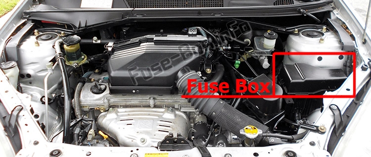
Fuse box location
Fuse box diagram
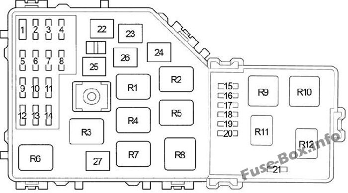
Assignment of the fuses and relay in the Engine Compartment
| № | Name | Amp | Circuit |
|---|---|---|---|
| 1 | – | – | Short pin |
| 2 | ALT-S | 5 | Charging system |
| 3 | A/F | 20 | A/F sensor |
| 3 | RADIO NO.2 | 30 | Audio system |
| 4 | EFI1 | 20 | Multiport fuel injection system/sequential multiport fuel injection system, automatic transmission fluid temperature sensor, “EFI2” and “EFI3” fuses |
| 5 | CUT | 30 | “RADIO” and “DOME” fuses |
| 6 | HAZ | 10 | Emergency flashers |
| 7 | EFI2 | 5 | Multiport fuel injection system/sequential multiport fuel injection system |
| 8 | ABS 2 | 30 | Anti-lock brake system, vehicle stability control system, traction control system, brake assist system |
| 9 | DOME | 10 | Clock, personal light, interior lights, air conditioning system, wireless remote control system, headlight high beam indicator light, gauges and meters, headlight high beam indicator light |
| 10 | MAIN | 30 | “H-LP RH” and “H-LP LH” fuses |
| 11 | EFI3 | 10 | Multiport fuel injection system/sequential multiport fuel injection system, emission control system |
| 12 | RADIO | 15 | Car audio system |
| 13 | A/C | 5 | Air conditioning system |
| 14 | IGN | 15 | Starting system, multiport fuel injection system/sequential multiport fuel injection system |
| 15 | – | – | – |
| 16 | – | – | – |
| 17 | ETCS | 10 | Electronic throttle control system |
| 18 | H-LP RH | 10 | Right-hand headlight |
| 19 | H-LP LH | 10 | Left-hand headlight |
| 20 | INJ | – | Multiport fuel injection system/sequential multiport fuel injection system |
| 21 | ST | 5 | Starting system |
| 22 | AM2 | 30 | Discharge warning light, multiport fuel injection system/sequential multiport fuel injection system, starting system, SRS airbag system and “IG2” fuse |
| 23 | HTR | 40 | Air conditioning system |
| 24 | H-LP CLN | 30 | Headlight cleaner |
| 24 | F-HTR | 30 | Fuel heater |
| 25 | CDS | 30 | Electric cooling fan |
| 26 | ABS 1 | 40/50 | Anti-lock brake system |
| 27 | RDI | 30 | Electric cooling fan |
| Relay | |||
| R1 | Engine control unit (EFI MAIN) | ||
| R2 | Electric cooling fan (FAN NO.3) | ||
| R3 | Ignition (IG2) | ||
| R4 | Electric cooling fan (FAN NO.2) | ||
| R5 | Air fuel ratio sensor (A/F) | ||
| R6 | Electric cooling fan (FAN NO.2) | ||
| R7 | Fuel pump (C/OPN) | ||
| R8 | Heater (HTR) | ||
| R9 | Starter (ST) | ||
| R10 | Daytime running light (DRL) | ||
| R11 | Engine control unit | ||
| R12 | – |


