


Fuse Layout Toyota Prius V / Prius+ / Prius Alpha 2012-2018
Contents

Cigar lighter (power outlet) fuses in the Toyota Prius V / Prius+ / Prius α are the fuses #1 “CIG” and #3 “PWR OUTLET” in the Instrument panel fuse box.
Table of Contents
Passenger compartment overview
Passenger compartment overview
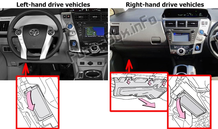
Left-hand drive vehicles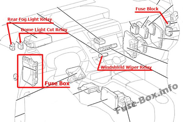
Right-hand drive vehicles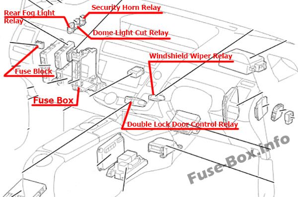
Passenger Compartment Fuse Box
Fuse box location
The fuse box is located under the instrument panel (left side), under the lid.
Left-hand drive vehicles: open the lid.
Right-hand drive vehicles: remove the cover and open the lid.
Fuse box diagram
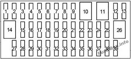
Assignment of the fuses in the Passenger Compartment
| № | Name | Amp | Circuit |
|---|---|---|---|
| 1 | CIG | 15 | Power outlets |
| 2 | ECU-ACC | 10 | Multiplex communication system, outside rear view mirrors, driver support system, audio system, navigation system |
| 3 | PWR OUTLET | 15 | Power outlets |
| 4 | – | – | – |
| 5 | SEAT HTR FR | 10 | Seat heater |
| 6 | – | – | – |
| 7 | SEAT HTR FL | 10 | Seat heater |
| 8 | DOOR NO.1 | 25 | Power door lock system |
| 9 | – | – | – |
| 10 | PSB | 30 | Pre-Collision System |
| 11 | PWR SEAT FR | 30 | Power seat |
| 12 | DBL LOCK | 25 | RHD: Double locking |
| 13 | FR FOG | 15 | Before Nov. 2014: Front fog lights |
| 13 | FR FOG | 7.5 | From Nov. 2014: Front fog lights |
| 14 | PWR SEAT FL | 30 | Power seat |
| 15 | OBD | 7.5 | On-board diagnosis system |
| 16 | – | – | – |
| 17 | RR FOG | 7.5 | Rear fog lights |
| 18 | – | – | – |
| 19 | STOP | 10 | Stop lights, high mounted stoplight, brake system, driver support system, vehicle proximity notification system |
| 20 | – | – | – |
| 21 | P FR DOOR | 25 | Power windows |
| 22 | D FR DOOR | 25 | Power windows |
| 23 | – | – | – |
| 24 | DOOR RR | 25 | Power windows |
| 25 | DOOR RL | 25 | Power windows |
| 26 | S/ROOF | 30 | Panoramic roof shades |
| 27 | ECU-IG NO.1 | 10 | Electric cooling fans, multiplex communication system |
| 28 | ECU-IG NO.2 | 10 | Driver support system, Pre-Collision System, inside rear view mirror, garage door opener, yaw rate & G sensor, brake system, electric power steering, navigation system, panoramic roof shades, tire pressure warning system, seat belt pretensioners, audio system, emergency flashers, turn signal lights, windshield wipers, headlight cleaner |
| 29 | – | – | – |
| 30 | GAUGE | 10 | Headlight leveling system, gauges and meters, emergency flashers |
| 31 | A/C | 10 | Air conditioning system |
| 32 | WASHER | 15 | Windshield washer |
| 33 | RR WIP | 20 | Rear window wiper and washer |
| 34 | WIP | 30 | Windshield wipers |
| 35 | – | – | – |
| 36 | MET | 7.5 | Gauges and meters |
| 37 | IGN | 10 | Brake system, driver support system, multiport fuel injection system/sequential multiport fuel injection system, SRS airbag system, occupant detection system (ECU and sensors), smart key system |
| 38 | PANEL | 10 | Air conditioning system, emergency flashers, seat heaters, transmission, P position switch, navigation system, advanced parking guidance system, headlight cleaner, seat belt reminder light, headlight leveling system, glove box light, clock, audio system |
| 39 | TAIL | 10 | Headlight leveling system, parking lights, tail lights, license plate lights, front fog lights, side marker lights |
Additional Fuse Box
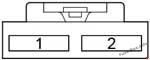
| № | Name | Amp | Circuit |
|---|---|---|---|
| 1 | WIP NO.4 | 10 | RHD: Cruise control, dynamic radar cruise control, engine control |
| 2 | WIP NO.4 | 10 | LHD: Cruise control, dynamic radar cruise control, engine control |
Fusible Link Block
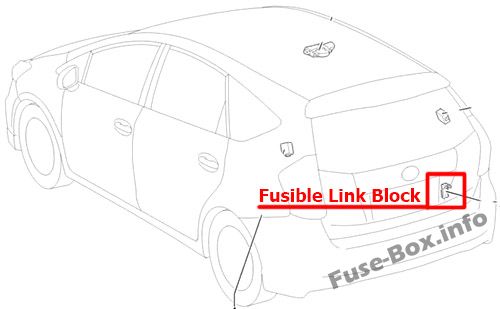
| № | Name | Amp | Circuit |
|---|---|---|---|
| 1 | MAIN | 140 | “DC/DC”, “DRL”, “AMP”, “AMP NO.1”, “AMP NO.2”, “H-LP HI MAIN”, “EPS”, “ABS MTR 1”, “ABS MTR 2”, “DC/DC-S”, “P/I 2”, “ECU-B2”, “AM2”, “ECU-B3”, “TURN & HAZ”, “P CON MAIN”, “SHORT PIN”, “ABS MAIN NO.1”, “P-CON MTR”, “MAYDAY”, “ETCS”, “IGCT”, “P/I 1” fuses |
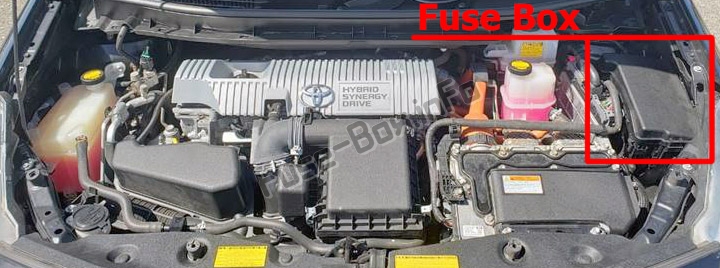
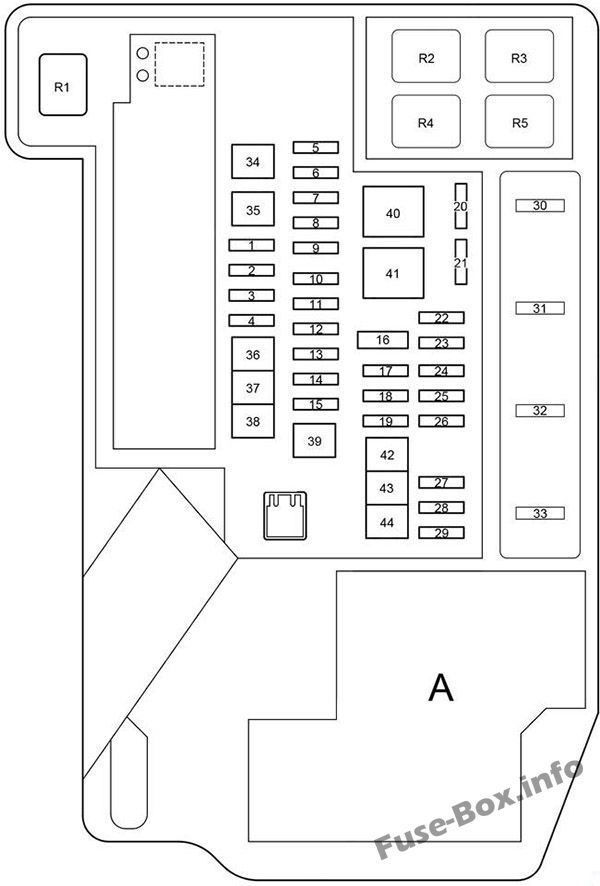
Engine Compartment Fuse Box
Engine Compartment Fuse Box
Fuse box location
Fuse box diagram
A:
Until Oct. 2012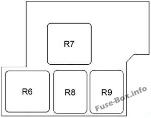
Since Oct. 2012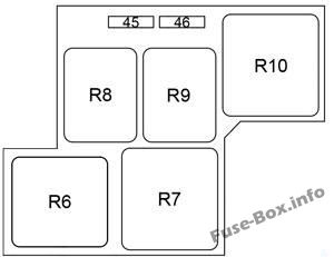
Assignment of the fuses and relay in the Engine Compartment
| № | Name | Amp | Circuit |
|---|---|---|---|
| 1 | ABS MAIN NO.2 | 7.5 | Anti-lock brake system |
| 2 | ENG W/P | 30 | Cooling system |
| 3 | S-HORN | 10 | Theft deterrent |
| 4 | AMP | 30 | From Nov. 2014: Audio system |
| 5 | ABS MAIN NO.1 | 20 | Anti-lock brake system |
| 6 | ETCS | 10 | Multiport fuel injection system/sequential multiport fuel injection system |
| 7 | TURN & HAZ | 10 | Turn signal lights |
| 8 | ECU-B3 | 10 | Air conditioning system |
| 9 | – | – | – |
| 10 | ECU-B2 | 7.5 | Smart key system |
| 11 | AM2 | 7.5 | Power management system |
| 12 | P CON MAIN | 7.5 | P position control system, transmission |
| 13 | DC/DC-S | 5 | Inverter and converter |
| 14 | IGCT | 30 | “PCU”, “IGCT NO.2”, “IGCT NO.3” fuses |
| 15 | AMP | 30 | Before Nov. 2014: Audio system |
| 15 | HORN | 10 | From Nov. 2014: Horn |
| 16 | SHORT PIN | – | “ECU-B”, “RAD NO.1”, “DOME” fuses |
| 17 | DRL | 7.5 | Daytime running lights |
| 18 | HV BATT | 10 | Battery voltage sensor |
| 19 | H-LP HI MAIN | 20 | Headlight switch, daytime running light system, “H-LP HI RH”, “H-LP HI LH” fuses |
| 20 | IGCT NO.3 | 10 | Cooling system |
| 21 | EFI NO.2 | 10 | Multiport fuel injection system/sequential multiport fuel injection system |
| 22 | H-LP RH HI | 10 | Right-hand headlight (high beam) |
| 23 | H-LP LH HI | 10 | Left-hand headlight (high beam) |
| 24 | ECU-B | 7.5 | Smart key system, multiplex communication system, personal lights, gauges and meters, occupant detection system (ECU and sensors) |
| 25 | DOME | 10 | Door courtesy lights, personal lights, interior lights, front foot lights, vanity lights, inside rear view mirror, garage door opener, overhead console |
| 26 | RAD NO.1 | 15 | Audio system, navigation system |
| 27 | MIR HTR | 10 | Outside rear view mirror defoggers |
| 28 | IGCT NO.2 | 10 | Hybrid system, P position control system, inverter and converter |
| 29 | PCU | 10 | Inverter and converter |
| 30 | IG2 | 20 | Multiport fuel injection system/sequential multiport fuel injection system, “MET 1 , “IGN” fuses, hybrid system |
| 31 | BATT FAN | 10 | Battery cooling fan |
| 32 | EFI MAIN | 20 | Multiport fuel injection system/sequential multiport fuel injection system, cooling system, “EFI NO.2” fuse |
| 33 | – | – | – |
| 34 | H-LP CLN | 30 | Headlight cleaner |
| 35 | – | – | – |
| 36 | CDS | 30 | Electric cooling fans |
| 37 | RDI | 30 | Electric cooling fans |
| 38 | HTR | 50 | Air conditioning system |
| 39 | P-CON MTR | 30 | P position control system, transmission |
| 40 | EPS | 60 | Electric power steering |
| 41 | P/I 1 | 60 | “IG2”, “EFI MAIN”, “BATT FAN” fuses |
| 42 | ABS MTR 2 | 30 | Anti-lock brake system |
| 43 | ABS MTR 2 | 30 | Anti-lock brake system |
| 44 | P/I 2 | 40 | Horn, right-hand headlight (low beam), left-hand head light (low beam), back-up lights |
| 45 | – | – | – |
| 46 | – | – | – |
| Relay | |||
| R1 | Cooling system (ENG W/P) | ||
| R2 | Electric cooling fan (FAN NO.3) | ||
| R3 | Shift control actuator (P-CON MTR) | ||
| R4 | Electric cooling fan (FAN NO.1) | ||
| R5 | Before Nov. 2014: Theft deterrent (S-HORN) From Nov. 2014: Daytime running lights (DRL) |
||
| R6 | Dimmer (DIM) | ||
| R7 | Power management control (IGCT) | ||
| R8 | Electric cooling fan (FAN NO.2) | ||
| R9 | Before Nov. 2014: Daytime running lights (DRL) From Nov. 2014: Horn |
||
| R10 | From Oct. 2012: – |
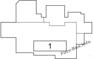
| № | Name | Amp | Circuit |
|---|---|---|---|
| 1 | DC/DC | 125 | Integration relay, “TAIL” relay, “P/POINT relay”, “ACC” relay, “IG1 NO.1” relay, “IG1 NO.2” relay, “IG1 NO.3” relay, “HTR”, “RDI”, “CDS”, “S-HORN”, “ENG W/P”, “ABS MAIN NO.2”, “H-LP CLN”, “FR FOG”, “PWR SEAT FL”, “OBD”, “STOP”, “RR FOG”, “DBL LOCK”, “PWR SEAT FR”, “DOOR NO.1”, “PSB”, “D FR DOOR”, “P FR DOOR”, “DOOR RL”, “DOOR RR”, “S/ROOF” fuses |


