

See other Toyota Camry:

Fuse Layout Toyota Camry 2007-2011
Contents

Cigar lighter (power outlet) fuses in the Toyota Camry are the fuses #29 “CIG” and #30 “PWR OUTLET” in the Instrument panel fuse box.
Table of Contents
Passenger Compartment Fuse Box
Passenger Compartment Fuse Box
Fuse box location
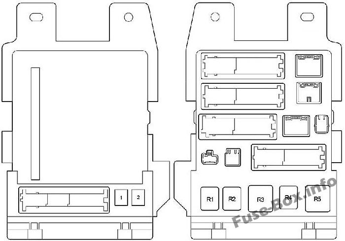
The fuse box is located under the instrument panel (on the driver’s side), under the cover.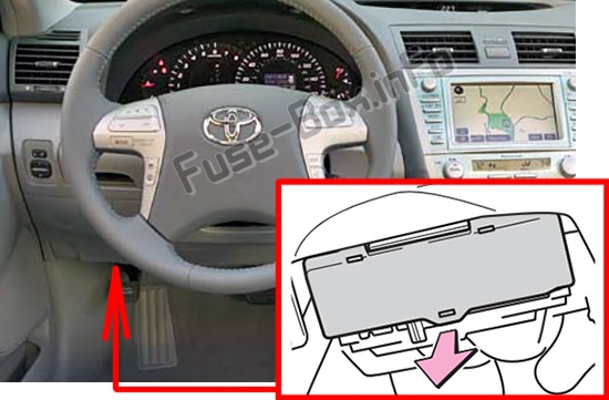
Fuse box diagram
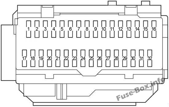
Assignment of the fuses in the Passenger Compartment
| № | Name | Amp | Circuit |
|---|---|---|---|
| 1 | RR DOOR RH | 25 | Rear right power window |
| 2 | RR DOOR LH | 25 | Rear left power window |
| 3 | FUEL OPN | 7.5 | No circuit |
| 4 | FR FOG | 15 | Front fog lights |
| 5 | OBD | 7.5 | On-board diagnosis system |
| 6 | ECU-B NO.2 | 7.5 | Power windows |
| 7 | STOP | 10 | Stop lights, high mounted stoplight, shift lock control system, multiport fuel injection system/sequential multiport fuel injection system, main body ECU, anti-lock brake system, vehicle stability control system, traction control system, brake assist system, electronic throttle control system |
| 8 | TI&TE | 30 | No circuit |
| 9 | – | – | Not used |
| 10 | AM1 | 7.5 | Multiport fuel injection system/sequential multiport fuel injection system |
| 11 | A/C | 7.5 | Air conditioning system |
| 12 | PWR | 25 | Power windows |
| 13 | DOOR NO.2 | 25 | Main body ECU |
| 14 | S/ROOF | 30 | Moon roof |
| 15 | TAIL | 15 | Front side marker/parking lights, stop/tail lights, rear side marker lights, license plate lights, back-up lights, front turn signal lights, main body ECU |
| 16 | PANEL | 7.5 | Navigation system, seat heaters, emergency flashers, air conditioning system, audio system, clock, glove box light, instrument panel lights, steering switches, vehicle stability control system, traction control system |
| 17 | ECU IG NO.1 | 10 | Main body ECU, windshield wipers and washer, moon roof, tire pressure warning system, electric cooling fans, auto anti-glare inside rear view mirror, navigation system |
| 18 | ECU IG NO.2 | 7.5 | Anti-lock brake system, vehicle stability control system, traction control system, brake assist system, shift lock control system, automatic transmission, cruise control system |
| 19 | A/C NO.2 | 10 | Air conditioning system, rear window defogger |
| 20 | WASH | 10 | Windshield wipers and washer |
| 21 | S-HTR | 20 | Seat heaters |
| 22 | GAUGE NO.1 | 10 | Emergency flashers, charging system, multiport fuel injection system/sequential multiport fuel injection system, back-up lights |
| 23 | WIP | 25 | Windshield wipers and washer |
| 24 | H-LP LVL | 7.5 | No circuit |
| 25 | INJ | 15 | Multiport fuel injection system/sequential multiport fuel injection system, starting system |
| 26 | IGN | 10 | Multiport fuel injection system/sequential multiport fuel injection system, theft deterrent system, SRS airbag system, steering lock system, front passenger occupant classification system, smart key system, electronic throttle control system |
| 27 | GAUGE NO.2 | 7.5 | Gages and meters, multi-information display, clock |
| 28 | ECU-ACC | 7.5 | Clock, main body ECU, shift lock control system, outside rear view mirror, smart key system |
| 29 | CIG | 20 | Power outlet |
| 30 | PWR OUTLET | 20 | Power outlet |
| 31 | RADIO NO.2 | 7.5 | Audio system, navigation system |
| 32 | MIR HTR | 10 | Outside rear view mirror defoggers |
| No. | Name | Amp | Circuit |
|---|---|---|---|
| 1 | P/SEAT | 30 | Power seats |
| 2 | POWER | 30 | Power windows |
| Relay | |||
| R1 | Fog Lights | ||
| R2 | Tail Lights | ||
| R3 | Accessory Relay | ||
| R4 | Power Window | ||
| R5 | IG1 Relay |
Fuse Box in the Engine Compartment
Fuse Box in the Engine Compartment
Fuse box location
It is located in the engine compartment (left-side).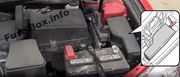
Fuse box diagram
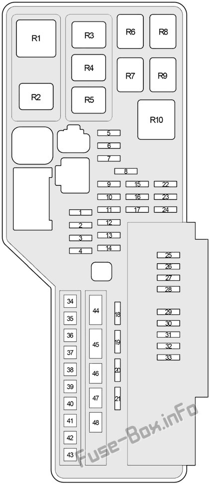
Assignment of the fuses in the Engine Compartment
| № | Name | Amp | Circuit |
|---|---|---|---|
| 1 | – | – | Not used |
| 2 | RR FOG | 10 | Rear fog light |
| 3 | FR DEF | 15 | |
| 4 | – | – | Not used |
| 5 | AM2 | 7.5 | Starting system |
| 6 | ALT-S | 7.5 | Charging system |
| 7 | MAYDAY/TEL | 7.5 | No circuit |
| 8 | – | – | Not used |
| 9 | EFI2 | 30 | 2AR-FE (2009-2011): Multiport fuel injection system/sequential multiport fuel injection system |
| 10 | E-ACM | 10 | 2GR-FE: No circuit |
| 11 | ETCS | 10 | Electronic throttle control system |
| 12 | HAZ | 15 | Turn signal lights, gauge and meters |
| 13 | IG2 | 20 | Multiport fuel injection system/sequential multiport fuel injection system, starting system, GAUGE NO.2, IGN, INJ |
| 14 | STR LOCK | 20 | Steering lock system |
| 15 | DOME | 10 | Gages and meters, vanity lights, trunk light, ignition switch light, door courtesy lights, interior light, personal lights, clock, smart key system |
| 16 | ECU-B NO.1 | 10 | Wireless remote control system, front passenger occupant classification system, main body ECU, vehicle stability control system |
| 17 | RADIO NO.1 | 15 | Audio system, navigation system |
| 18 | DOOR NO.1 | 25 | Main body ECU |
| 19 | – | – | – |
| 20 | AMP | 25 | Audio system |
| 21 | EFI MAIN | 30 | Multiport fuel injection system/sequential multiport fuel injection system, electronic throttle control system, main body ECU, “EFI NO.2” and “EFI NO.3” fuses |
| 22 | – | – | Not used |
| 23 | EFI NO.3 | 10 | Multiport fuel injection system/sequential multiport fuel injection system |
| 24 | EFI NO.2 | 15 | Multiport fuel injection system/sequential multiport fuel injection system |
| 25 | S-HORN | 7.5 | Horn |
| 26 | A/F | 20 | Multiport fuel injection system/sequential multiport fuel injection system |
| 27 | MPX-B | 10 | Gages and meters |
| 28 | EFI NO.1 | 10 | Theft deterrent system, smart key system, multiport fuel injection system/sequential multiport fuel injection system, electronic throttle control system |
| 29 | HORN | 10 | Horns |
| 30 | H-LP (RL) | 15 | Right-hand headlight (low beam) |
| 31 | H-LP (LL) | 15 | Left-hand headlight (low beam) |
| 32 | H-LP(RH) | 15 | Right-hand headlight (high beam) |
| 33 | H-LP (LH) | 15 | Left-hand headlight (high beam) |
| 34 | HTR | 50 | Air conditioning system |
| 35 | ABS NO.1 | 50 | Anti-lock brake system, vehicle stability control system, traction control system, brake assist system |
| 36 | FAN MAIN | 50 | 2GR-FE: Electric cooling fans |
| 37 | ABS NO.2 | 30 | Anti-lock brake system, vehicle stability control system, traction control system, brake assist system |
| 38 | RR DEF | 50 | Rear window defogger, “MIR HTR” fuse |
| 39 | RR PWR SEAT | 30 | No circuit |
| 40 | H-LP CLN | 30 | No circuit |
| 41 | CDS FAN | 40 | 2AR-FE: Electric cooling fans |
| 42 | RDI FAN | 40 | 2AR-FE: Electric cooling fans |
| 43 | MSB | 30 | No circuit |
| 44 | ALT | 120 | “RR FOG”, “FR DEF”, “AM2”, “ALT-S”, “MAYDAY/TEL”, “E-ACM”, “ETCS”, “HAZ”, “IG2”, “STR LOCK”, “DOME”, “ECU-B NO.1” “RADIO NO.1”, “EFI MAIN”, “AMP”, “DOOR NO.1”, “EFI NO.3”, “EFI NO.2”, “S-HORN”, “A/F”, “MPX-B”, “EFI NO.1”, “HORN”, “H-LP(RL)”, “H-LP(LL)” “H-LP(RH)”, “H-LP(LH)”, “HTR”, “ABS NO.1”, “FAN MAIN”, “ABS NO.2”, “RR DEF”, “RR PWR SEAT”, “H-LP CLN”, “CDS FAN”, “RDI FAN”, “MSB”, “ALT” and “ST/AM2” fuses |
| 45 | – | – | Not used |
| 46 | – | – | Not used |
| 47 | – | – | Not used |
| 48 | ST/AM2 | 30 | Starting system, GAUGE NO.2, IGN, INJ |
| Relay | |||
| R1 | VSC No.2 | ||
| R2 | VSC NO.1 | ||
| R3 | 2AZ-FE: Electric cooling fan (NO.1) | ||
| R4 | 2AZ-FE: Electric cooling fan (No.3) | ||
| R5 | 2AZ-FE: Electric cooling fan (No.2) 2GR-FE: Electric cooling fan |
||
| R6 | Starter | ||
| R7 | Ignition | ||
| R8 | MGC Relay | ||
| R9 | ST CUT Relay | ||
| R10 | Rear window defogger |


