

See other Toyota Aygo:

Fuse Layout Toyota Aygo 2014-2019…
Contents

Cigar lighter / power outlet fuse in the Toyota Aygo is the fuse #11 “P/OUTLET” in the Instrument panel fuse box.
Table of Contents
Passenger Compartment Fuse Box
Passenger Compartment Fuse Box
Fuse box location
Left-hand drive vehicles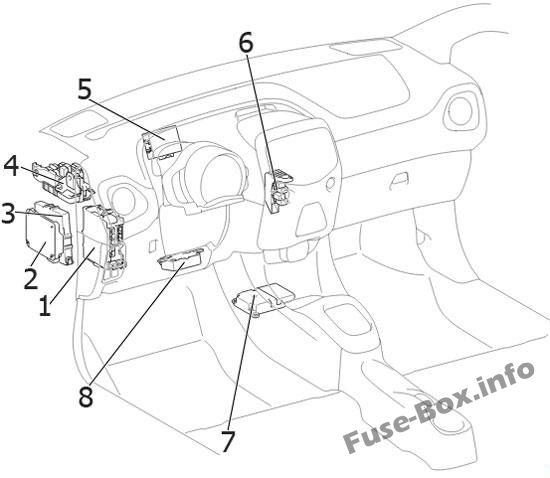
Right-hand drive vehicles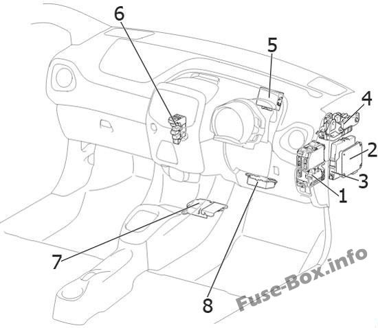
- Fuse Box / Main Body ECU
- Transmission Control Module
- Engine Stop and Start ECU
- Junction Connector
- Door Control ECU with Receiver (without Entry & Start System)
- Relay Box
- Airbag Sensor Assembly
- Power Steering ECU
The fuse box is located under the instrument panel (on the driver’s side).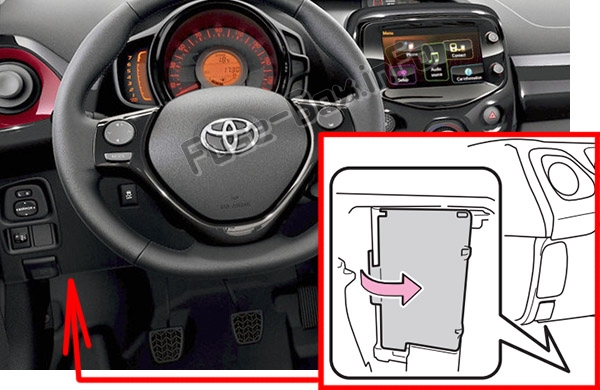
Fuse box diagram
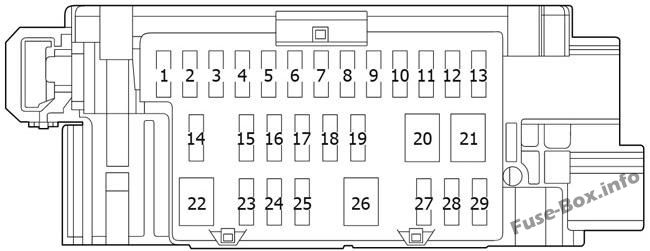
Assignment of the fuses in the Passenger Compartment
| № | Name | Amp | Circuit |
|---|---|---|---|
| 1 | IG1 NO.2 | 5 | Back-up light, multiport fuel injection system/sequential multiport fuel injection system, audio system, vehicle stability control system |
| 2 | WASHER | 15 | Windshield washer, rear window washer |
| 3 | ECU-IG NO.1 | 5 | Main body ECU, gauges and meters, air conditioning system, rear window defogger, outside rear view mirror defoggers, seat heaters, canvas top, audio system |
| 4 | ECU-IG NO.2 | 5 | Electric power steering system, Stop & Start system |
| 5 | WIPER RR | 15 | Rear window wiper |
| 6 | IG1 NO.1 | 5 | Electric cooling fan, anti-lock brake system, vehicle stability control system |
| 7 | WIPER | 25 | Windshield wiper |
| 8 | MIR HTR | 10 | Outside rear view mirror defoggers |
| 9 | P/OUTLET | 15 | Power outlet |
| 10 | ECU-ACC | 7.5 | Outside rear view mirrors, audio system, Stop 8t Start system, gauges and meters |
| 11 | IG2 NO.2 | 5 | Steering lock system, multiport fuel injection system/sequential multiport fuel injection system, multi-mode manual transmission |
| 12 | A/BAG | 7.5 | SRS airbag system |
| 13 | METER | 5 | Gauges and meters, Stop & Start system |
| 14 | IG2 NO.1 | 7.5 | 1PP (HM01): Multiport fuel injection system/sequential multiport fuel injection system, stop lights |
| 14 | IG2 NO.1 | 15 | 1KR-FE: Multiport fuel injection system/sequential multiport fuel injection system, stop lights |
| 15 | EFI NO.1 | 7.5 | 1KR-FE: Multiport fuel injection system/sequential multiport fuel injection system, Stop & Start system |
| 15 | EFI NO.1 | 10 | 1PP (HM01): Multiport fuel injection system/sequential multiport fuel injection system, Stop & Start system |
| 16 | OBD | 7.5 | On-board diagnosis system |
| 17 | STOP | 10 | Stop lights, high mounted stoplight, multiport fuel injection system/sequential multiport fuel injection system, anti-lock brake system, vehicle stability control system, multi-mode manual transmission, smart entry & start system |
| 18 | TAIL | 10 | Position lights, license plate lights, rear fog light, front fog lights, tail lights, switch illumination, multiport fuel injection system/sequential multiport fuel injection system, gauges and meters, audio system |
| 19 | – | – | – |
| 20 | HTR | 40 | Air conditioning system |
| 21 | AM1 | 40 | “HTR”, “OBD”, “A/C”, “TAIL”, “FOG RR”, “STOP”, “P/W”, “DOOR F/L”, “DOOR F/R” fuses |
| 22 | AM2 NO.1 | 30 | “EFI NO.2”, “EFI-MAIN”, “D/L” fuses |
| 23 | EFI NO.2 | 7.5 | 1KR-FE: Multiport fuel injection system/sequential multiport fuel injection system |
| 24 | EFI-MAIN | 20 | 1KR-FE: Multiport fuel injection system/sequential multiport fuel injection system, fuel pump, “EFI NO.1” fuses |
| 25 | D/L | 25 | Main body ECU, door lock system |
| 26 | P/W | 30 | Power windows |
| 27 | DOOR F/R | 25 | LHD: Power windows |
| 27 | DOOR F/L | 25 | RHD: Power windows |
| 28 | A/C | 10 | Air conditioning system |
| 29 | FOG RR | 5 | Rear fog light |
Relay Box
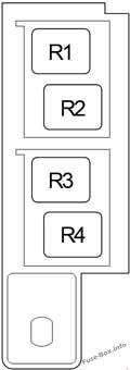
| № | Relay |
|---|---|
| R1 | Ignition (IG1) |
| R2 | without Entry & Start System: Starter (ST CUT) with Entry & Start System: Ignition (IG2) |
| R3 | Tail lights (TAIL) |
| R4 | Rear window defogger (RR DEF) |
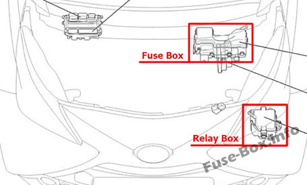
Engine Compartment Fuse Box
Engine Compartment Fuse Box
Fuse box location
Fuse box diagram
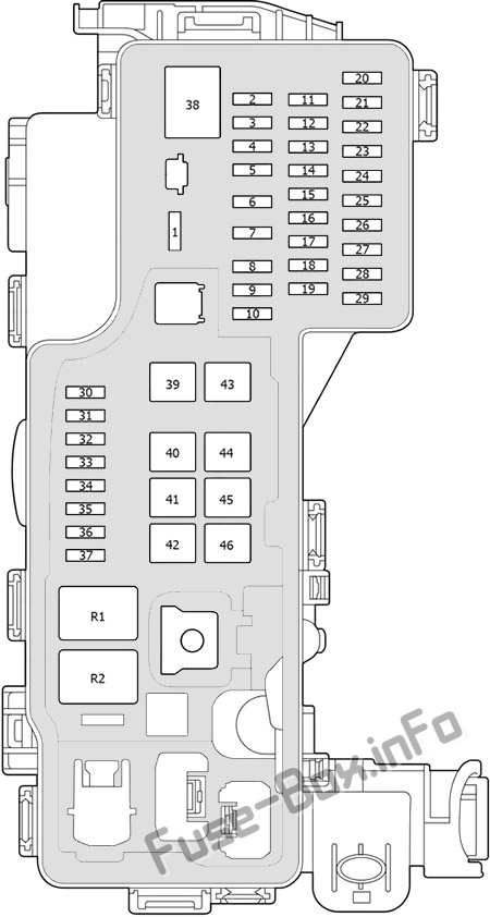
Assignment of the fuses in the Engine Compartment
| № | Name | Amp | Circuit |
|---|---|---|---|
| 1 | ALT | 125 | 1KR-FE: “DEF”, “S/HTR F/R”, “S/HTR F/L”, “CANVAS TOP”, “ABS NO.1”, “ABS NO.2”, “RDI NO.1”, “FOG FR”, “DRL” |
| 1 | BUSBAR | – | 1PP(HM01):- |
| 2 | – | – | – |
| 3 | ST | 30 | Starting system |
| 4 | STRG LOCK | 7.5 | with Entry & Start System: Steering lock system |
| 5 | H-LP MAIN | 25 | “H-LP RH-LO”, “H-LP LH-LO”, “H-LP RH-HI”, “H-LP LH-HI” fuses |
| 6 | WIPER-S | 7.5 | with Stop & Start System: Multiport fuel injection system/sequential multiport fuel injection system |
| 7 | STA | 7.5 | Multiport fuel injection system/sequential multiport fuel injection system, starting system, multi-mode manual transmission, Stop 8t Start system |
| 8 | ECU-B NO.3 | 15 | Audio system, smart entry & start system |
| 9 | ECU-BNO.1 | 7.5 | Gauges and meters |
| 10 | ECU-B NO.2 | 7.5 | Vehicle stability control system |
| 11 | DOME | 5 | Interior light, luggage compartment light |
| 12 | HAZ | 10 | Turn signal lights, emergency flashers, gauges and meters |
| 13 | HORN | 10 | Horn |
| 14 | D/C CUT | 30 | “ECU-B NO.1”, “ECU-B NO.2”, “ECU-B NO.3” fuses |
| 15 | ECU-B NO.4 | 7.5 | Multi-mode manual transmission |
| 16 | AM2 NO.2 | 7.5 | Multiport fuel injection system/sequential multiport fuel injection system |
| 17 | AM2 NO.3 | 7.5 | Smart entry & start system |
| 18 | ICS | 7.5 | with Stop & Start System: Charging system |
| 19 | EFI MAIN | 25 | 1PP (HM01): “EFI NO.3”, “EFI NO.4”, “EFI NO.5”, “RDI NO.2” fuses |
| 20 | H-LP RH-LO | 10 | Right-hand headlight (low beam) |
| 21 | H-LP LH-LO | 10 | Left-hand headlight (low beam), manual headlight leveling dial |
| 22 | H-LP RH-HI | 7.5 | Right-hand headlight (high beam) |
| 23 | H-LP LH-HI | 7.5 | Left-hand headlight (high beam), gauges and meters |
| 24 | EFI NO.3 | 15 | 1PP (HM01): Multiport fuel injection system/sequential multiport fuel injection system |
| 25 | EFI NO.4 | 7.5 | 1PP (HM01): Multiport fuel injection system/sequential multiport fuel injection system |
| 26 | EFI NO.5 | 15 | 1PP (HM01): Multiport fuel injection system/sequential multiport fuel injection system |
| 27 | RDI NO.2 | 7.5 | 1PP (HM01): Electric cooling fan |
| 28 | A/C COMP | 7.5 | Air conditioning system |
| 29 | IG2 NO.3 | 7.5 | 1KR-FE: Multiport fuel injection system/sequential multiport fuel injection system, stop lights, high mounted stoplight |
| 30 | – | – | – |
| 31 | DEF | 20 | Rear window defogger, outside rear view mirror defoggers |
| 32 | ABS NO.2 | 30 | Anti-lock brake system, vehicle stability control system |
| 33 | FOG FR | 7.5 | Front fog lights, gauges and meters |
| 34 | DRL | 7.5 | Daytime running lights |
| 35 | S/HTR F/R | 15 | Seat heaters (right side) |
| 36 | CANVAS TOP | 20 | Canvas top |
| 37 | S/HTR F/L | 15 | Seat heaters (left side) |
| 38 | J/B | 60 | Instrument fuse box |
| 39 | RDI NO.1 | 30 | 1KR-FE Normal: Electric cooling fan |
| 39 | RDI NO.1 | 40 | 1KR-FE Tropic: Electric cooling fan |
| 39 | RDI NO.1 | 50 | 1PP (HM01): Electric cooling fan |
| 40 | – | – | – |
| 41 | – | – | – |
| 42 | ABS NO.1 | 50 | Anti-lock brake system, vehicle stability control system |
| 43 | BBC | 40 | with Stop & Start System: Stop & Start system |
| 43 | MMT | 40 | Multi-mode manual transmission |
| 44 | EPS | 50 | Electric power steering system |
| 45 | – | – | – |
| 46 | – | – | – |
| Relay | |||
| R1 | Starter (ST) | ||
| R2 | 1PP (HM01): Engine control unit (EFI MAIN) |
Relay Box
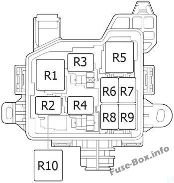
Engine Compartment Relay Box
| № | Relay |
|---|---|
| R1 | Headlight (H-LP) |
| R2 | From May 2015: Stop light (STOP LP) |
| R3 | Dimmer (DIM) |
| R4 | Normal: Electric Cooling Fan (FAN NO.1) |
| R5 | Multi-mode manual transmission (MMT) |
| R6 | Front fog light (FR FOG) |
| R7 | Horn |
| R8 | Daytime running light system (DRL) |
| R9 | Air conditioner compressor clutch (MG CLUTCH) |
| R10 | Tropic: Electric Cooling Fan (FAN NO.1) |


