

See other Toyota Aygo:

Fuse Layout Toyota Aygo 2005-2014
Contents

Cigar lighter (power outlet) fuse in the Toyota Aygo is the fuse #11 “ACC” in the Instrument panel fuse box.
Table of Contents
Passenger Compartment Fuse Box
Passenger Compartment Fuse Box
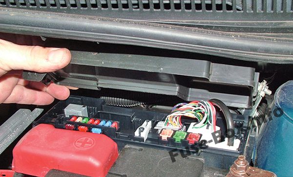
Fuse box location
Left-hand drive vehicles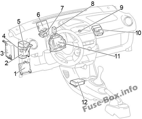
Right-hand drive vehicles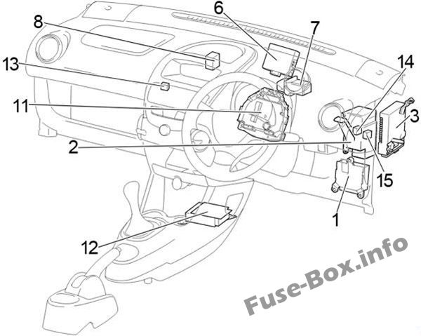
- Power Steering ECU
- Center Connector
- Multi-mode Manual Transmission ECU
- Power Window Relay
- LHD:
Before Feb. 2012: Tail Lamp Relay
From Feb. 2012: Rear Fog Lamp Relay - Door Control ECU with Receiver
- Relay Box No.1
- A/C Amplifier
- LHD: Fog Lamp Relay
- LHD: Running Light Relay
- Fuse Box
- Airbag Sensor Assembly Center
- RHD: Relay Box No.2
- RHD:
Before Feb. 2012: Ignition Relay (IG)
From Feb. 2012: Power Window Relay - RHD:
Before Feb. 2012: Power Window Relay
From Feb. 2012: Rear Fog Lamp Relay
The fuse box is located behind the steering wheel.
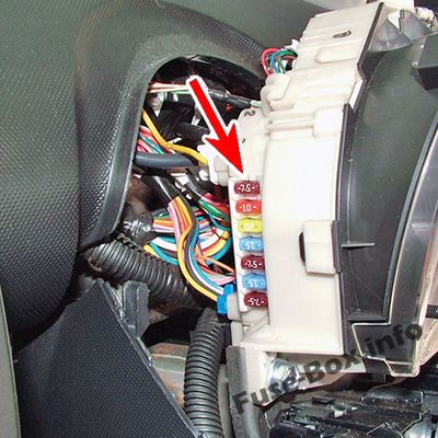
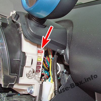
Remove the meter cover screws, by using a Phillips-head screwdriver. If the steering lock is engaged, please disengage it.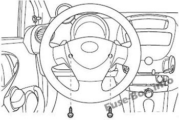
Remove the bottom screw of the tachometer, and lift and pull up on the tachometer.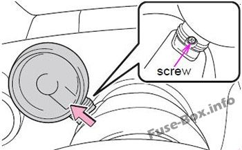
Pull the meter cover forward, lift up, and remove the meter cover.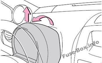
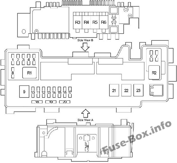
Fuse box diagram
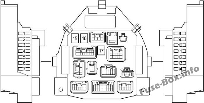
Assignment of the fuses in the passenger compartment
| № | Name | Amp | Circuit |
|---|---|---|---|
| 1 | STOP | 10 | Stop lights, high mounted stop light, anti-lock brake system, multi-mode manual transmission |
| 2 | D/L | 25 | Power door lock system, wireless remote control system |
| 3 | DEF | 20 | Rear window defogger |
| 4 | TAIL | 7.5 | Daytime running light system, tail lights, license plate lights, position lights, headlight beam level control system, instrument panel lights |
| 5 | OBD | 7.5 | On-board diagnosis system |
| 6 | ECU-B | 7.5 | Multi-mode manual transmission, daytime running light system, vehicle stability control system, gauges and meters, rear fog light |
| 7 | – | – | – |
| 8 | ECU-IG | 7.5 | Anti-lock brake system, vehicle stability control system, electric power steering system, electric cooling fan |
| 9 | BACK UP | 10 | Back-up lights, power door lock system, wireless remote control system, power windows, rear window defogger, tachometer, air conditioning system, heater system |
| 10 | WIP | 20 | Windshield wiper and washer, rear window wiper and washer |
| 11 | ACC | 15 | Power outlet, audio system |
| 12 | IG1 | 7.5 | Windshield wiper and washer, rear window wiper and washer, anti-lock brake system, electric power steering system, electric cooling fan, back-up lights, power door lock system, wireless remote control system, power windows, rear window defogger, tachometer, air conditioning system, heater system |
| 13 | IG2 | 15 | Multiport fuel injection system/sequential multiport fuel injection system, SRS airbag system, gauges and meters, daytime running light system, multi-mode manual transmission |
| 14 | A/C | 7.5 | Air conditioning system, power heater |
| 15 | AM1 | 40 | “ACC”, “WIP”, “ECU-IG”, “BACK UP” fuses |
| 16 | PWR | 30 | Power windows |
| 17 | HTR | 40 | Heater system, air conditioning system, “A/C” fuse |
Relay Box №1
Left-hand drive vehicles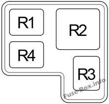
Right-hand drive vehicles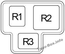
| № | Relay |
|---|---|
| R1 | Accessory (ACC) |
| R2 | Heater (HTR) |
| R3 | Rear window defogger (DEF) |
| R4 | LHD: Ignition (IG) |
Relay Box №2
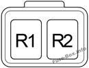
| № | Relay |
|---|---|
| R1 | Ignition (IG) |
| R2 | Fog light (FOG) |
Engine Compartment Fuse Box
Engine Compartment Fuse Box
Fuse box location
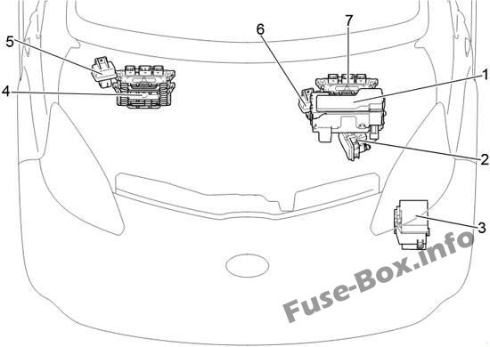
- Fuse Box
- Skid Control ECU with Actuator
- Relay Box
- LHD: Engine ECU
- LHD: Glow Plug Relay
- RHD: Glow Plug Relay
- RHD: Engine ECU
Fuse box diagram
Assignment of the fuses in the Engine Compartment
| № | Name | Amp | Designation |
|---|---|---|---|
| 1 | EFI NO.4 | 15 | 2WZ-TV: Multiport fuel injection system/sequential multiport fuel injection system |
| 2 | H-LP RH (HI) | 10 | Before Feb. 2012: Right-hand headlights |
| 2 | DRL | 5 | From Feb. 2012: Daytime running lights |
| 3 | H-LP LH (HI) | 10 | Before Feb. 2012: Left-hand headlights, gauges and meters |
| 3 | FR FOG | 20 | From Feb. 2012: Front fog lights |
| 4 | H-LP RH (LO) | 10 | Before Feb. 2012: Right-hand headlights |
| 4 | H-LP LH | 10 | From Feb. 2012: Left-hand headlights |
| 5 | H-LP LH (LO) | 10 | Before Feb. 2012: Left-hand headlights, gauges and meters |
| 5 | H-LP RH | 10 | From Feb. 2012: Right-hand headlights |
| 6 | STA | 7.5 | 1KR-FE: Multi-mode manual transmission, multiport fuel injection system/sequential multiport fuel injection system |
| 6 | FAN NO.2 | 7.5 | 2WZ-TV: Electric cooling fan |
| 7 | EFI NO.2 | 7.5 | Multiport fuel injection system/sequential multiport fuel injection system, multi-mode manual transmission |
| 8 | EFI NO.3 | 10 | 2WZ-TV: Multiport fuel injection system/sequential multiport fuel injection system, electric cooling fan |
| 8 | MET | 5 | Gauges and meters |
| 9 | AMT | 50 | 1KR-FE: Multi-mode manual transmission |
| 9 | RADIATOR FAN | 50 | 2WZ-TV: Electric cooling fan |
| 10 | H-LP LH | 10 | without DRL: Left-hand headlights |
| 10 | DIMMER | 20 | Before Feb. 2012: with DRL: “H-LP LH (HI)”, “H-LP RH(HI)”, “H-LP LH (LO)”, “H-LP RH (LO)” fuses, daytime running light system |
| 10 | SUB-LP | 30 | From Feb. 2012: with DRL: “DRL”, “FOG FR” fuses |
| 11 | VSC NO.2 | 30 | Anti-lock brake system and vehicle stability control system |
| 11 | ABS NO.2 | 25 | without VSC: Anti-lock brake system |
| 12 | AM 2 | 30 | Starting system, “IGl”, “IG2”, “STA” fuses |
| 13 | HAZARD | 10 | Turn signal lights, emergency flashers, gauges and meters |
| 14 | H-LP RH | 10 | Before Feb. 2012: Right-hand headlights |
| 14 | H-LP MAIN | 20 | From Feb. 2012: “H-LP LH”, “H-LP RH” fuses |
| 15 | DOME | 15 | Gauges and meters, interior light, audio system, tachometer |
| 16 | EFI | 15 | 1KR-FE: Electric cooling fan, multiport fuel injection system/sequential multiport fuel injection system |
| 16 | EFI | 25 | 2WZ-TV: Electric cooling fan, multiport fuel injection system/sequential multiport fuel injection system |
| 17 | HORN | 10 | Horn |
| 18 | – | 7.5 | Spare fuse |
| 19 | – | 10 | Spare fuse |
| 20 | – | 15 | Spare fuse |
| 21 | RADIATOR | 40 | Tropic: Electric cooling fan |
| 21 | 30 | Normal: Electric cooling fan | |
| 22 | VSC NO.1 | 50 | Anti-lock brake system and vehicle stability control system |
| 22 | ABS NO.1 | 40 | without VSC: Anti-lock brake system |
| 23 | EMPS | 50 | Electric power steering system |
| 24 | ALTERNATOR | 120 | 1KR-FE: Charging system, “EPS”, “ABS (without vehicle stability control system)”, “VSC (with vehicle stability control system)”, “RADIATOR”, “AM1”, “HTR”, “PWR”, “D/L”, “DEF”, ’TAIL”, “STOP”, “OBD”, “ECU-B” fuses |
| 25 | – | – | EBD Resistor |
| Relay | |||
| R1 | Air conditioner compressor clutch (A/C MAG) | ||
| R2 | Starter (ST) | ||
| R3 | Engine control unit (EFI MAIN) | ||
| R4 | 1KR-FE: Fuel pump (C/OPN) | ||
| R5 | Horn | ||
| R6 | Electric cooling fan (FAN NO.1) |
Relay Box
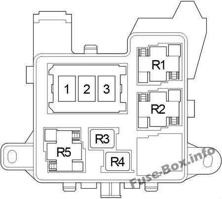
| № | Name | Amp | Circuit |
|---|---|---|---|
| 1 | – | – | – |
| 2 | PTC2 | 80 | PTC Heater |
| 3 | PTC1 | 80 | PTC Heater |
| Relay | |||
| R1 | Multi-mode manual transmission (MMT) PTC heater (PTC1) | ||
| R2 | PTC heater (PTC2) | ||
| R3 | – | ||
| R4 | Before Feb. 2012: Headlight (H-LP) From Feb. 2012: Daytime running light (DRL) |
||
| R5 | Dimmer (DIM) |


