


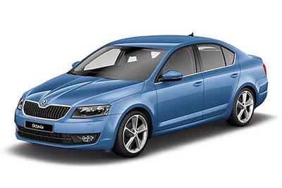
Fuse Layout Skoda Octavia 2013-2016
Contents
Cigar lighter (power outlet) fuses in the Skoda Octavia are the fuses #40 (12-Volt power socket) and #46 (230-Volt power socket) in the Instrument panel fuse box.
Table of Contents
Colour coding of fuses
| Fuse colour | Maximum amperage |
|---|---|
| light brown | 5 |
| dark brown | 7.5 |
| red | 10 |
| blue | 15 |
| yellow/blue | 20 |
| white | 25 |
| green/pink | 30 |
| orange/green | 40 |
| red | 50 |
Fuses in the dash panel (version 1 – 2013, 2014)
Fuse box location
Left-hand drive vehicles:
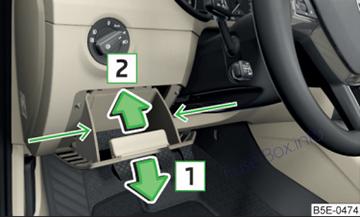
On left-hand drive vehicles, the fuse box is located behind the storage compartment in the left-hand section of the dash panel.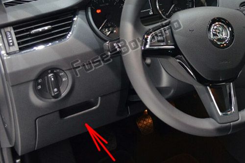
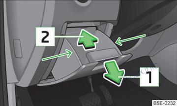
Open the storage compartment.
Grab hold of the storage compartment in the area of the arrows.
Fold out the storage compartment by pulling in the direction of arrow 1.
Replace the appropriate fuse.
Fold back the storage compartment by pressing into the secured position in the dash panel in the direction of the arrow 2.
Right-hand drive vehicles:
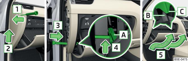
On right-hand drive vehicles, it is located on the front passenger’s side behind the glove box in the left-hand section of the dash panel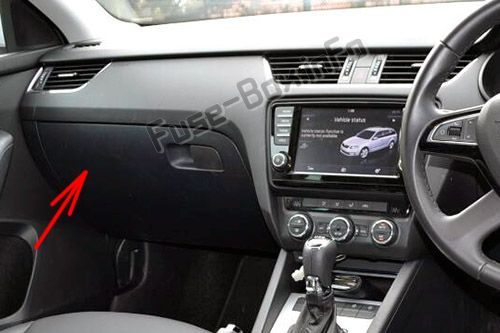
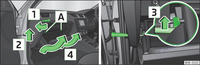
Removing the storage compartment:
- Insert a screwdriver under the side cover.
- Unlock the cover in the direction of the arrow 1.
- Push the cover out in the direction of the arrow 2.
- Open the storage compartment.
- Unlock the brake rod of the storage compartment in the direction of the arrow 3 with the screwdriver.
- Remove the storage compartment in the direction of the arrow 4.
- Replace the appropriate fuse.
Installing the storage compartment:
- Pull in the storage compartment behind the brackets A.
- Push in the storage compartment in the opposite direction of the arrow 4.
- Insert the brake rod and lock it against the arrow 3 with a screwdriver.
- Push in the side cover against the direction of the arrow 2.
- Press the side cover fully against the direction of the arrow 1.
Fuse box diagram
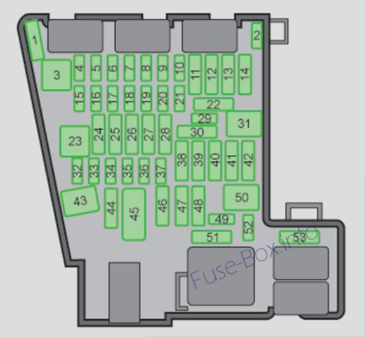
Fuses assignment in the dash panel (version 1 – 2013, 2014)
| No. | Power consumer |
|---|---|
| 1 | Not assigned |
| 2 | Not assigned |
| 3 | Not assigned |
| 4 | Not assigned |
| 5 | Data bus control unit |
| 6 | Alarm sensor |
| 7 | Control unit for the air conditioning system, heating, receiver for remote control for the auxiliary heating, selector lever for the automatic gearbox, relay for the rear window heater, replay for the windscreen heater |
| 8 | Light switch, rain sensor, diagnostic socket |
| 9 | Haldex clutch |
| 10 | Touchscreen |
| 11 | Heated rear seats |
| 12 | Radio |
| 13 | Belt tensioner – driver’s side |
| 14 | Air blower for air conditioning,heating |
| 15 | Electric steering lock |
| 16 | Signal amplifier for telephone, telephone preinstallation |
| 17 | Instrument cluster |
| 18 | Not assigned |
| 19 | KESSY control unit |
| 20 | Steering wheel module |
| 21 | Not assigned |
| 22 | Luggage compartment door opening |
| 23 | Light – right |
| 24 | Panorama roof |
| 25 | Control unit for central locking front door right, power windows – left |
| 26 | Heated front seats |
| 27 | Music amplifier |
| 28 | Towing device |
| 29 | Not assigned |
| 30 | Not assigned |
| 31 | Headlight – left |
| 32 | Parking aid (Park Assist) |
| 33 | Airbag |
| 34 | TCS button, ESC, tyre control display, pressure sensor for air-conditioning, reverse light switch, dimming rear view mirror, START-STOP button, telephone preinstallation, control for heating of rear seats, sensor for air-conditioning, 230 V power socket, sound actuator |
| 35 | Headlight, headlamp beam adjustment, diagnostic connector, camera, radar |
| 36 | Headlight right |
| 37 | Headlight left |
| 38 | Towing device |
| 39 | Control unit for central locking front door – right, power windows -front and rear right |
| 40 | 12-Volt power socket |
| 41 | CNG relay |
| 42 | Control unit for central locking rear door – left, right, headlight cleaning system, windscreen wipers |
| 43 | Visor for gas discharge bulbs, interior lighting |
| 44 | Towing device |
| 45 | Control unit for control of seat adjustment |
| 46 | 230-Volt power socket |
| 47 | Rear window wiper |
| 48 | Not assigned |
| 49 | Coil on starter relay, clutch pedal switch |
| 50 | Not assigned |
| 51 | Belt tensioner – front passenger side |
| 52 | Not assigned |
| 53 | Relay for rear window heater |
Fuses in the dash panel (version 2 – 2015, 2016)
Fuse box location
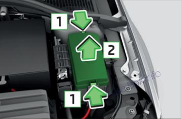
Left-hand drive vehicles:
On left-hand drive vehicles, it is located behind the storage compartment in the left-hand section of the dash panel.
Open the storage compartment.
Grab hold of the storage compartment in the area of the arrows.
Fold out the storage compartment by pulling in the direction of arrow 1.
Replace the appropriate fuse.
Fold back the storage compartment by pressing into the secured position in the dash panel in the direction of the arrow 2.
Right-hand drive vehicles:
On right-hand drive vehicles, the fuse box is located on the front passenger’s side behind the glove box in the left-hand section of the dash panel
Removing the storage compartment:
- Insert a screwdriver under the side cover.
- Unlock the cover in the direction of the arrow 1.
- Push the cover out in the direction of the arrow 2.
- Open the storage compartment.
- Insert a screwdriver from the side into the dash panel in the direction of arrow 3.
- Use the screwdriver to unlock the brake rod A of the storage compartment in the direction of arrow 4.
- Remove the storage compartment in the direction of arrow 5.
- Remove the plastic clip under the cover of the fuse box in the engine room.
- Place the clip onto the respective fuse and pull the fuse out.
- Insert a new fuse.
- Replace the bracket at the original position.
Installing the storage compartment:
- Move the stop buffer B of the storage compartment behind the brackets C.
- Push in the storage compartment in the opposite direction of the arrow 5.
- Insert the brake rod and lock it against the arrow 4 with a screwdriver.
- Push in the side cover against the direction of the arrow 2.
- Press the side cover fully against the direction of the arrow 1.
Fuse box diagram
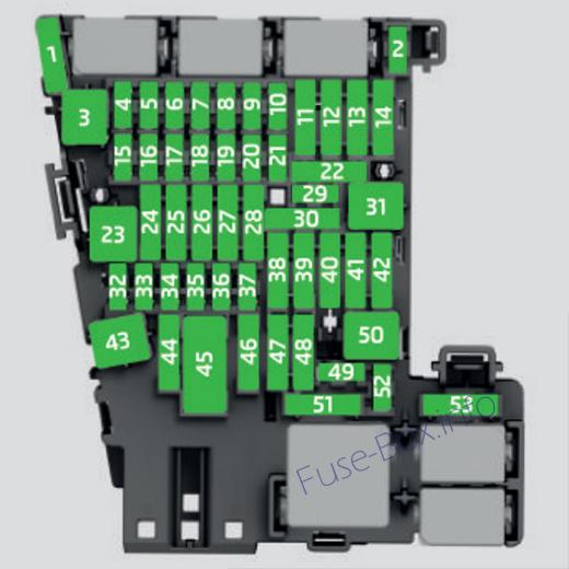
Fuse assignment in the dash panel (version 2 – 2015, 2016)
| No. | Consumer |
|---|---|
| 1 | Not assigned |
| 2 | Not assigned |
| 3 | Not assigned |
| 4 | Not assigned |
| 5 | Data bus control unit |
| 6 | Alarm sensor |
| 7 | Control unit for the air conditioning system, heating, receiver for remote control for the auxiliary heating, selector lever for the automatic gearbox, relay for the rear window heater, replay for the windscreen heater |
| 8 | Light switch, rain sensor, diagnostic socket |
| 9 | Haldex clutch |
| 10 | Touchscreen |
| 11 | Heated rear seats |
| 12 | Radio |
| 13 | Belt tensioner – driver’s side |
| 14 | Air blower for air conditioning f heating |
| 15 | Electric steering lock |
| 16 | Signal amplifier for telephone, telephone preinstallation |
| 17 | Instrument cluster |
| 18 | Not assigned |
| 19 | KESSY control unit |
| 20 | Operating lever underneath the steering wheel |
| 21 | Not assigned |
| 22 | Towing hitch – contact in the socket |
| 23 | Light – right |
| 24 | Panorama roof |
| 25 | Control unit for central locking front door right, power windows -left |
| 26 | Heated front seats |
| 27 | Music amplifier |
| 28 | Towing hitch – left light |
| 29 | CNG relay |
| 30 | Not assigned |
| 31 | Headlight – left |
| 32 | Parking aid (Park Assist) |
| 33 | Airbag switch for hazard warning lights |
| 34 | TCS, ESC button, tyre control display, pressure sensor for air-conditioning, reverse light switch, interior mirror with automatic dimming, START-STOP button, telephone preinstallation, control for heating of rear seats, sensor for air-conditioning, 230 V power socket, sport-sound generator |
| 35 | Headlight, headlamp beam adjustment, diagnostic connector, camera, radar |
| 36 | Headlight right |
| 37 | Headlight left |
| 38 | Towing hitch – right light |
| 39 | Control unit for central locking front door – right, power windows -front and rear right |
| 40 | 12-Volt power socket |
| 41 | Not assigned |
| 42 | Control unit for central locking rear door – left, right, headlight cleaning system, windscreen wipers |
| 43 | Visor for gas discharge bulbs, interior lighting |
| 44 | Towing hitch – contact in the socket |
| 45 | Control unit for control of seat adjustment |
| 46 | 230-Volt power socket |
| 47 | Rear window wiper |
| 48 | Not assigned |
| 49 | Coil on starter relay, clutch pedal switch |
| 50 | Opening the boot lid |
| 51 | Belt tensioner – front passenger side |
| 52 | Not assigned |
| 53 | Relay for rear window heater |
Fuses in the engine compartment
Fuse box location
The fuses are located under the cover in the engine compartment on the left.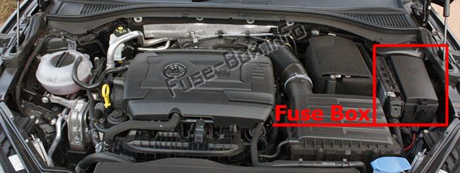
Fuse box diagram (version 1 – 2013, 2014)
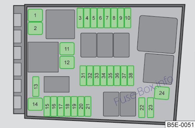
Fuses assignment in engine compartment (version 1 – 2013, 2014)
| No. | Power consumer |
|---|---|
| F1 | Control unit for ESC |
| F2 | Control unit for ESC, ABS |
| F3 | Engine control unit |
| F4 | Engine control unit, relay for electric auxiliary heating |
| F5 | Engine components |
| F6 | Brake sensor, engine components |
| F7 | Coolant pump, engine components |
| F8 | Lambda probe |
| F9 | Ignition, control unit for glow plug system, engine components |
| F10 | Control unit for fuel pump, ignition |
| F11 | Electrical auxiliary heating system |
| F12 | Electrical auxiliary heating system |
| F13 | Control unit for automatic gearbox |
| F14 | Windscreen heater – left |
| F15 | Horn |
| F16 | Ignition, fuel pump |
| F17 | Control unit for ABS, ESC, engine control unit |
| F18 | Data bus control unit |
| F19 | Windscreen wipers |
| F20 | Alarm |
| F21 | ABS |
| F22 | Engine control unit |
| F23 | Starter |
| F24 | Electrical auxiliary heating system |
| F31 | Not assigned |
| F32 | Not assigned |
| F33 | Not assigned |
| F34 | Windscreen heater – right |
| F35 | Not assigned |
| F36 | Not assigned |
| F37 | Control unit for auxiliary heating |
| F38 | Not assigned |
Fuse box diagram (version 2 – 2015, 2016)
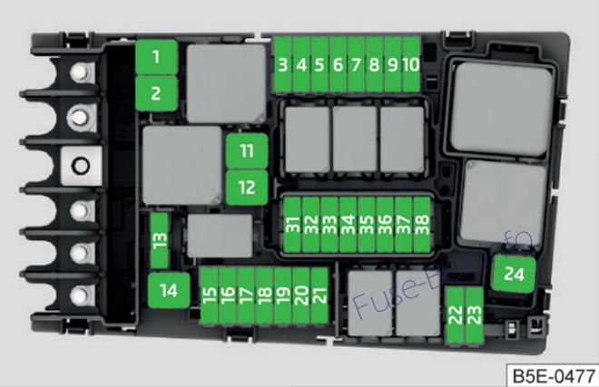
Fuses assignment in engine compartment (version 2 – 2015, 2016)
| No. | Consumer |
|---|---|
| 1 | Control unit for ESC, ABS |
| 2 | Control unit for ESC, ABS |
| 3 | Engine control unit |
| 4 | Radiator fan, oil temperature sensor, air volume sensor, control valve for fuel pressure, relay for electrical auxiliary heating |
| 5 | Coil of the relay for the ignition system, coil of the CNG relay |
| 6 | Brake sensor |
| 7 | Coolant pump, radiator shutter |
| 8 | Lambda probe |
| 9 | Ignition, control unit for preheating system |
| 10 | Control unit for fuel pump, ignition |
| 11 | Electrical auxiliary heating system |
| 12 | Electrical auxiliary heating system |
| 13 | Control unit for automatic gearbox |
| 14 | Not assigned |
| 15 | Horn |
| 16 | Ignition, fuel pump |
| 17 | Control unit for ABS, ESC, engine control unit |
| 18 | Data bus control unit |
| 19 | Windscreen wipers |
| 20 | Alarm |
| 21 | Windscreen heater – left |
| 22 | Engine control unit |
| 23 | Starter |
| 24 | Electrical auxiliary heating system |
| 31 | Not assigned |
| 32 | Not assigned |
| 33 | Not assigned |
| 34 | Windscreen heater – right |
| 35 | Not assigned |
| 36 | Not assigned |
| 37 | Control unit for auxiliary heating |
| 38 | Not assigned |


