

Fuse Layout Skoda Yeti 2009-2017
Contents
Cigar lighter (power outlet) fuses in the Skoda Yeti are the fuses #26 (Power socket in the luggage compartment) and #30 (Front and rear lighters) in the Instrument panel fuse box.
Table of Contents
Colour coding of fuses
| Fuse colour | Maximum amperage |
|---|---|
| light brown | 5 |
| dark brown | 7.5 |
| red | 10 |
| blue | 15 |
| yellow | 20 |
| white | 25 |
| green | 30 |
| orange | 40 |
| red | 50 |
Fuse box location
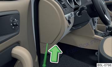
Passenger compartment
The fuse box is located on the side of the dash panel behind a cover.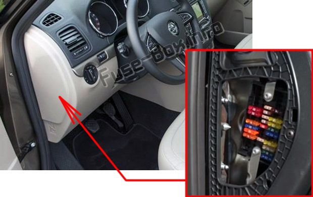
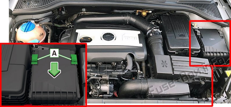
Fuse box in the engine compartment
Fuse box diagrams
2009, 2010
Fuse box in the dash panel
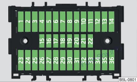
Assignment of the fuses in the dash panel (2009, 2010)
| No. | Power consumer | Amperes |
|---|---|---|
| 1 | Heating of the gearbox ventilation (diesel engine) | 10 |
| 1 | Control unit for automatic gearbox DQ200 | 10 |
| 2 | Towing device | 20 |
| 3 | Towing device | 15 |
| 4 | Not assigned | |
| 5 | Air blower for heating, radiator fan, air conditioning system, Climatronic | 40 |
| 6 | Rear window wiper | 15 |
| 7 | Not assigned | |
| 8 | Towing device | 15 |
| 9 | Central control unit – interior lights | 10 |
| 10 | Rain sensor, light switch, diagnostic socket | 10 |
| 11 | Left side cornering lights | 10 |
| 12 | Right side cornering lights | 10 |
| 13 | Radio, changer for mobile navigation | 15 |
| 14 | Towing device | 5 |
| 15 | Light switch | 5 |
| 16 | Heatable washing nozzles, regulator for seat heating | 5 |
| 17 | Control unit for headlamp beam adjustment and headlight swivel | 5 |
| 18 | Diagnostic socket, engine control unit, brake sensor | 10 |
| 19 | Control unit for ABS, ESP, switch for tyre air pressure control, control unit for parking aid, switch for Offroad mode | 5 |
| 20 | Switch and control unit for airbag | 5 |
| 21 | WIV, parking light, dimming mirrors, pressure sensor, telephone preinstallation, air mass meter | 5 |
| 22 | Instrument cluster, control unit for electromechanical power steering, Haldex | 5 |
| 23 | Central locking system and bonnet lid | 15 |
| 24 | Rear power window | 30 |
| 25 | Rear window heater | 25 |
| 25 | Rear window heater, Auxiliary heating (auxiliary heating and ventilation) | 30 |
| 26 | Power socket in the luggage compartment | 20 |
| 27 | Electric sliding/tilting roof, electric sun screen | 30 |
| 28 | Fuel pump relay, control unit for fuel pump, injection valves | 15 |
| 29 | Front power window | 30 |
| 30 | front and rear lighter | 20 |
| 31 | Headlight cleaning system | 20 |
| 32 | Front seat heating | 20 |
| 33 | Heating, Climatic, Climatronic | 7,5 |
| 34 | Alarm, spare horn | 5 |
| 35 | Control unit for automatic gearbox DQ200 | 10 |
| 36 | Not assigned |
Fuse box in the engine compartment (version 1)
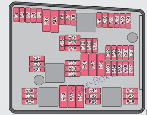
Fuses assignment in engine compartment (version 1, 2009, 2010)
| No. | Power consumer | Amperes |
|---|---|---|
| F1 | Central control unit, right main headlight, right rear light unit | 30 |
| F2 | Valves for ABS | 20 |
| F3 | Not assigned | |
| F4 | Measuring circuit | 5 |
| F5 | Horn | 15 |
| F6 | Not assigned | |
| F7 | Valve for fuel dosing | 15 |
| F8 | Not assigned | |
| F9 | Activated charcoal filter, exhaust gas recirculation valve | 10 |
| F10 | Leakage diagnosis pump | 10 |
| F11 | Lambda probe upstream of catalytic converter, engine control unit | 10 |
| F12 | Lambda probe downstream of catalytic converter | 10 |
| F13 | Control unit for automatic gearbox | 15 |
| F14 | Not assigned | |
| F15 | Coolant pump | 10 |
| F16 | Not assigned | |
| F17 | Instrument cluster, windshield wiper lever and turn signal light lever | 5 |
| F18 | Audio amplifier (sound system) | 30 |
| F19 | Radio | 15 |
| F20 | Phone | 5 |
| F21 | Not assigned | |
| F22 | Not assigned | |
| F23 | Engine control unit | 10 |
| F24 | Control unit for CAN databus | 5 |
| F25 | Not assigned | |
| F26 | Not assigned | |
| F27 | Not assigned | |
| F28 | Engine control unit | 15 |
| F29 | Actuation for coolant pump after-running | 5 |
| F30 | Control unit for auxiliary heating | 20 |
| F31 | Front window wiper | 30 |
| F32 | Not assigned | |
| F33 | Not assigned | |
| F34 | Not assigned | |
| F35 | Not assigned | |
| F36 | Not assigned | |
| F37 | Not assigned | |
| F38 | Radiator fan, valves | 10 |
| F39 | Clutch pedal switch, brake pedal switch | 5 |
| F40 | Ignition coils | 20 |
| F41 | Not assigned | |
| F42 | Actuation of fuel pump | 5 |
| F43 | Not assigned | |
| F44 | Not assigned | |
| F45 | Not assigned | |
| F46 | Not assigned | |
| F47 | Central control unit, left main headlight, left rear light unit | 30 |
| F48 | Pump for ABS | 40 |
| F49 | Power supply for terminal 15 (ignition on) | 40 |
| F50 | Not assigned | |
| F51 | Not assigned | |
| F52 | Power supply relay – terminal X | 40 |
| F53 | Accessory equipment | 50 |
| F54 | Not assigned |
Fuse box in the engine compartment (version 2)
Fuses assignment in engine compartment (version 2, 2009)
| No. | Power consumer | Amperes |
|---|---|---|
| F1 | Not assigned | |
| F2 | Control unit for automatic gearbox DQ 200 | 30 |
| F3 | Measuring circuit | 5 |
| F4 | Valves for ABS | 30/20 |
| F5 | Control unit for automatic gearbox | 15 |
| F6 | Instrument duster, windshield wiper lever and turn signal light lever | 5 |
| F7 | Power suppy terminal 15, Starter | 40 |
| F8 | Radio | 15 |
| F9 | Phone | 5 |
| F10 | Engine control unit. Main relay | 5/10 |
| F11 | Control unit for auxiliary heating | 20 |
| F12 | Control unit for CAN databus | 5 |
| F13 | Engine control unit | 15/30 |
| F14 | Ignition | 20 |
| F15 | Lambda probe, NOx -sensor, Fuel pump relay | 15 |
| F15 | Glow plug system relay | 5 |
| F16 | Central control unit right main headlight, right rear light unit | 30 |
| F17 | Horn | 15 |
| F18 | Amplifier for digital sound processor | 30 |
| F19 | Front window wiper | 30 |
| F20 | Water pump | 10 |
| F21 | Lambda probe | 10/15 |
| F22 | Clutch pedal switch, brake pedal switch | 5 |
| F23 | Secondary air pump | 5 |
| F23 | Air mass meter | 10 |
| F23 | Fuel high pressure pump | 15 |
| F24 | Activated charcoal filter, exhaust gas recirculation valve | 10 |
| F25 | Pump for ABS | 30/40 |
| F26 | Central control unit, left main headlight, left rear light unit | 30 |
| F27 | Secondary air pump | 40 |
| F27 | Glow plug system | 50 |
| F28 | Not assigned | |
| F29 | Power supply terminal 30 | 50 |
| F30 | Terminal X | 40 |
Fuses assignment in engine compartment (version 2, 2010)
| No. | Power consumer | Amperes |
|---|---|---|
| F1 | Not assigned | |
| F2 | Control unit for automatic gearbox DQ 200 | 30 |
| F3 | Measuring circuit | 5 |
| F4 | ABS control unit | 20 |
| F5 | Control unit for automatic gearbox | 15 |
| F6 | Instrument cluster, windshield wiper lever and turn signal light lever | 5 |
| F7 | Power suppy terminal 15, Starter | 40 |
| F8 | Radio | 15 |
| F9 | Phone | 5 |
| F10 | Engine control unit, Main relay | 5/10 |
| F11 | Control unit for auxiliary heating | 20 |
| F12 | Control unit for CAN databus | 5 |
| F13 | Engine control unit | 15/30 |
| F14 | Ignition | 20 |
| F15 | Lambda probe, fuel pump relay | 15 |
| F15 | glow plug system relay | 5 |
| F16 | Central control unit, right main headlight, right rear light unit | 30 |
| F17 | Horn | 15 |
| F18 | Amplifier for digital sound processor | 30 |
| F19 | Front window wiper | 30 |
| F20 | Control valve for fuel pressure | 20 |
| F21 | Lambda probe | 10/15 |
| F22 | Clutch pedal switch, brake pedal switch | 5 |
| F23 | Coolant pump | 5 |
| F23 | charge pressure control solenoid valve, changeover valve for radiator | 10 |
| F24 | Activated charcoal filter, exhaust gas recirculation valve | 10 |
| F25 | ABS control unit | 40 |
| F26 | Central control unit, left main headlight, left rear light unit | 30 |
| F27 | Glow plug system | 50 |
| F28 | Not assigned | |
| F29 | Power supply of the interior | 50 |
| F30 | Terminal X | 40 |
2011
Fuse box in the dash panel
Assignment of the fuses in the dash panel (2011)
| No. | Power consumer | Amperes |
|---|---|---|
| 1 | Heating of the gearbox ventilation (diesel engine) | 10 |
| 1 | Control unit for automatic gearbox DQ200 | 10 |
| 2 | Towing device | 20 |
| 3 | Towing device | 15 |
| 4 | Instrument cluster, windshield wiper lever, turn signal light lever | 5 |
| 5 | Air blower for heating, radiator fan, air conditioning system, Climatronic | 40 |
| 6 | Rear window wiper | 15 |
| 7 | Phone | 5 |
| 8 | Towing device | 15 |
| 9 | Central control unit – Interior lighting Rear fog light | 10 |
| 10 | Rain sensor, light switch, diagnostic socket | 10 |
| 11 | Left side cornering lights | 10 |
| 12 | Right side cornering lights | 10 |
| 13 | Radio, changer for mobile navigation | 15 |
| 14 | Towing device | 5 |
| 15 | Light switch | 5 |
| 16 | Heated windscreen washer nozzles | 5 |
| 17 | Control unit for headlamp beam adjustment and headlight swivel | 5 |
| 18 | Diagnostic socket, engine control unit, brake sensor | 10 |
| 19 | Control unit for ABS, ESP, switch for tyre air pressure control, control unit for parking aid, switch for Offroad mode, start/stop button | 5 |
| 20 | Switch and control unit for airbag | 5 |
| 21 | WIV, parking light, dimming mirrors, pressure sensor, telephone preinstallation, air mass meter | 5 |
| 22 | Instrument cluster, control unit for electromechanical power steering, Haldex | 5 |
| 23 | Central locking system and bonnet lid | 15 |
| 24 | Rear power window | 30 |
| 25 | Rear window heater | 25 |
| 25 | Rear window heater, Auxiliary heating (auxiliary heating and ventilation) | 30 |
| 26 | Power socket in the luggage compartment | 20 |
| 27 | Electric sliding/tilting roof, electric sun screen | 30 |
| 28 | Fuel pump relay, control unit for fuel pump, injection valves | 15 |
| 29 | Front power window | 30 |
| 30 | front and rear lighter | 20 |
| 31 | Headlight cleaning system | 20 |
| 32 | Front seat heating, regulator for seat heating | 20 |
| 33 | Heating, Climatic, Climatronic | 7,5 |
| 34 | Alarm, spare horn | 5 |
| 35 | Control unit for automatic gearbox DQ200 | 10 |
| 36 | Not assigned |
Fuse box in the engine compartment
Fuses assignment in engine compartment (2011)
| No. | Power consumer | Amperes |
|---|---|---|
| F1 | Not assigned | |
| F2 | Control unit for automatic gearbox DQ 200 | 30 |
| F3 | Measuring circuit | 5 |
| F4 | ABS control unit | 20 |
| F5 | Control unit for automatic gearbox | 15 |
| F6 | Instrument cluster, windshield wiper lever and turn signal light lever | 5 |
| F7 | Power suppy terminal 15, Starter | 40 |
| F8 | Radio | 15 |
| F9 | Phone | 5 |
| F10 | Engine control unit. Main relay | 5/10 |
| F11 | Control unit for auxiliary heating | 20 |
| F12 | Control unit for CAN databus | 5 |
| F13 | Engine control unit | 15/30 |
| F14 | Ignition | 20 |
| F15 | Lambda probe, fuel pump relay glow plug system relay | 15 5 |
| F16 | Central control unit, right main headlight, right rear light unit | 30 |
| F17 | Horn | 15 |
| F18 | Amplifier for digital sound processor | 30 |
| F19 | Front window wiper | 30 |
| F20 | Control valve for fuel pressure | 10/20 |
| F21 | Lambda probe | 10/15/20 |
| F22 | Clutch pedal switch, brake pedal switch | 5 |
| F23 | Coolant pump | 5 |
| F23 | Charge pressure control solenoid valve, changeover valve for radiator | 10 |
| F23 | Fuel high pressure pump | 15 |
| F24 | Activated charcoal filter, exhaust gas recirculation valve | 10 |
| F25 | ABS control unit | 40 |
| F26 | Central control unit, left main headlight, left rear light unit | 30 |
| F27 | Glow plug system | 50 |
| F28 | Windscreen heater | 50 |
| F29 | Power supply of the interior | 50 |
| F30 | Terminal X | 50 |
2012, 2013
Fuse box in the dash panel
Assignment of the fuses in the dash panel (2012, 2013)
| No. | Power consumer |
|---|---|
| 1 | Heating of the gearbox ventilation (diesel engine) • Control unit for automatic gearbox DSG |
| 2-3 | Towing device |
| 4 | Instrument duster, windshield wiper lever, turn signal light lever, camera |
| 5 | Air blower for heating, radiator fan, air conditioning system, Clima-tronic |
| 6 | Rear window wiper |
| 7 | Phone |
| 8 | Towing device |
| 9 | Vehicle voltage control unit • interior lights Rear fog light |
| 10 | Rain sensor, light switch, diagnostic socket |
| 11 | Left side cornering lights |
| 12 | Right side cornering lights |
| 13 | Radio, changer for mobile navigation |
| 14 | Towing device |
| 15 | Light switch |
| 16 | Haldex |
| 17 | Control unit for headlamp beam adjustment and headlight swivel |
| 18 | Diagnostic socket, engine control unit, brake sensor |
| 19 | Control unit for ABS, ESP, switch for tyre air pressure control, control unit for parking aid, switch for OFF ROAD mode, START STOP button |
| 20 | Switch and airbag control unit |
| 21 | WIV, tail light, dimming mirrors, pressure sensor, telephone preinstallation, air mass meter |
| 22 | Instrument cluster, control unit for electromechanical power steering |
| 23 | Central locking system and bonnet lid |
| 24 | Rear power window |
| 25 | Rear window heater, auxiliary heating and ventilation |
| 26 | Power socket in the boot |
| 27 | Electric sliding/tilting roof, electric sun screen |
| 28 | Fuel pump, injection valves |
| 29 | Front power window |
| 30 | front and rear lighter |
| 31 | Headlight cleaning system |
| 32 | Front seat heating, regulator for seat heating |
| 33 | Heating, air conditioning, Climatronic, remote control for auxiliary heating |
| 34 | Alarm, spare horn |
| 35 | Control unit for automatic gearbox DSG |
| 36 | DVD |
Fuse box in the engine compartment
Fuses assignment in engine compartment (2012, 2013)
| No. | Power consumer |
|---|---|
| F1 | Not assigned |
| F2 | Control unit for automatic gearbox |
| F3 | Measuring circuit |
| F4 | ABS control unit |
| F5 | Control unit for automatic gearbox |
| F6 | Instrument duster, windscreen wiper lever, and turn signal lever |
| F7 | Power supply terminal 15, Starter |
| F8 | Radio |
| F9 | Phone |
| F10 | Engine control unit |
| F11 | Auxiliary heating and ventilation control unit |
| F12 | Data bus control unit |
| F13 | Engine control unit |
| F14 | Ignition |
| F15 | Lambda probe, fuel pump relay / Glow plug system |
| F16 | Vehicle voltage control unit, right headlight, right tail light |
| F17 | Horn |
| F18 | Amplifier for digital sound processor |
| F19 | Windscreen wipers |
| F20 | Control valve for fuel pressure |
| F21 | Lambda probe |
| F22 | Clutch pedal switch, brake pedal switch |
| F23 | Coolant pump / Charge pressure control solenoid valve, changeover valve for radiator / Fuel high pressure pump |
| F24 | Active charcoal filter, exhaust gas recirculation valve, radiator fan |
| F25 | ABS control unit |
| F26 | Vehicle voltage control unit, left headlight, left tail light |
| F27 | Glow Plug System |
| F28 | Windscreen heater |
| F29 | Power supply of the interior |
| F30 | Terminal X |
2014, 2015, 2016, 2017
Fuse box in the dash panel
Assignment of the fuses in the dash panel (2014-2017)
| No. | Consumer |
|---|---|
| 1 | Heating of the gearbox vent (diesel engine) / Control unit for DSG automatic gearbox |
| 2 | Towing hitch – left light |
| 3 | Towing hitch – right light |
| 4 | Instrument cluster control lever under the steering wheel, camera |
| 5 | Air blower for heating, radiator fan, air conditioning system, Clima-tronic |
| 6 | Rear window wiper |
| 7 | Phone |
| 8 | Towing hitch – contact in the socket |
| 9 | Vehicle voltage control unit – interior lights Rear fog light |
| 10 | Rain sensor, light switch, diagnostic socket |
| 11 | Left side cornering lights |
| 12 | Right side cornering lights |
| 13 | Radio, DVD |
| 14 | Central control unit, engine control unit |
| 15 | Light switch |
| 16 | Haldex |
| 17 | KESSY controller, steering wheel locking |
| 18 | Diagnostic socket, engine control unit, brake sensor, Haldex |
| 19 | Control unit for ABS, ESP, switch for tyre air pressure control, control unit for parking aid, switch for OFF ROAD mode, START STOP button |
| 20 | Switch and airbag control unit |
| 21 | WIV, tail lamp, dimming mirror, pressure sensor, telephone preparation, air mass sensor, control unit for headlight range control and headlight tilt |
| 22 | Instrument cluster controller for electro-mechanical power steering, control unit for data bus |
| 23 | Central locking system and bonnet lid |
| 24 | Rear power window |
| 25 | Rear window heater, auxiliary heating and ventilation |
| 26 | Power socket in the boot |
| 27 | Panorama window – sliding / tilting roof, electric sunblind |
| 28 | Fuel pump, injection valves |
| 29 | Front power window |
| 30 | front and rear lighter |
| 31 | Headlight cleaning system |
| 32 | Front seat heating, regulator for seat heating |
| 33 | Heating, air conditioning, Climatronic, remote control for auxiliary heating |
| 34 | Alarm, spare horn |
| 35 | Control unit for DSG automatic gearbox |
| 36 | Control unit for trailer detection |
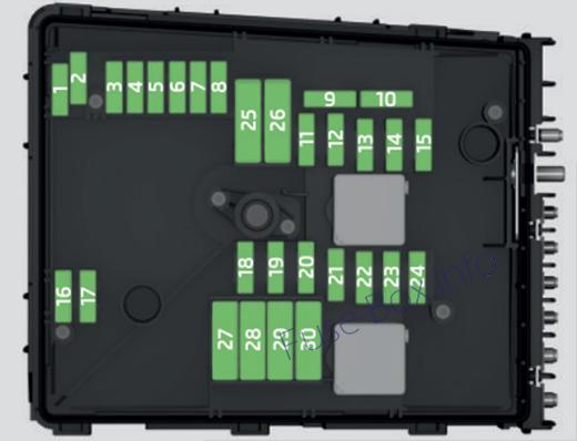
Fuse box in the engine compartment
Fuse assignment in engine compartment (2014-2017)
| No. | Consumer |
|---|---|
| 1 | Not assigned |
| 2 | Control unit for automatic gearbox |
| 3 | Battery data module |
| 4 | ABS control unit |
| 5 | Control unit for automatic gearbox |
| 6 | Not assigned |
| 7 | Power supply for terminal 15, starter |
| 8 | Radio, instrument cluster, telephone |
| 9 | Not assigned |
| 10 | Engine control unit |
| 11 | Auxiliary heating and ventilation control unit |
| 12 | Data bus control unit |
| 13 | Engine control unit |
| 14 | Ignition |
| 15 | Lambda probe, fuel pump / Glow plug system |
| 16 | Vehicle voltage control unit, right headlight, right tail light |
| 17 | Horn |
| 18 | Amplifier for digital sound processor |
| 19 | Windscreen wipers |
| 20 | Control valve for fuel pressure, high pressure pump |
| 21 | Lambda probe |
| 22 | Clutch pedal switch, brake pedal switch |
| 23 | Coolant pump Solenoid valve for charge pressure control, change-over valve for cooler / High-pressure fuel pump |
| 24 | Active charcoal filter, exhaust gas recirculation valve, radiator fan |
| 25 | ABS control unit |
| 26 | Vehicle voltage control unit, left headlight, left tail light |
| 27 | Glow plug system |
| 28 | Windscreen heater |
| 29 | Power to the internal fuse carrier |
| 30 | Terminal X |


