


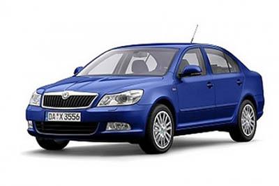
Fuse Layout Skoda Octavia 2009-2013
Contents
Cigar lighter (power outlet) fuses in the Skoda Octavia are the fuses #24 (Cigarette lighter) and #26 (Power socket in the luggage compartment) in the Instrument panel fuse box.
Table of Contents
Colour coding of fuses
Colour coding of fuses
| Colour | Maximum amperage |
|---|---|
| light brown | 5 |
| brown | 7,5 |
| red | 10 |
| blue | 15 |
| yellow | 20 |
| white | 25 |
| green | 30 |
| orange | 40 |
| red | 50 |
Passenger Compartment Fuse Box
Passenger Compartment Fuse Box
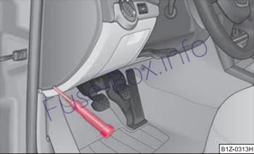
Fuse box location
The fuse box is located on the left side of the dash panel behind the safety cover.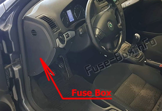
Fuse box diagram
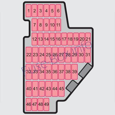
Fuses assignment in the dash panel
| No. | Power consumer | Amperes |
|---|---|---|
| 1 | Diagnostic socket, Engine control unit, Electrical fuel pump | 10 |
| 2 | Control unit for ABS, ESP | 5 |
| 3 | Airbag | 5 |
| 4 | Heating, Air conditioning system, Reversing lights | 5 |
| 5 | Control unit for headlamp beam adjustment | 5 |
| 6 | Instrument cluster, Control unit for automatic gearbox, Control unit for electromechanical power steering, Parking aid; Haldex clutch | 5 |
| 7 | Not assigned | |
| 8 | Not assigned | |
| 9 | Not assigned | |
| 10 | Not assigned | |
| 11 | Not assigned | |
| 12 | Central locking control unit | 10 |
| 13 | Diagnostic socket, Light switch, Brake light | 10 |
| 14 | Control unit for automatic gearbox, Selector lever lock | 5 |
| 15 | Central control unit – interior lights | 5 |
| 16 | Climatronic | 10 |
| 17 | Not assigned | |
| 18 | Not assigned | |
| 19 | Control unit for trailer detection | 5 |
| 20 | Left side cornering lights | 10 |
| 21 | Right side cornering lights | 10 |
| 22 | Air blower for Climatronic | 40 |
| 23 | Front power window | 30 |
| 24 | Cigarette lighter | 25 |
| 25 | Rear window heater | 25 |
| 25 | Rear window heater, Auxiliary heating (auxiliary heating and ventilation) | 30 |
| 26 | Power socket in the luggage compartment | 20 |
| 27 | Fuel pump relay, Injection valves (diesel engine) | 15 |
| 28 | Not assigned | |
| 29 | Engine control unit, Crankcase ventilation heater | 10 |
| 30 | Control unit for automatic gearbox | 20 |
| 31 | Vacuum pump | 20 |
| 32 | Rear power window | 30 |
| 33 | Electric sliding/tilting roof | 25 |
| 34 | Control unit for convenience functions | 20 |
| 35 | Anti-theft alarm system | 5 |
| 36 | Headlight cleaning system | 20 |
| 37 | Front seat heating | 30 |
| 38 | Heated rear seats | 30 |
| 39 | Not assigned | |
| 40 | Air blower for heating and air conditioning | 40 |
| 41 | Rear window wiper | 15 |
| 42 | Not assigned | |
| 43 | Towing device | 15 |
| 44 | Towing device | 20 |
| 45 | Towing device | 15 |
| 46 | Heated windscreen washer nozzles | 3 |
| 47 | Relay for auxiliary heating | 5 |
| 48 | Not assigned | |
| 49 | Light switch | 5 |
Engine Compartment Fuse Box
Engine Compartment Fuse Box
Fuse box location
The fuses are located under the cover in the engine compartment on the left.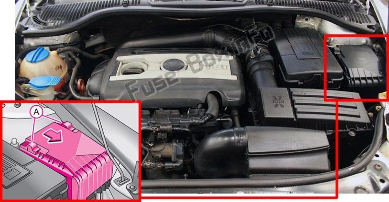
Fuse box diagram (version 1)
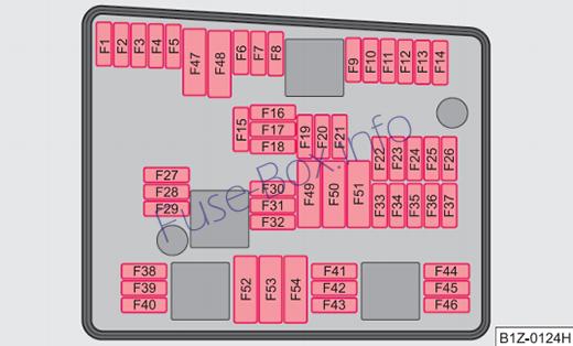
Fuses assignment in engine compartment (version 1)
| No. | Power consumer | Amperes |
|---|---|---|
| F1 | Central control unit, right main headlight, right rear light unit | 30 |
| F2 | Valves for ABS | 20 |
| F3 | Not assigned | |
| F4 | Measuring circuit | 5 |
| F5 | Horn | 15 |
| F6 | Not assigned | |
| F7 | Valve for fuel dosing | 15 |
| F8 | Not assigned | |
| F9 | Activated charcoal filter, exhaust gas recirculation valve | 10 |
| F10 | Leakage diagnosis pump | 10 |
| F11 | Lambda probe upstream of catalytic converter, engine control unit | 10 |
| F12 | Lambda probe downstream of catalytic converter | 10 |
| F13 | Control unit for automatic gearbox | 15 |
| F14 | Not assigned | |
| F15 | Coolant pump | 10 |
| F16 | Not assigned | |
| F17 | Instrument cluster, windshield wiper lever and turn signal light lever | 5 |
| F18 | Audio amplifier (sound system) | 30 |
| F19 | Radio | 15 |
| F20 | Phone | 3 |
| F21 | Not assigned | |
| F22 | Not assigned | |
| F23 | Engine control unit | 10 |
| F24 | Control unit for CAN databus | 5 |
| F25 | Not assigned | |
| F26 | Not assigned | |
| F27 | Not assigned | |
| F28 | Engine control unit | 15 |
| F29 | Actuation for coolant pump after-running | 5 |
| F30 | Control unit for auxiliary heating | 20 |
| F31 | Front window wiper | 30 |
| F32 | Not assigned | |
| F33 | Not assigned | |
| F34 | Not assigned | |
| F35 | Not assigned | |
| F36 | Not assigned | |
| F37 | Not assigned | |
| F38 | Radiator fan, valves | 10 |
| F39 | Clutch pedal switch, brake pedal switch | 5 |
| F40 | Ignition coils | 20 |
| F41 | Not assigned | |
| F42 | Actuation of fuel pump | 5 |
| F43 | Not assigned | |
| F44 | Not assigned | |
| F45 | Not assigned | |
| F46 | Not assigned | |
| F47 | Central control unit, left main headlight, left rear light unit | 30 |
| F48 | Pump for ABS | 40 |
| F49 | Power supply for terminal 15 (ignition on) | 40 |
| F50 | Not assigned | |
| F51 | Not assigned | |
| F52 | Power supply relay – terminal X (In order not to drain the battery unnecessarily when starting the engine, the electrical components of this terminal are automatically switched off) |
40 |
| F53 | Accessory equipment | 50 |
| F54 | Not assigned |
Fuse box diagram (version 2)
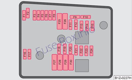
Fuses assignment in engine compartment (version 2)
| No. | Power consumer | Amperes |
|---|---|---|
| F1 | Not assigned | |
| F2 | Control unit for automatic gearbox DQ 200 | 30 |
| F3 | Measuring circuit | 5 |
| F4 | Valves for ABS | 30/20 |
| F5 | Control unit for automatic gearbox | 15 |
| F6 | Instrument cluster, windshield wiper lever and turn signal light lever | 5 |
| F7 | Power suppy terminal 15, Starter | 40 |
| F8 | Radio | 15 |
| F9 | Phone | 5 |
| F10 | Engine control unit, Main relay | 5/10 |
| F11 | Control unit for auxiliary heating | 20 |
| F12 | Control unit for CAN databus | 5 |
| F13 | Engine control unit | 15/30 |
| F14 | Ignition | 20 |
| F15 | Lambda probe, NOx-sensor, Fuel pump relay | 15 |
| F15 | Glow plug system relay | 5 |
| F16 | Central control unit, right main headlight, right rear light unit | 30 |
| F17 | Horn | 15 |
| F18 | Amplifier for digital sound processor | 30 |
| F19 | Front window wiper | 30 |
| F20 | Water pump | 10 |
| F21 | Lambda probe | 10/15 |
| F22 | Clutch pedal switch, brake pedal switch | 5 |
| F23 | Secondary air pump | 5 |
| F23 | Air mass meter | 10 |
| F23 | Fuel high pressure pump | 15 |
| F24 | Activated charcoal filter, exhaust gas recirculation valve | 10 |
| F25 | Pump for ABS | 30/40 |
| F26 | Central control unit, left main headlight, left rear light unit | 30 |
| F27 | Secondary air pump | 40 |
| F27 | Pre-glowing | 50 |
| F28 | Not assigned | |
| F29 | Power supply terminal 30 | 50 |
| F30 | Terminal X (In order not to drain the battery unnecessarily when starting the engine, the electrical components of this terminal are automatically switched off) |
40 |


