
See other Ford Transit Connect:
Fuse Layout Ford Transit Connect 2010-2013
Contents
![]()
![]()
Cigar lighter (power outlet) fuses in the Ford Transit Connect are the fuses #143 (Cigar lighter, Front power point), #169 (Second power point) and #174 (Rear power point / Rear center console power point) in the Instrument panel fuse box.
Table of Contents
Fuse box location
Passenger compartment
The fuse panel and relay box are located below the instrument panel to the left of the steering wheel, behind the cover to the left of the steering wheel.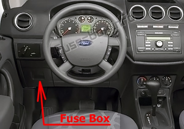
Engine compartment
The power distribution box is located in the engine compartment.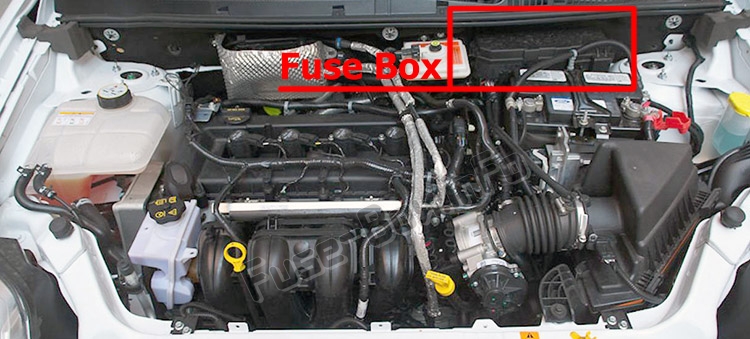
Fuse box diagrams
2010
Passenger compartment
Assignment of the fuses in the Passenger compartment (2010)
| № | Amp rating | Protected Circuits |
|---|---|---|
| 120 | — | Headlamps, Low beam interrupt relay |
| 121 | — | Not used |
| 122 | — | Rear window defroster relay |
| 123 | — | Heater blower relay |
| 124 | — | Interior lamps relay |
| 125 | — | Windshield wipers relay |
| 126 | — | Rear unlock relay |
| 130 | 15A | Hazard flashers |
| 131 | 5A | Power mirrors |
| 132 | 10A | Light switch, Exterior lighting |
| 133 | — | Not used |
| 134 | — | Not used |
| 135 | — | Not used |
| 136 | 15A | Horn |
| 137 | 7.5A | Tire pressure monitoring system (TPMS), Radio, Instrument cluster |
| 138 | — | Not used |
| 139 | — | Not used |
| 140 | — | Not used |
| 141 | 10A | Rear fog lamps |
| 142 | 15A | Brake lamps |
| 143 | 15A | Cigar lighter, Front power point |
| 144 | — | Not used |
| 145 | — | Not used |
| 146 | 20A | Windshield wipers, Wiper switch |
| 147 | — | Not used |
| 148 | 7.5A | Recirculation, Instrument cluster |
| 149 | — | Not used |
| 150 | — | Not used |
| 151 | 15A | Radio, Bluetooth®/Voice command module |
| 152 | 7.5A | A/ C switch, Park aid module |
| 153 | 7.5A | Interior lamps, Battery saver |
| 154 | — | Not used |
| 155 | — | Not used |
| 156 | 7.5A | Right parking lamp/tail lamps |
| 157 | 7.5A | License plate lamps |
| 158 | 10A | Light switch |
| 159 | — | Not used |
| 160 | — | Not used |
| 161 | 7.5A | Anti-lock brake system (ABS)/Traction control, Steering angle sensor |
| 162 | 7.5A | Airbag module, Passenger airbag off indicator |
| 163 | 20A | Locks |
| 164 | — | Not used |
| 165 | — | Not used |
| 166 | 25A | Front power windows |
| 167 | 7.5A | Rear window defroster/heated mirror switch |
| 168 | — | Not used |
| 169 | 15A | Second power point |
| 170 | — | Not used |
| 171 | — | Not used |
| 172 | — | Not used |
| 173 | — | Not used |
| 174 | 15A | Rear power point |
| 175 | 7.5A | Left park lamps/tail lamps |
| 176 | — | Not used |
| 177 | — | Not used |
| 178 | 25A | Rear window defroster |
| 179 | 7.5A | Instrument cluster, Passive anti-theft system (PATS), Accelerator pedal sensor, TPMS |
| 180 | 20A | Front and rear window washer |
| 181 | — | Not used |
| 182 | — | Not used |
Engine compartment
Assignment of the fuses in the Power distribution box (2010)
| № | Amp rating | Protected circuits |
|---|---|---|
| 1 | — | Not used |
| 2 | 40A** | Passenger compartment fuse panel |
| 3 | 20A** | Ignition switch |
| 4 | 20A** | Fuel pump |
| 5 | 10 A* | Powertrain control module (PCM) keep alive power, Canister solenoid |
| 6 | 15 A* | PCM, Data link connector |
| 7 | 10 A* | Backup lamps |
| 8 | 15 A* | Headlamps |
| 9 | 40A** | Passenger compartment fuse panel II |
| 10 | 30A** | Passenger compartment fuse panel III |
| 11 | 30A** | Start lock |
| 12 | 30A** | Anti-lock brake system (ABS) pump motor |
| 13 | 30A* | Heater blower motor |
| 14 | 10 A* | PCM relay |
| 15 | 20A** | ABS/Traction control valves |
| 16 | 30 A** | Cooling fan – low |
| 17 | 50A** | Cooling fan – high |
| 18 | 20A** | Daytime running lamps (DRL), Low beam interrupt relay |
| 19 | 20A** | Tire pressure monitoring system |
| 20 | — | A/C clutch relay |
| 21A | — | Ignition overload relay |
| 21B | — | Not used |
| 21C | — | High beam headlamp relay |
| 21D | — | PCM relay |
| 22 | 10 A* | PCM, Auxiliary connector, Fuel injectors |
| 23 | 10 A* | Right low beam headlamp |
| 24 | 10 A* | A/C clutch solenoid |
| 25 | 10 A* | Left low beam headlamp |
| 26 | 10 A* | Mass air flow sensor, Brake switch, Backup lamps relay, EGR stepper motor, EVAP canister purge valve, Heated oxygen sensors, Floor shifter, Transmission range sensor |
| 27 | — | Not used |
| 28 | 15 A* | PCM vehicle power 1 |
| 29 | 15 A* | Auxiliary connector, Coil on plugs |
| 30A, 30B | 70A Relay | Cooling fan high relay |
| 30C | — | Cooling fan low relay |
| 30D | — | Start lock relay |
| 31A | — | Backup lamp relay |
| 31B | — | Fuel pump relay |
| 31C | — | DRL relay |
| 31D | — | Low beam headlamps relay |
| 31E | — | Not used |
| 31F | — | Not used |
| 32 | — | Cooling fan diode |
| 33 | — | Fuel pump relay diode |
| 34 | — | Gear shifter diode |
| 35 | 10 A* | PCM ignition |
| 36 | — | Not used |
| * Mini fuse ** Cartridge fuse |
2011, 2012, 2013
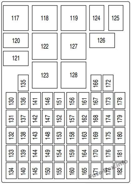
Passenger compartment
Assignment of the fuses in the Passenger compartment (2011, 2012, 2013)
| № | Amp rating | Protected circuits |
|---|---|---|
| 117 | — | Not used |
| 118 | — | Not used |
| 119 | — | Not used |
| 120 | — | Headlamps, Low beam interrupt relay |
| 121 | — | Front fog lamp interrupt relay |
| 122 | — | Rear window defroster relay |
| 123 | — | Heater blower relay |
| 124 | — | Interior lamps relay |
| 125 | — | Windshield wipers relay |
| 126 | — | Rear unlock relay |
| 127 | — | Ignition overload relay |
| 128 | — | Battery saver relay (modified vehicle) |
| 130 | 15A | Hazard flashers |
| 131 | 5A | Power mirrors |
| 132 | 10A | Light switch, Exterior lighting |
| 133 | — | Not used |
| 134 | — | Not used |
| 135 | — | Not used |
| 136 | 15A | Horn |
| 137 | 7.5A | Tire pressure monitoring system, Radio, Instrument cluster |
| 138 | 10A | Reverse lamp |
| 139 | 20A | Ignition supply (modified vehicle) |
| 140 | — | Not used |
| 141 | 7.5A | Front/rear fog lamps |
| 142 | 15A | Brake lamps |
| 143 | 20A | Cigar lighter, Front power point |
| 144 | 10A | Ignition supply (modified vehicle} |
| 145 | — | Not used |
| 146 | 20A | Windshield wipers, Wiper switch |
| 147 | 15A | Front fog lamps |
| 148 | 7.5A | Recirculation, Instrument cluster |
| 149 | 10A | Ignition supply/Battery supply (modified vehicle) |
| 150 | — | Not used |
| 151 | 15A | Radio, Bluetooth/Voice command module |
| 152 | 7.5A | A/C switch, Park aid module |
| 153 | 7.5A | Interior lamps, Battery saver |
| 154 | 15A | Roof lamp (modified vehicle) |
| 155 | 10A | Battery saver (modified vehicle) |
| 156 | 7.5A | Right parking lamp/tail lamps |
| 157 | 7.5A | License plate lamps |
| 158 | 10A | Light swatch |
| 159 | 20A | Rear heater blower fan (modified vehicle) |
| 160 | — | Not used |
| 161 | 7.5A | Anti-lock brake system/Roll stability control, Steering angle sensor |
| 162 | 7.5A | Airbag module, Passenger airbag off indicator |
| 163 | 20A | Locks |
| 164 | 20A | Tire pressure monitoring system module |
| 165 | — | Not used |
| 166 | 25A | Front power windows |
| 167 | 7.5A | Rear window defroster/heated mirror swatch |
| 168 | — | Not used |
| 169 | 20A | Second power point |
| 170 | — | Not used |
| 171 | — | Not used |
| 172 | 10A | Right rear turn signal (modified vehicle) |
| 173 | 10A | Left rear turn signal (modified vehicle) |
| 174 | 20A | Rear power point, Rear center console power point (modified vehicle) |
| 175 | 7.5A | Left park lamps/tail lamps |
| 176 | — | Not used |
| 177 | — | Not used |
| 178 | 25A | Rear window defroster |
| 179 | 7.5A | Instrument cluster, Passive anti-theft system, Accelerator pedal sensor, Tire pressure monitoring system, Rearview camera |
| 180 | 20A | Front and rear window washer |
| 181 | — | Not used |
| 182 | — | Not used |
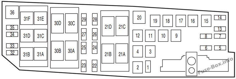
Engine compartment
Assignment of the fuses in the Power distribution box (2011, 2012, 2013)
| № | Amp rating | Protected circuits |
|---|---|---|
| 1 | 7.5 A* | Heated windshield telltale |
| 2 | 40A** | Right heated windshield, Modified vehicle – Rear heater blower fan, Ignition supply |
| 3 | 50A** | Left heated windshield, Modified vehicle – Batteiy supply |
| 4 | 20A** | Fuel pump |
| 5 | 10 A* | Powertrain control module keep alive power, Canister solenoid |
| 6 | 15 A* | Powertrain control module, Data link connector |
| 7 | 20A* | Ignition switch |
| 8 | 15 A* | Headlamps |
| 9 | 40A** | Passenger compartment fuse panel II |
| 10 | 25A** | Modified vehicle – Rear turn signal, Battery supply |
| 11 | 40A** | Ignition overload, Passenger compartment fuse panel |
| 12 | 30A** | Anti-lock brake system / Roll stability control pump motor |
| 13 | 30A* | Heater blower motor |
| 14 | 10 A* | Powertrain control module relay |
| 15 | 20A** | Anti-lock brake system / Roll stability control valves |
| 16 | 30A** | Cooling fan – low |
| 17 | 50A** | Cooling fan – high |
| 18 | 25A** | Daytime running lamps, Low beam interrupt relay |
| 19 | 50A** | Passenger compartment fuse panel III |
| 20 | — | A/C clutch relay |
| 21A | — | Right heated windshield relay, Modified vehicle – Rear fan relay |
| 21B | — | Starter lock relay |
| 21C | — | High beam headlamp relay |
| 21D | — | Powertrain control module relay |
| 22 | 10 A* | Powertrain control module, Auxiliary connector, Fuel injectors |
| 23 | 10 A* | Right low beam headlamp |
| 24 | 10 A* | A/C clutch solenoid |
| 25 | 10 A* | Left low beam headlamp |
| 26 | 10 A* | Mass air flow sensor, Brake switch, Backup lamps relay, Exhaust gas recovery valve stepper motor, Electronic vapor canister purge valve, Heated oxygen sensors, Floor shifter, Transmission range sensor |
| 27 | — | Not used |
| 28 | 15 A* | Powertrain control module vehicle power 1 |
| 29 | 15 A* | Auxiliary connector, Coil on plugs |
| 30A, 30B | 70A Relay | Cooling fan high relay |
| 30C | — | Cooling fan low relay |
| 30D | — | Left heated windshield relay |
| 31A | — | Backup lamp relay |
| 31B | — | Fuel pump relay |
| 31C | — | Daytime running lamps relay |
| 31D | — | Low beam headlamps relay |
| 31E | — | Modified vehicle – Right rear turn signal relay |
| 31F | — | Front fog lamps |
| 32 | — | Cooling fan diode |
| 33 | — | Fuel pump relay diode |
| 34 | — | Gear shifter diode |
| 35 | 30A* | Start lock relay |
| 36 | — | Modified vehicle – Left rear turn signal relay |
| * Mini fuse ** Cartridge fuse |


