

See other Ford Ranger:


Table of Contents
Fuse Layout Ford Ranger 2019-…
Contents

Cigar lighter (power outlet) fuses in the Ford Ranger are the fuses #5 (Auxiliary power point 3 – console rear), #10 (Auxiliary power point 1 – instrument panel), #16 (Auxiliary power point 2 – instrument panel) and # 17 (Auxiliary power point – rear cargo area) in the Engine compartment fuse box.
Fuse box location
Passenger compartment
The fuse panel is located below and outboard of the steering column behind the access cover.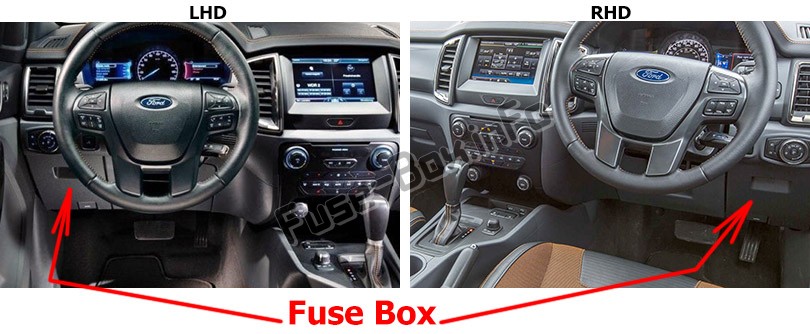
Engine compartment
The power distribution box is located in the engine compartment (left-side).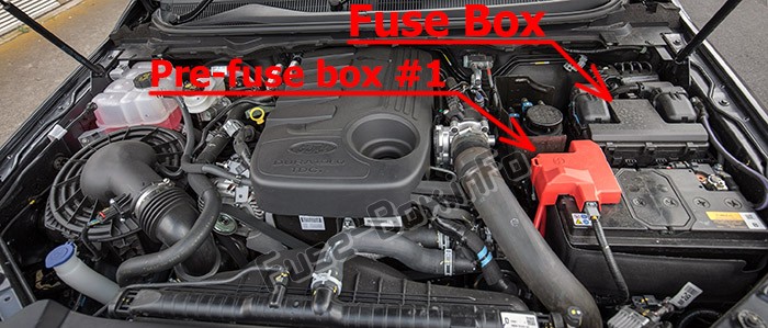
Power Distribution Box – Bottom
There are fuses located on the bottom of the fuse box.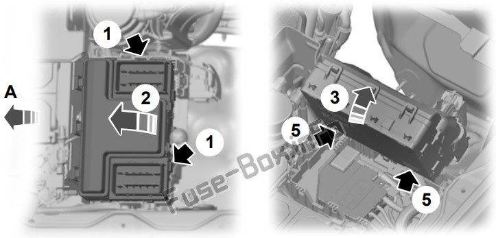
To access, do the following:
1. Release the two latches, located on both sides of the fusebox;
2. Raise the rear side of the fusebox from the cradle;
3. Move the fusebox toward the rear side of the engine compartment and rotate as shown;
4. Pivot the rear side of the fusebox to access the bottom side;
5. Release the two latches to open the cover.
Pre-fuse Box #1
It is attached to the positive battery terminal.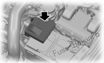
Pre-fuse Box #2
It is located below the engine compartment fuse box.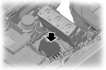
Fuse box diagrams
2019
Passenger compartment
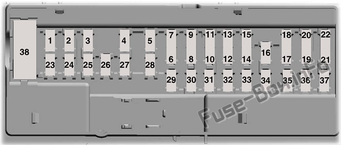
Assignment of the fuses in the Passenger compartment (2019)
| № | Amp Rating | Protected Component |
|---|---|---|
| 1 | – | Not used |
| 2 | 7.5A | Not used (spare) |
| 3 | 20A | Driver door lock |
| 4 | 5A | Not used (spare) |
| 5 | 20A | Branded audio amplifier |
| 6 | 10A | Not used (spare) |
| 7 | 10A | Not used (spare) |
| 8 | 10A | Security horn |
| 9 | 10A | Telematics |
| 10 | 5A | Not used (spare) |
| 11 | 5A | Not used (spare) |
| 12 | 7.5A | Electronic control panel Climate control |
| 13 | 7.5A | Instrument cluster Steering column control module Data link connector |
| 14 | 10A | Extended power module (for Restraints module and Occupant module) |
| 15 | 10A | Gateway module Data link connector |
| 16 | 15 A | Rear doors double lock |
| 17 | 5A | Not used (spare) |
| 18 | 5A | Ignition switch Lock solenoid Push button start |
| 19 | 7.5A | Extended power module (for Restraints module and Occupant module) |
| 20 | 7.5A | Not used (spare) |
| 21 | 5A | Humidity and in-car temperature sensor |
| 22 | 5A | Not used (spare) |
| 23 | 10A | Inverter Door lock switch |
| 24 | 20A | Central locking system |
| 25 | 30A | Driver door power window |
| 26 | 30A | Not used (spare) |
| 27 | 30A | Not used (spare) |
| 28 | 20A | Branded audio amplifier |
| 29 | 30A | Not used (spare) |
| 30 | 30A | Not used (spare) |
| 31 | 15A | Not used (spare) |
| 32 | 10A | Radio transceiver module Door entry remote SYNC |
| 33 | 20A | Audio unit |
| 34 | 30A | Run/start relay |
| 35 | 5A | Not used (spare) |
| 36 | 15A | Auto-dimming interior mirror Mirror adjustment control |
| 37 | 20A | Not used (spare) |
| 38 | 30A | Power windows |
Engine compartment
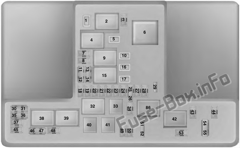
Assignment of the fuses and relays in the Power distribution box (2019)
| № | Amp Rating | Protected Component |
|---|---|---|
| 1 | 15 A | Not used |
| 2 | – | Starter motor solenoid relay |
| 3 | 5A | Rain sensor |
| 4 | – | Blower motor relay |
| 5 | 20A | Auxiliary power point 3 – console rear |
| 6 | – | Trailer park lamp relay |
| 7 | 20A | Powertrain control module |
| 8 | 20A | Cannister vent solenoid Fuel vapor shutoff valve Canister purge valve Variable cam timing valve 1 and 2 Heated oxygen sensors |
| 9 | – | Powertrain control module relay |
| 10 | 20A | Auxiliary power point 1 – instrument panel |
| 11 | 15 A | Ignition coils |
| 12 | 15 A | A/C control drive Transaxle warmer Auxiliary water pump Aspirator valve control Fan clutch Oil pump Turbo bypass |
| 13 | 15 A | Not used (spare) |
| 14 | 15 A | Not used (spare) |
| 15 | – | Run/start relay |
| 16 | 20A | Auxiliary power point 2 – instrument panel |
| 17 | 20A | Auxiliary power point – rear cargo area |
| 18 | 10 A | Not used (spare) |
| 19 | 10 A | Electric power assist steering |
| 20 | 10 A | Lighting control switch |
| 21 | 5A | Transmission Run/Start relay |
| 22 | 10 A | Air conditioning compressor |
| 23 | 7.5A | Voltage quality module |
| 24 | 10 A | Not used (spare) |
| 25 | 10 A | Anti-lock brake system |
| 26 | 10 A | Not used (spare) |
| 27 | – | Not used |
| 28 | 10 A | Powertrain control module |
| 29 | 7.5 A | USB charge port |
| 30 | – | Not used |
| 31 | – | Not used |
| 32 | – | Fuel pump relay |
| 33 | – | A/C clutch relay |
| 34 | 10 A | Trailer reverse lamp |
| 35 | 15A | Not used (spare) |
| 36 | – | Not used |
| 37 | 10 A | Heated exterior mirror |
| 38 | – | Trailer right turn and stop lamp relay |
| 39 | – | Trailer left turn and stop lamp relay |
| 40 | – | Trailer reverse lamp relay |
| 41 | – | Horn relay |
| 42 | – | 4WD (four-wheel drive) motor no 2 relay |
| 43 | – | Not used |
| 44 | – | Not used |
| 45 | 5A | Not used (spare) |
| 46 | 10 A | Not used (spare) |
| 47 | 10 A | Brake pedal switch |
| 48 | 20A | Horn |
| 49 | 15 A | Transmission control module Oil pump |
| 50 | 10 A | Wiper park heater |
| 51 | – | Not used |
| 52 | – | Not used |
| 53 | 15 A | Rear differential lock |
| 54 | – | Not used |
| 55 | – | Not used |
| 86 | – | 4WD motor no 1 relay |
Engine compartment, Bottom
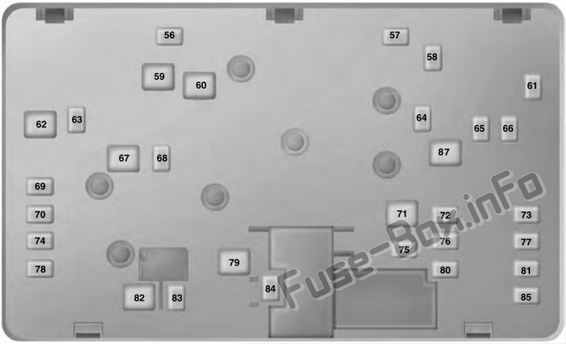
Assignment of the fuses and relays in the Power distribution box (Bottom) (2019)
| № | Amp Rating | Protected Component |
|---|---|---|
| 56 | 15A | Trailer left turn and stop |
| 57 | – | Not used |
| 58 | – | Not used |
| 59 | – | Not used |
| 60 | 30A | Fuel pump control module |
| 61 | – | Not used |
| 62 | 50A | Body control module 1 – lighting |
| 63 | 15A | Trailer right turn and stop |
| 64 | 30A | Trailer brakes |
| 65 | 20A | Heated driver seat |
| 66 | 25A | Four wheel drive |
| 67 | 50A | Body control module 2 – lighting |
| 68 | 30A | Rear window defroster |
| 69 | 30A | Anti-lock brake system valves |
| 70 | 30A | Passenger power seat |
| 71 | 30A | Trailer park lamps |
| 72 | – | Not used |
| 73 | 30A | Trailer module |
| 74 | 30A | Driver power seat |
| 75 | – | Not used |
| 76 | – | Not used |
| 77 | – | Not used |
| 78 | – | Not used |
| 79 | 40A | Blower motor |
| 80 | 20A | Heated passenger seat |
| 81 | 40A | Inverter |
| 82 | 60A | Anti-lock brake system pump |
| 83 | 30A | Windshield wiper motor |
| 84 | 30A | Starter motor solenoid |
| 85 | – | Not used |
| 87 | 40A | Trailer module |
Pre-fuse Box #1 (on the battery)
| № | Amp Rating | Protected Component |
|---|---|---|
| 1 | 225A | Alternator |
| 2 | 125A | Electronic power assist steering |
Pre-fuse Box #2 (below the fuse box)
| № | Amp Rating | Protected Component |
|---|---|---|
| 1 | – | Not used |
| 2 | 125A | Body control module |
| 3 | 50A | Voltage quality module (supplies rear lamp blind spot, rear view camera, head up display, 4×4 switch, image processing module and adaptive cruise control radar) |
| 4 | – | Busbar through to power distribution box |


