


Fuse Layout Ford Mustang 2005-2009
Contents

Cigar lighter (power outlet) fuses in the Ford Mustang are the fuses #61 (Power point #1 (Instrument panel)) and #64 (Power point #2 (Console)) in the Engine compartment fuse box.
Table of Contents
Fuse box location
Passenger compartment
The fuse panel is located in the lower passenger side area behind the kick panel.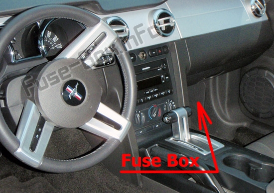
Engine compartment
The power distribution box is located in the engine compartment.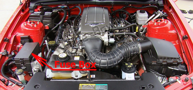
Auxiliary relay (if equipped)
There is a relay located on the accelerator pedal assembly for the PCM delay.
Note: Only on manual transmission applications.
Auxiliary relay with heated seats (if equipped)
On heated seat equipped vehicles, there is a relay box located behind the headlamp switch area containing two micro relays for the driver and passenger heated seats.
Auxiliary relay with HID headlamps (if equipped)
On vehicles equipped with HID headlamps, an auxiliary relay box is located under the hood on the right-hand side front of the engine compartment. This auxiliary relay box contains the left front and right front HID headlamp relays.
Fuse box diagrams
2005
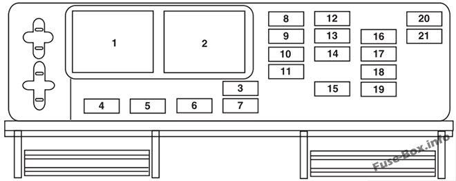
Passenger compartment
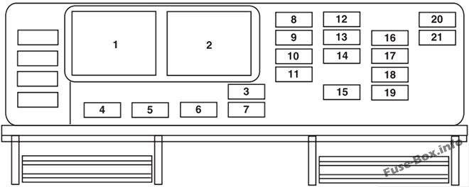
Assignment of the fuses in the Passenger compartment (2005)
| № | Amp Rating | Description |
|---|---|---|
| 1 | Mini relay | Accessory delay #1 |
| 2 | — | Not used |
| 3 | 10A | Wiper power |
| 4 | 5A | Power mirrors |
| 5 | — | Not used |
| 6 | 5A | Accessory delay feeds |
| 7 | 5A | Overdrive cancel |
| 8 | 10A | Cluster, Data Link Connector (DLC) |
| 9 | — | Not used |
| 10 | 5A | Intrusion Sensing Module (ISM), Climate control |
| 11 | — | Not used |
| 12 | 5A | Climate control, Ignition |
| 13 | — | Not used |
| 14 | 5A | A/C cycle switch |
| 15 | 10A | Brake On/Off (BOO) power |
| 16 | 5A | Cluster |
| 17 | 10A | Restraint Control Module (RCM), Passenger Occupant Detection System (PODS), Passenger Air bag Deactivation Indicator (PADI) |
| 18 | 10A | Anti-lock Brake System (ABS), Positive Crankcase Ventilation (PCV) valve heater, Ignition |
| 19 | 5A | Powertrain Control Module (PCM) relays, Passive Anti-Theft System (PATS) |
| 20 | 10A | Radio (Start) |
| 21 | 10A | Starter relay |
Engine compartment
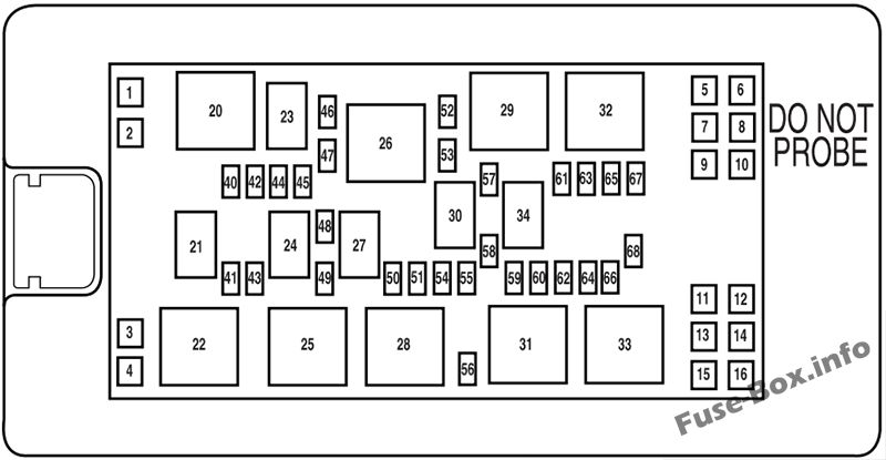
Assignment of the fuses in the Power distribution box (2005)
| № | Amp Rating | Description |
|---|---|---|
| 1 | — | Not used |
| 2 | 30A* | Climate control blower |
| 3 | 40A* | Cooling fan |
| 4 | 30A* | Starter |
| 5 | 30A* | Right front window motor |
| 6 | 30A* | Rear amplifier (Shaker 1000 radio) |
| 7 | 30A* | Left front window motor |
| 8 | 40A* | Anti-lock Brake System (ABS) #1 |
| 9 | 30A* | Rear amplifier (Shaker 1000 radio) |
| 10 | 30A* | Wipers |
| 11 | 30A* | Left rear window motor (Convertible only) |
| 12 | 30A* | Right rear window motor (Convertible only) |
| 13 | 30A* | Convertible top |
| 14 | 30A* | Seat |
| 15 | — | Not used |
| 16 | 30A* | Front amplifier (Shaker 500 radio) |
| 20 | Mini relay | PCM #2 |
| 21 | Micro relay | Fuel pump |
| 22 | Mini relay | Starter |
| 23 | Micro relay | PCM #1 |
| 24 | Micro relay | A/C clutch |
| 25 | Mini relay | Cooling fan (High-speed) |
| 26 | Mini relay | Horn |
| 27 | Micro relay | High beams |
| 28 | Mini relay | Cooling fan (Low-speed) |
| 29 | Mini relay | Rear defroster |
| 30 | Micro relay | Fog lamps |
| 31 | Mini relay | Convertible top (Up) |
| 32 | Mini relay | Climate control blower |
| 33 | Mini relay | Convertible top (Down) |
| 34 | — | Not used |
| 35 | — | Not used |
| 36 | — | Not used |
| 37 | — | Not used |
| 38 | — | Not used |
| 39 | — | Not used |
| 40 | 15 A** | Engine #2 |
| 41 | 15 A** | Fuel pump |
| 42 | 15 A** | Engine #3 |
| 43 | 10A** | Alternator |
| 44 | 10A** | Delayed accessory |
| 45 | 10A** | PCM |
| 46 | 25A** | Horn |
| 47 | 15 A** | Engine #1 |
| 48 | Diode | A/C clutch |
| 49 | 15 A** | A/C clutch |
| 50 | 15A** | High beams |
| 51 | 10A** | Convertible top |
| 52 | 30A** | Rear defroster |
| 53 | Diode | PCM |
| 54 | 10A** | PCM delay |
| 55 | — | Not used |
| 56 | 20A** | Radio |
| 57 | 20A** | Decklid release |
| 58 | 15A** | Fog lamps |
| 59 | 30A** | SJB #5 (Instrument panel fuse box) |
| 60 | — | Not used |
| 61 | 20A** | Power point #1 (Instrument panel) |
| 62 | 20A** | SJB #7 (Instrument panel fuse box) |
| 63 | 30A** | SJB #6 (Instrument panel fuse box) |
| 64 | 20A** | Power point #2 (Console) |
| 65 | 30A** | ABS #2 |
| 66 | — | Not used |
| 67 | 30A** | SJB #4 (Instrument panel fuse box) |
| 68 | 20A** | Ignition |
| * Cartridge Fuses ** Mini Fuses |
2006
Passenger compartment
Assignment of the fuses in the Passenger compartment (2006)
| № | Amp Rating | Description |
|---|---|---|
| 1 | Mini relay | Accessory delay #1 |
| 2 | — | Not used |
| 3 | 10A | Wiper power |
| 4 | 5A | Power mirrors |
| 5 | — | Not used |
| 6 | 5A | Accessory delay feeds |
| 7 | 10A | Overdrive cancel |
| 8 | 10A | Cluster, Data Link Connector (DLC) |
| 9 | — | Not used |
| 10 | 5A | Intrusion Sensing Module (ISM), Climate control |
| 11 | — | Not used |
| 12 | 5A | Climate control, Ignition |
| 13 | — | Not used |
| 14 | 5A | A/C cycle switch |
| 15 | 10A | Brake On/Off (BOO) power |
| 16 | 5A | Cluster |
| 17 | 10A | Restraint Control Module (RCM), Passenger Occupant Detection System (PODS), Passenger Air bag Deactivation Indicator (PADI) |
| 18 | 10A | Anti-lock Brake System (ABS), Positive Crankcase Ventilation (PCV) valve heater, Ignition |
| 19 | 5A | Powertrain Control Module (PCM) relays, Passive Anti-Theft System (PATS) |
| 20 | 10A | Radio (Start) |
| 21 | 10A | Starter relay |
Engine compartment
Assignment of the fuses in the Power distribution box (2006)
| № | Amp Rating | Description |
|---|---|---|
| 1 | — | Not used |
| 2 | 30A* | Climate control blower |
| 3 | 40A* | Cooling fan |
| 4 | 30A* | Starter |
| 5 | 30A* | Driver front window motor |
| 6 | 30A* | Rear amplifier (Shaker 1000 radio) |
| 7 | 30A* | Passenger front window motor |
| 8 | 40A* | Anti-lock Brake System (ABS) #1 |
| 9 | 30A* | Rear amplifier (Shaker 1000 radio) |
| 10 | 30A* | Wipers |
| 11 | 30A* | Driver rear window motor (Convertible only) |
| 12 | 30A* | Passenger rear window motor (Convertible only) |
| 13 | 40A* | Convertible top |
| 14 | 30A* | Seat |
| 15 | — | Not used |
| 16 | 30A* | Front amplifier (Shaker 500 radio) |
| 20 | Mini relay | PCM #2 |
| 21 | Micro relay | Fuel pump |
| 22 | Mini relay | Starter |
| 23 | Micro relay | PCM #1 |
| 24 | Micro relay | A/C clutch |
| 25 | Mini relay | Cooling fan (High-speed) |
| 26 | Mini relay | Horn |
| 27 | Micro relay | High beams |
| 28 | Mini relay | Cooling fan (Low-speed) |
| 29 | Mini relay | Rear defroster |
| 30 | Micro relay | Fog lamps |
| 31 | Mini relay | Convertible top (Up) |
| 32 | Mini relay | Climate control blower |
| 33 | Mini relay | Convertible top (Down) |
| 34 | Micro relay | Decklid |
| 35 | — | Not used |
| 36 | — | Not used |
| 37 | — | Not used |
| 38 | — | Not used |
| 39 | — | Not used |
| 40 | 15 A** | Engine #2 |
| 41 | 15 A** | Fuel pump |
| 42 | 15 A** | Engine #3 |
| 43 | 10A** | Alternator |
| 44 | 10A** | Delayed accessory |
| 45 | 10A** | PCM |
| 46 | 25A** | Horn |
| 47 | 15 A** | Engine #1 |
| 48 | Diode | A/C clutch |
| 49 | 15 A** | A/C clutch |
| 50 | 15A** | High beams |
| 51 | 10A** | Convertible top |
| 52 | 30A** | Rear defroster |
| 53 | Diode | PCM |
| 54 | 10A** | PCM delay |
| 55 | — | Not used |
| 56 | 20A** | Radio |
| 57 | 20A** | Decklid release |
| 58 | 15A** | Fog lamps |
| 59 | 30A** | SJB #5 (Instrument panel fuse box) |
| 60 | — | Not used |
| 61 | 20A** | Power point #1 (Instrument panel) |
| 62 | 20A** | SJB #7 (Instrument panel fuse box) |
| 63 | 30A** | SJB #6 (Instrument panel fuse box) |
| 64 | 20A** | Power point #2 (Console) |
| 65 | 30A** | ABS #2 |
| 66 | — | Not used |
| 67 | 30A** | SJB #4 (Instrument panel fuse box) |
| 68 | 20A** | Ignition |
| * Cartridge Fuses ** Mini Fuses |
2007
Passenger compartment
Assignment of the fuses in the Passenger compartment (2007)
| № | Amp Rating | Description |
|---|---|---|
| 1 | Mini relay | Accessory delay #1 |
| 2 | — | Not used |
| 3 | 10A | Wiper power/Blower motor relay |
| 4 | 5A | Power mirrors |
| 5 | — | Not used |
| 6 | 5A | Accessory delay feeds |
| 7 | 10A | Electrochromic mirror |
| 8 | 10A | Cluster, Data Link Connector (DLC) |
| 9 | — | Not used |
| 10 | 5A | Intrusion Sensing Module (ISM), Climate control |
| 11 | — | Not used |
| 12 | 5A | Climate control, Ignition |
| 13 | — | Not used |
| 14 | 5A | A/C cycle switch |
| 15 | 10A | Brake On/Off (BOO) power |
| 16 | 5A | Cluster |
| 17 | 10A | Restraint Control Module (RCM), Passenger Occupant Detection System (PODS), Passenger Air bag Deactivation Indicator (PADI) |
| 18 | 10A | Anti-lock Brake System (ABS) |
| 19 | 5A | Powertrain Control Module (PCM) relay, Passive Anti-Theft System (PATS), Instrument cluster airbag warning lamp |
| 20 | 10A | Radio (Start) |
| 21 | 10A | Starter relay |
Engine compartment
Assignment of the fuses in the Power distribution box (2007)
| № | Amp Rating | Description |
|---|---|---|
| 1 | — | Not used |
| 2 | 30A* | Climate control blower |
| 3 | 40A* | Cooling fan |
| 4 | 30A* | Starter |
| 5 | 30A* | Driver front window motor |
| 6 | 30A* | Rear amplifier (Shaker 1000 radio) |
| 7 | 30A* | Passenger front window motor |
| 8 | 40A* | Anti-lock Brake System (ABS) #1 |
| 9 | 30A* | Rear amplifier (Shaker 1000 radio) |
| 10 | 30A* | Wipers |
| 11 | 30A* | Driver rear window motor (Convertible only) |
| 12 | 30A* | Passenger rear window motor (Convertible only) |
| 13 | 40A* | Convertible top |
| 14 | 30A* | Driver seat |
| 15 | 30A* | Passenger seat |
| 16 | 30A* | Front amplifier (Shaker 500 radio) |
| 20 | Mini relay | PCM |
| 21 | Micro relay | Fuel pump |
| 22 | Mini relay | Starter |
| 23 | — | Not used |
| 24 | Micro relay | A/C clutch |
| 25 | Mini relay | Cooling fan (High-speed) |
| 26 | Mini relay | Horn |
| 27 | Micro relay | High beams |
| 28 | Mini relay | Cooling fan (Low-speed) |
| 29 | Mini relay | Rear defroster |
| 30 | Micro relay | Fog lamps |
| 31 | Mini relay | Convertible top (Up) |
| 32 | Mini relay | Climate control blower |
| 33 | Mini relay | Convertible top (Down) |
| 34 | Micro relay | Decklid |
| 39 | 15A** | Engine #4 |
| 40 | 15A** | Engine #2 |
| 41 | 15 A** | Fuel pump |
| 42 | 15 A** | Engine #3 |
| 43 | 10A** | Alternator |
| 44 | 10A** | Delayed accessory |
| 45 | 10A** | PCM |
| 46 | 25A** | Horn |
| 47 | 15 A** | Engine #1 |
| 48 | Diode | A/C clutch |
| 49 | 15 A** | A/C clutch |
| 50 | 15A** | High beams |
| 51 | 10A** | Convertible top |
| 52 | 30A** | Rear defroster |
| 53 | Diode | PCM |
| 54 | — | Not used |
| 55 | — | Not used |
| 56 | 20A** | Radio, SDARS |
| 57 | 20A** | Decklid release |
| 58 | 15A** | Fog lamps |
| 59 | 30A** | SJB #5 (Passenger compartment fuse box) |
| 60 | — | Not used |
| 61 | 20A** | Power point #1 (Instrument panel) |
| 62 | 20A** | SJB #7 (Passenger compartment fuse box) |
| 63 | 30A** | SJB #6 (Passenger compartment fuse box) |
| 64 | 20A** | Power point #2 (Console) |
| 65 | 30A** | ABS #2 |
| 66 | 25A** | Heated seats |
| 67 | 30A** | SJB #4 (Passenger compartment fuse box) |
| 68 | 20A** | Ignition |
| * Cartridge Fuses ** Mini Fuses |
2008
Passenger compartment
Assignment of the fuses in the Passenger compartment (2008)
| № | Amp Rating | Description |
|---|---|---|
| 1 | Mini relay | Accessory delay #1 |
| 2 | — | Not used |
| 3 | 10A | Wiper power/Blower motor relay |
| 4 | 5A | Power mirrors |
| 5 | — | Not used |
| 6 | 5A | Accessory delay feeds |
| 7 | 10A | Electrochromic mirror/ Ambient lighting |
| 8 | 10A | Cluster, Data Link Connector (DLC) |
| 9 | — | Not used |
| 10 | 5A | Intrusion Sensing Module (ISM), Climate control |
| 11 | — | Not used |
| 12 | 5A | Climate control, Ignition |
| 13 | — | Not used |
| 14 | 5A | A/C cycle switch |
| 15 | 10A | Brake On/Off (BOO) power |
| 16 | 5A | Cluster |
| 17 | 10A | Restraint Control Module (RCM), Passenger Occupant Detection System (PODS), Passenger Air bag Deactivation Indicator (PADI) |
| 18 | 10A | Anti-lock Brake System (ABS) |
| 19 | 5A | Powertrain Control Module (PCM) relay, Passive Anti-Theft System (PATS), Instrument cluster airbag warning lamp |
| 20 | 10A | Radio (Start) |
| 21 | 10A | Starter relay |
Engine compartment
Assignment of the fuses in the Power distribution box (2008)
| № | Amp Rating | Description |
|---|---|---|
| 1 | — | Not used |
| 2 | 30A* | Climate control blower |
| 3 | 40A* | Cooling fan |
| 4 | 30A* | Starter |
| 5 | 30A* | Driver front window motor |
| 6 | 30A* | Rear amplifier (Shaker 1000 radio) |
| 7 | 30A* | Passenger front window motor |
| 8 | 40A* | Anti-lock Brake System (ABS) #1 |
| 9 | 30A* | Rear amplifier (Shaker 1000 radio) |
| 10 | 30A* | Wipers |
| 11 | 30A* | Driver rear window motor (Convertible only) |
| 12 | 30A* | Passenger rear window motor (Convertible only) |
| 13 | 40A* | Convertible top |
| 14 | 30A* | Driver seat |
| 15 | 30A* | Passenger seat |
| 16 | 30A* | Front amplifier (Shaker 500 radio) |
| 20 | Mini relay | PCM |
| 21 | Micro relay | Fuel pump |
| 22 | Micro relay | Starter |
| 23 | — | Not used |
| 24 | Micro relay | A/C clutch |
| 25 | Mini relay | Cooling fan (High-speed) |
| 26 | Micro relay | Horn |
| 27 | Micro relay | High beams |
| 28 | Mini relay | Cooling fan (Low-speed) |
| 29 | Mini relay | Rear defroster |
| 30 | Micro relay | Fog lamps |
| 31 | Mini relay | Convertible top (Up) |
| 32 | Mini relay | Climate control blower |
| 33 | Mini relay | Convertible top (Down) |
| 34 | Micro relay | Decklid |
| 39 | 15A** | Engine #4 |
| 40 | 15A** | Engine #2 |
| 41 | 15 A** | Fuel pump |
| 42 | 15 A** | Engine #3 |
| 43 | 10A** | Alternator |
| 44 | 10A** | Delayed accessory |
| 45 | 10A** | PCM |
| 46 | 25A** | Horn |
| 47 | 15 A** | Engine #1 |
| 48 | Diode | A/C clutch |
| 49 | 15 A** | A/C clutch |
| 50 | 15A** | High beams |
| 51 | 10A** | Convertible top |
| 52 | 30A** | Rear defroster |
| 53 | Diode | PCM |
| 54 | 20A** | Left HID headlamp |
| 55 | 20A** | Right HID headlamp |
| 56 | 20A** | Radio, SOARS |
| 57 | 20A** | Decklid release |
| 58 | 15A** | Fog lamps |
| 59 | 30A** | SJB #5 (Passenger compartment fuse box) |
| 60 | — | Not used |
| 61 | 20A** | Power point #1 (Instrument panel) |
| 62 | 20A** | SJB #7 (Passenger compartment fuse box) |
| 63 | 30A** | SJB #6 (Passenger compartment fuse box) |
| 64 | 20A** | Power point #2 (Console) |
| 65 | 30A** | ABS #2 |
| 66 | 25A** | Heated seats |
| 67 | 30A** | SJB #4 (Passenger compartment fuse box) |
| 68 | 20A** | Ignition |
| * Cartridge Fuses ** Mini Fuses |
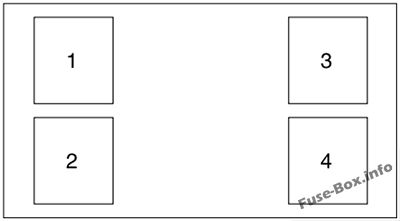
Auxiliary relay with HID headlamps
| № | Description |
|---|---|
| 1 | Left HID headlamp |
| 2 | Right HID headlamp |
| 3 | Not used |
| 4 | Not used |
2009
Passenger compartment
Assignment of the fuses in the Passenger compartment (2009)
| № | Amp Rating | Protected Circuits |
|---|---|---|
| 1 | Mini relay | Accessory delay #1 |
| 2 | — | Not used |
| 3 | 10A | Wiper power/Blower motor relay |
| 4 | 5A | Power mirrors |
| 5 | — | Not used |
| 6 | 5A | Accessory delay feeds |
| 7 | 10A | Electrochromic mirror/ Ambient lighting |
| 8 | 10A | Cluster, Data Link Connector (DLC) |
| 9 | — | Not used |
| 10 | 5A | Intrusion Sensing Module (ISM), Climate control |
| 11 | — | Not used |
| 12 | 5A | Climate control, Ignition |
| 13 | — | Not used |
| 14 | 5A | A/C cycle switch |
| 15 | 10A | Brake On/Off (BOO) power |
| 16 | 5A | Cluster |
| 17 | 10A | Restraint Control Module (RCM), Passenger Occupant Detection System (PODS), Passenger Air bag Deactivation Indicator (PADI) |
| 18 | 10A | Anti-lock Brake System (ABS) |
| 19 | 5A | Powertrain Control Module (PCM) relay, Passive Anti-Theft System (PATS), Instrument cluster airbag warning lamp |
| 20 | 10A | Radio (Start) |
| 21 | 10A | Starter relay |
Engine compartment
Assignment of the fuses in the Power distribution box (2009)
| № | Amp Rating | Protected Circuits |
|---|---|---|
| 1 | — | Not used |
| 2 | 30A* | Climate control blower |
| 3 | 40A* | Cooling fan |
| 4 | 30A* | Starter |
| 5 | 30A* | Driver front window motor |
| 6 | 30A* | Rear amplifier (Shaker 1000 radio) |
| 7 | 30A* | Passenger front window motor |
| 8 | 40A* | Anti-lock Brake System (ABS) #1 |
| 9 | 30A* | Rear amplifier (Shaker 1000 radio) |
| 10 | 30A* | Wipers |
| 11 | 30A* | Driver rear window motor (Convertible only) |
| 12 | 30A* | Passenger rear window motor (Convertible only) |
| 13 | 40A* | Convertible top |
| 14 | 30A* | Driver seat |
| 15 | 30A* | Passenger seat |
| 16 | 30A* | Front amplifier (Shaker 500/1000 radios) |
| 20 | Mini relay | PCM |
| 21 | Micro relay | Fuel pump |
| 22 | Micro relay | Starter |
| 23 | — | Not used |
| 24 | Micro relay | A/C clutch |
| 25 | Mini relay | Cooling fan (High-speed) |
| 26 | Micro relay | Horn |
| 27 | Micro relay | High beams |
| 28 | Mini relay | Cooling fan (Low-speed) |
| 29 | Mini relay | Rear defroster |
| 30 | Micro relay | Fog lamps |
| 31 | Mini relay | Convertible top (Up) |
| 32 | Mini relay | Climate control blower |
| 33 | Mini relay | Convertible top (Down) |
| 34 | Micro relay | Decklid |
| 39 | 15A** | Engine #4 |
| 40 | 15A** | Engine #2 |
| 41 | 15 A** | Fuel pump |
| 42 | 15A** | Engine #3 |
| 43 | 10A** | Alternator |
| 44 | 10A** | Delayed accessory |
| 45 | 10A** | PCM |
| 46 | 25A** | Horn |
| 47 | 15 A** | Engine #1 |
| 48 | — | Not used |
| 49 | 15 A** | A/C clutch |
| 50 | 15A** | High beams |
| 51 | 10A** | Convertible top |
| 52 | 30A** | Rear defroster |
| 53 | Diode | PCM |
| 54 | 20A** | Left HID headlamp |
| 55 | 20A** | Right HID headlamp |
| 56 | 20A** | Radio, SOARS |
| 57 | 20A** | Decklid release |
| 58 | 15A** | Fog lamps |
| 59 | 30A** | SJB #5 (Passenger compartment fuse box) |
| 60 | — | Not used |
| 61 | 20A** | Power point #1 (Instrument panel) |
| 62 | 20A** | SJB #7 (Passenger compartment fuse box) |
| 63 | 30A** | SJB #6 (Passenger compartment fuse box) |
| 64 | 20A** | Power point #2 (Console) |
| 65 | 30A** | ABS #2 |
| 66 | 25A** | Heated seats |
| 67 | 30A** | SJB #4 (Passenger compartment fuse box) |
| 68 | 20A** | Ignition |
| * Cartridge Fuses ** Mini Fuses |
Auxiliary relay with HID headlamps
| № | Description |
|---|---|
| 1 | Left HID headlamp |
| 2 | Right HID headlamp |
| 3 | Not used |
| 4 | Not used |


