


Fuse Layout Ford Fusion 2013-2016
Contents

Cigar lighter (power outlet) fuses are the fuses #5 (Power point 3 – Back ot console), #10 (Power point 1 – driver front) and #16 (Power point 2 – console) in the Engine compartment fuse box.
Table of Contents
Fuse box location
Passenger compartment
The fuse panel is located under the instrument panel to the left of the steering column (behind the trim panel below the steering wheel).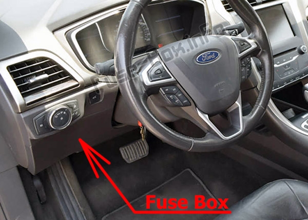
Engine compartment
The power distribution box is located in the engine compartment.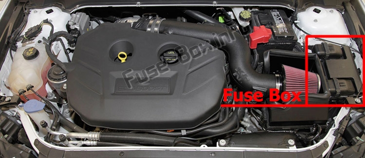
There are fuses located on the bottom of the fusebox
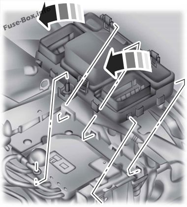
To access the bottom of the fuse box, do the following:
1. Release the two latches, located on both sides of the fusebox.
2. Raise the inboard side of the fusebox from the cradle.
3. Move the fusebox toward the center of the engine compartment.
4. Pivot the outboard side of the fusebox to access the bottom side.
Fuse box diagrams
2013, 2014
Passenger compartment
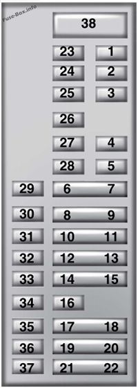
Assignment of the fuses in the Passenger compartment (2013, 2014)
| № | Amp Rating | Protected components |
|---|---|---|
| 1 | 10A | Lighting (ambient, glove box, vanity, dome, trunk) |
| 2 | 7.5A | Memory seats, Lumbar, Power mirror |
| 3 | 20A | Driver door unlock |
| 4 | 5A | Not used (spare) |
| 5 | 20A | Subwoofer amplifier |
| 6 | 10A | Not used (spare) |
| 7 | 10A | Not used (spare) |
| 8 | 10A | Not used (spare) |
| 9 | 10A | Not used (spare) |
| 10 | 5A | Keypad |
| 11 | 5A | Not used |
| 12 | 7.5 A | Climate control, Gear shift |
| 13 | 7.5 A | Steering wheel column, Cluster, Datalink logic |
| 14 | 10A | Not used |
| 15 | 10A | Datalink/Gateway module |
| 16 | 15A | Not used (spare) |
| 17 | 5A | Not used (spare) |
| 18 | 5A | Ignition, Push button stop/start |
| 19 | 5A | Passenger airbag disabled indicator, Transmission range |
| 20 | 5A | Not used (spare) |
| 21 | 5A | Humidity and in-car temperature |
| 22 | 5A | Occupant classification sensor |
| 23 | 10A | Delayed accessory (Power inverter logic, Moonroof logic) |
| 24 | 30A | Central lock/unlock |
| 25 | 30A | Driver door (window, mirror) |
| 26 | 30A | Front passenger door (window, mirror) |
| 27 | 30A | Moonroof |
| 28 | 20A | Sony amplifier |
| 29 | 30A | Rear driver side door (window) |
| 30 | 30A | Rear passenger side door (window) |
| 31 | 15 A | Not used (spare) |
| 32 | 10A | GPS, Voice control, Display, Adaptive cruise control, Radio frequency receiver |
| 33 | 20A | Radio, Active noise control |
| 34 | 30A | Run/start bus (fuse #19, 20,21,22,35,36, 37, circuit breaker) |
| 35 | 5A | Restraints control module |
| 36 | 15 A | Auto-dimming rear view mirror |
| 37 | 15 A | All-wheel drive module, Heated steering wheel module |
| 38 | 30A | Not used (spare) |
Engine compartment
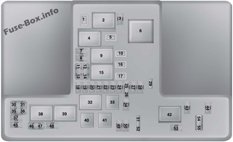
Assignment of the fuses in the Power distribution box (2013, 2014)
| № | Amp Rating | Protected components |
|---|---|---|
| 1 | 25 A | Wiper motor #2 |
| 2 | — | Starter relay |
| 3 | 15 A | Autowipers |
| 4 | — | Blower motor relay |
| 5 | 20A | Power point 3 – Back ot console |
| 6 | — | Not used |
| 7 | 20A | Powertrain control module – vehicle power 1 |
| 8 | 20A | Powertrain control module – vehicle power 2 |
| 9 | — | Powertrain control module relay |
| 10 | 20A | Power point 1 – driver front |
| 11 | 15A | Powertrain control module – vehicle power 4 |
| 12 | 15A | Powertrain control module – vehicle power 3 |
| 13 | 10A | Powertrain control module – vehicle power 5 |
| 14 | 10A | Powertrain control module – vehicle power 6 |
| 15 | — | Run/start relay |
| 16 | 20A | Power point 2 – console |
| 17 | — | Not used |
| 18 | 10A | Powertrain control module – keep alive power |
| 19 | 10A | Run/start electronic power assist steering |
| 20 | 10A | Run/start lighting |
| 21 | 15A | Run/start transmission control, Transmission oil pump start/stop |
| 22 | 10A | Air conditioner clutch solenoid |
| 23 | 15A | Run/start: blind spot information system, Rear view camera, Adaptive cruise control, Heads-up display |
| 24 | — | Not used |
| 25 | 10A | Run/start anti-lock brake system |
| 26 | 10A | Run/start powertrain control module |
| 27 | 10A | Not used (spare) |
| 28 | — | Not used |
| 29 | — | Not used |
| 30 | — | Not used |
| 31 | — | Not used |
| 32 | — | Electronic fan #1 relay |
| 33 | — | Air conditioner clutch relay |
| 34 | — | Not used |
| 35 | — | Not used |
| 36 | — | Not used |
| 37 | — | Not used |
| 38 | — | Electronic fan #2 relay |
| 39 | — | Electronic fan #3 relay |
| 40 | — | Fuel pump relay |
| 41 | — | Horn relay |
| 42 | — | Not used |
| 43 | — | Not used |
| 44 | — | Not used |
| 45 | — | Not used |
| 46 | 10A | Alternator |
| 47 | 10A | Brake on/off switch |
| 48 | 20A | Horn |
| 49 | 5A | Mass air flow monitor |
| 50 | — | Not used |
| 51 | — | Not used |
| 52 | — | Not used |
| 53 | 10A | Power seats |
| 54 | — | Not used |
| 55 | — | Not used |
Engine compartment – Bottom
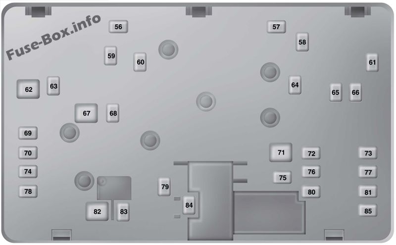
Assignment of the fuses in the Power distribution box (Bottom) (2013, 2014)
| № | Amp Rating | Protected components |
|---|---|---|
| 56 | 30A | Fuel pump feed |
| 57 | — | Not used |
| 58 | — | Not used |
| 59 | 30A | 500W Electronic fan 3 |
| 60 | 30A | 500W Electronic fan 1 |
| 61 | — | Not used |
| 62 | 50A | Body control module 1 |
| 63 | 20A | 500W Electronic fan 2 |
| 64 | — | Not used |
| 65 | 20A | Front heated seat |
| 66 | — | Not used |
| 67 | 50A | Body control module 2 |
| 68 | 40A | Heated rear window |
| 69 | 30A | Anti-lock brake system valves |
| 70 | 30A | Passenger seat |
| 71 | — | Not used |
| 72 | 30A | Not used (spare) |
| 73 | 20A | Not used (spare) |
| 74 | 30A | Driver seat module |
| 75 | — | Not used |
| 76 | 20A | Transmission oil pump #2 stop/start |
| 77 | 30A | Not used (spare) |
| 78 | — | Not used |
| 79 | 40A | Blower motor |
| 80 | 30A | Not used (spare) |
| 81 | 40A | 110 volt inverter |
| 82 | 60A | Anti-lock brake system pump |
| 83 | 25 A | Wiper motor #1 |
| 84 | 30A | Starter solenoid |
| 85 | 30A | Not used (spare) |
2015
Passenger compartment
Assignment of the fuses in the Passenger compartment (2015)
| № | Amp Rating | Protected components |
|---|---|---|
| 1 | 10A | Lighting (ambient, glove box, vanity, dome, trunk). |
| 2 | 7.5A | Memory seats, lumbar, power mirror. |
| 3 | 20A | Driver door unlock. |
| 4 | 5A | Not used (spare). |
| 5 | 20A | Subwoofer amplifier. |
| 6 | 10A | Heated seat relay coil. |
| 7 | 10A | Not used (spare). |
| 8 | 10A | Not used (spare). |
| 9 | 10A | Not used (spare). |
| 10 | 5A | Keypad. Power decklid module. |
| 11 | 5A | Not used. |
| 12 | 7.5 A | Climate control. |
| 13 | 7.5 A | Steering wheel column lock. Cluster. Datelink logic. |
| 14 | 10A | Not used. |
| 15 | 10A | Datalink gateway module. |
| 16 | 15A | Child lock. Decklid-liftglass release. |
| 17 | 5A | Not used (spare). |
| 18 | 5A | Ignition. Push button stop start switch. |
| 19 | 5A | Passenger airbag disabled indicator. Transmission range |
| 20 | 5A | Not used (spare). |
| 21 | 5A | Humidity and in-car temperature sensor. Blind spot information system. Rear video camera. Adaptive cruise control. |
| 22 | 5A | Occupant classification sensor. |
| 23 | 10A | Delayed accessory (power inverter logic, moonroof logic). |
| 24 | 20A | Central lock unlock. |
| 25 | 30A | Driver door (window, mirror). |
| 26 | 30A | Front passenger door (window, mirror). |
| 27 | 30A | Moonroof. |
| 28 | 20A | Amplifier. |
| 29 | 30A | Rear driver side door (window). |
| 30 | 30A | Rear passenger side door (window). |
| 31 | — | Spare. |
| 32 | 10A | Global positioning system. Display. Voice control. Adaptive cruise control. Radio frequency receiver. |
| 33 | 20A | Radio. |
| 34 | 30A | Run-start bus (fuse 19, 20,21,22,35, 36, 37, circuit breaker). |
| 35 | 5A | Restraints control module. |
| 36 | 15 A | Auto-dimming rear view mirror. Heated seat. All-wheel drive. |
| 37 | 15A | Voltage stability module logic power. |
| 38 | 30A | Not used (spare). |
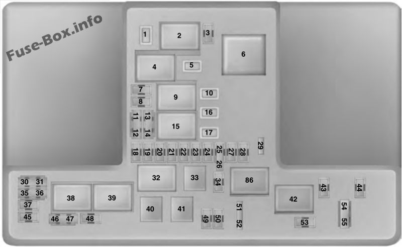
Engine compartment
Assignment of the fuses in the Power distribution box (2015)
| № | Amp Rating | Protected components |
|---|---|---|
| 1 | 30A | Moonroof 1. |
| 2 | – | Starter relay. |
| 3 | 15A | Autowipers. |
| 4 | — | Blower motor relay. |
| 5 | 20A | Power point 3 – Back of console. |
| 6 | — | Not used. |
| 7 | 20A | Powertrain control module – vehicle power 1 . |
| 8 | 20A | Powertrain control module – vehicle power 2. |
| 9 | — | Powertrain control module relay. |
| 10 | 20A | Power point 1 – driver front. |
| 11 | 15 A | Powertrain control module – vehicle power 4. |
| 12 | 15 A | Powertrain control module – vehicle power 3. |
| 13 | 10A | Powertrain control module – vehicle power 5. |
| 14 | 10A | Powertrain control module – vehicle power 6. |
| 15 | — | Run-start relay. |
| 16 | 20A | Power point 2 – console. |
| 17 | 20A | Not used (spare). |
| 18 | 20A | Not used (spare). |
| 19 | 10A | Run-start electronic power assist steering. |
| 20 | 10A | Run/start lighting. |
| 21 | 15 A | Run/start transmission control. Transmission oil pump start/stop. |
| 22 | 10A | Air conditioner clutch solenoid. |
| 23 | 15 A | Run-start. Blind spot information system. Rear view camera. Adaptive cruise control. Heads-up display. Voltage stability module. |
| 24 | 10A | Run-start 7. |
| 25 | 10A | Run-start anti-lock brake system. |
| 26 | 10A | Run-start powertrain control module. |
| 27 | 10A | Not used (spare). |
| 28 | 10A | Not used (spare). |
| 29 | 5A | Mass air flow monitor. |
| 30 | — | Not used. |
| 31 | — | Not used. |
| 32 | — | Electronic fan 1 relay. |
| 33 | — | A/C clutch relay. |
| 34 | 15A | Not used. |
| 35 | — | Not used. |
| 36 | — | Not used. |
| 37 | 10A | Not used. |
| 38 | — | Electronic fan 2 relay |
| 39 | — | Not used. |
| 40 | — | Electronic fan coil 2 and 3 relay. |
| 41 | — | Horn relay. |
| 42 | — | Fuel pump coil relay. |
| 43 | 10A | Not used. |
| 44 | 20A | Not used (spare). |
| 45 | — | Not used. |
| 46 | — | Not used. |
| 47 | — | Not used. |
| 48 | — | Not used. |
| 49 | 10A | Keep alive power. |
| 50 | 20A | Horn. |
| 51 | — | Not used. |
| 52 | — | Not used. |
| 53 | 10A | Power seats. |
| 54 | 10A | Brake on off switch. |
| 55 | 10A | ALT sensor. |
Engine compartment – Bottom
Assignment of the fuses in the Power distribution box (Bottom) (2015)
| № | Amp Rating | Protected components |
|---|---|---|
| 56 | — | Not used. |
| 57 | 30A | Diesel vaporizer or E100. |
| 58 | 30A | Fuel pump feed. |
| 59 | 30A | 500W Electronic fan 3. |
| 60 | 30A | 500W Electronic fan 1. |
| 61 | — | Not used. |
| 62 | 50A | Body control module 1. |
| 63 | 20A | 500W Electronic fan 2. |
| 64 | 30A | Not used (spare). |
| 65 | 20A | Front heated seat. |
| 66 | — | Not used. |
| 67 | 50A | Body control module 2. |
| 68 | 40A | Heated rear window. |
| 69 | 30A | Anti-lock brake system valves. |
| 70 | 30A | Passenger seat. |
| 71 | 50A | Active front steering. |
| 72 | 20A | Trans oil pump. |
| 73 | 20A | Rear heated seats. |
| 74 | 30A | Driver seat module. |
| 75 | 25 A | Wiper motor 1. |
| 76 | 30A | Power lift-gate module. |
| 77 | 30A | Climate control seat module. |
| 78 | 40A | Not used (spare). |
| 79 | 40A | Blower motor. |
| 80 | 25 A | Wiper motor 2. |
| 81 | 40A | 110 volt inverter. |
| 82 | — | Not used. |
| 83 | 25 A | TRCM shifter. |
| 84 | 30A | Starter solenoid. |
| 85 | 30A | Moonroof 2. |
| 86 | — | Not used. |
| 87 | 60A | Anti-lock brake system pump. |
2016
Passenger compartment
Assignment of the fuses in the Passenger compartment (2016)
| № | Amp Rating | Protected components |
|---|---|---|
| 1 | 10A | Lighting (ambient, glove box, vanity, dome, trunk). |
| 2 | 7.5A | Memory seats, lumbar, power mirror. |
| 3 | 20A | Driver door unlock. |
| 4 | 5A | Not used (spare). |
| 5 | 20A | Subwoofer amplifier. |
| 6 | 10A | Heated seat relay coil. |
| 7 | 10A | Not used (spare). |
| 8 | 10A | Not used (spare). |
| 9 | 10A | Not used (spare). |
| 10 | 5A | Keypad. Power decklid module. Cellphone passport module. |
| 11 | 5A | Not used (spare). |
| 12 | 7.5A | Climate control. Gear shift |
| 13 | 7.5A | Steering wheel column lock. Cluster. Datelink logic. |
| 14 | 10A | Battery electronic control module. |
| 15 | 10A | Datalink gateway module. |
| 16 | 15 A | Child lock. Decklid-liftglass release. |
| 17 | 5A | Tracking and blocking. |
| 18 | 5A | Ignition. Push button stop start switch. |
| 19 | 7.5A | Passenger airbag disabled indicator. Transmission range. |
| 20 | 7.5 A | Adaptive headlamp. |
| 21 | 5A | Humidity and in-car temperature sensor. |
| 22 | 5A | Occupant classification sensor. |
| 23 | 10A | Delayed accessory (power inverter logic, moonroof logic). |
| 24 | 20A | Central lock unlock. |
| 25 | 30A | Driver door (window, mirror). |
| 26 | 30A | Front passenger door (window, mirror). |
| 27 | 30A | Moonroof. |
| 28 | 20A | Amplifier. |
| 29 | 30A | Rear driver side door (window). |
| 30 | 30A | Rear passenger side door (window). |
| 31 | 15A | Not used (spare). |
| 32 | 10A | Global positioning system. Display. Voice control. Adaptive cruise control. Radio frequency receiver. |
| 33 | 20A | Radio. Active noise control. CD changer. |
| 34 | 30A | Run-start bus (fuse 19, 20,21, 22,35,36, 37, circuit breaker). |
| 35 | 5A | Restraints control module. |
| 36 | 15A | Auto-dimming rear view mirror. Continuous control damping suspension. Rear heated seats. |
| 37 | 15 A | All wheel drive. Heated steering wheel. |
| 38 | 30A | Not used (spare). |
Engine compartment
Assignment of the fuses in the Power distribution box (2016)
| № | Amp Rating | Protected components |
|---|---|---|
| 1 | 30A | Wide open panoramic roof 1. |
| 2 | – | Starter relay. |
| 3 | 15A | Rain sensor. |
| 4 | — | Blower motor relay. |
| 5 | 20A | Power point 3 – Back of console. |
| 6 | — | Not used. |
| 7 | 20A | Powertrain control module – vehicle power 1 . |
| 8 | 20A | Powertrain control module – vehicle power 2. |
| 9 | — | Powertrain control module relay. |
| 10 | 20A | Power point 1 – driver front. |
| 11 | 15 A | Powertrain control module – vehicle power 4. |
| 12 | 15 A | Powertrain control module – vehicle power 3. |
| 13 | 10A | Powertrain control module – vehicle power 5. |
| 14 | 10A | Powertrain control module – vehicle power 6. |
| 15 | — | Run-start relay. |
| 16 | 20A | Power point 2 – console. |
| 17 | — | Not used. |
| 18 | — | Not used. |
| 19 | 10A | Run-start electronic power assist steering. |
| 20 | 10A | Run/start lighting. |
| 21 | 15 A | Run/start transmission control. Transmission oil pump start/stop. |
| 22 | 10A | Air conditioner clutch solenoid. |
| 23 | 15 A | Run-start. Blind spot information system. Rear view camera. Adaptive cruise control. Heads-up display. Voltage stability module. |
| 24 | — | Not used. |
| 25 | 10A | Run-start anti-lock brake system. |
| 26 | 10A | Run-start powertrain control module. |
| 27 | — | Not used. |
| 28 | — | Not used. |
| 29 | 5A | Mass air flow monitor. |
| 30 | — | Not used. |
| 31 | — | Not used. |
| 32 | — | Electronic fan 1 relay. |
| 33 | — | A/C clutch relay. |
| 34 | — | Not used. |
| 35 | — | Not used. |
| 36 | — | Not used. |
| 37 | — | Not used. |
| 38 | — | Electronic fan 2 relay. |
| 39 | — | Electronic fan coil 2 and 3 relay. |
| 40 | — | Horn relay. |
| 41 | — | Not used. |
| 42 | — | Fuel pump coil relay. |
| 43 | — | Not used. |
| 44 | — | Not used. |
| 45 | — | Not used. |
| 46 | — | Not used. |
| 47 | — | Not used. |
| 48 | — | Not used. |
| 49 | 10A | Keep alive power. |
| 50 | 20A | Horn. |
| 51 | — | Not used. |
| 52 | — | Not used. |
| 53 | 10A | Power seats. |
| 54 | 10A | Brake on off switch. |
| 55 | 10A | ALT sensor. |
Engine compartment – Bottom
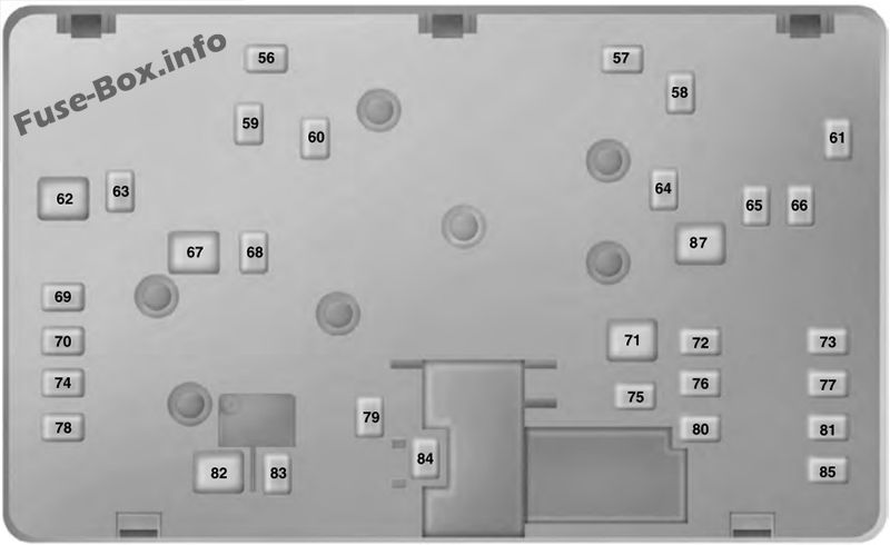
Assignment of the fuses in the Power distribution box (Bottom) (2016)
| № | Amp Rating | Protected components |
|---|---|---|
| 56 | — | Not used. |
| 57 | 20A | Diesel vaporizer or E100. |
| 58 | 30A | Fuel pump feed. |
| 59 | 30A | Electronic fan 3. |
| 60 | 30A | Electronic fan 1. |
| 61 | — | Not used. |
| 62 | 50A | Body control module 1. |
| 63 | 25A | Electronic fan 2. |
| 64 | — | Not used. |
| 65 | 20A | Front heated seat. |
| 66 | — | Not used. |
| 67 | 50A | Body control module 2. |
| 68 | 40A | Heated rear window. |
| 69 | 30A | Anti-lock brake system valves. |
| 70 | 30A | Passenger seat. |
| 71 | — | Not used. |
| 72 | 20A | Trans oil pump. |
| 73 | 20A | Rear heated seats. |
| 74 | 30A | Driver seat module. |
| 75 | 25 A | Wiper motor 1. |
| 76 | 30A | Power lift-gate module. |
| 77 | 30A | Climate control seat module. |
| 78 | 40A | Trailer tow module. |
| 79 | 40A | Blower motor. |
| 80 | 25A | Wiper motor 2. |
| 81 | 40A | Inverter. |
| 82 | — | Not used. |
| 83 | 20A | TRCM shifter. |
| 84 | 30A | Starter solenoid. |
| 85 | 30A | Wide open panoramic roof 2. |
| 86 | — | Not used. |
| 87 | 60A | Anti-lock brake system pump. |


