Fuse Layout Ford Freestar / Windstar 2004-2007
Contents
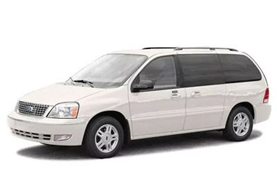
Cigar lighter (power) outlet fuses in the Ford Freestar are the fuses №57 (2004-2005: Cigar lighter), №61 (2004-2005: 3rd-row power point), №63 (2004-2005: Instrument panel power point; 2006-2007: Instrument panel power point, Cigar lighter) and №66 (2004-2005: 2nd-row seat power point; 2006-2007: 2nd and 3rd-row seat power points) in the Engine compartment fuse box.
Table of Contents
Fuse box location
Passenger compartment
The fuse panel is located below and to the left of the steering wheel by the brake pedal.
Remove the panel cover to access the fuses. To remove the fuse panel cover, pull up on the latch on the right or left side of the cover.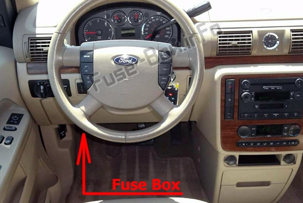
Engine compartment
The power distribution box is located in the engine compartment
Auxiliary relay box (cooling fans)
The relay box is located in the engine compartment by the radiator.
Fuse box diagrams
2004
Passenger compartment
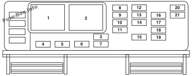
Assignment of the fuses in the Passenger compartment (2004)
| № | Amp Rating | Description |
|---|---|---|
| 1 | Relay | Accessory delay relay 1 |
| 2 | Relay | Accessory delay relay 2 |
| 3 | 10A | Front wiper motor Run feed |
| 4 | 5A | B+ feed to outside mirrors |
| 5 | 20A | Vent window power feed/Radio feed |
| 6 | 5A | Driver door switch iUumination/Passenger door switch illumination |
| 7 | 10A | Rear wiper Run feed |
| 8 | 10A | Cluster/Electronic Automatic Temperature Control (EATC) B+ feed |
| 9 | 10A | Passive Anti-theft System (PATS) LED feed |
| 10 | 5A | Auxiliary radio, DVD |
| 11 | 5A | Auxiliary climate control system/Power Liftgate Module/Left and right power sliding door module/Data Link Connector (DLC)/Clock B+ feeds |
| 12 | 5A | Brake-Shift Interlock (BSI) Run feed, Climate control system Run feed |
| 13 | 5A | Compass/Driver heated seat/Passenger heated seats/Reverse sensing system/Power Liftgate Module/Power sliding door Run feeds |
| 14 | 5A | Underhood fuse box Run feed, Front blower Run feed |
| 15 | 10A | Brake On-Off (BOO) switch B+ |
| 16 | 5A | Steering angle/Cluster/Power sliding door and power liftgate inhibit LED/Electrochromatic mirror Run/Start |
| 17 | 10A | Restraint Control Module (RCM)/Passenger Air bag Disable Indicator (PADI)/Passenger Occupant Detection System (PODS) Run/Start |
| 18 | 10A | Anti-lock Brake System (ABS) module/Brake pressure switch/Speed control Run/Start |
| 19 | 5A | PATS/Cluster/Air bag LED/Powertrain Control Module (PCM) relay Run/Start |
| 20 | 10A | Liftgate Start feed, Radio Start feed |
| 21 | 10A | Starter relay power START |
Engine compartment
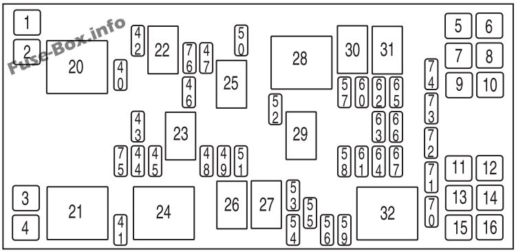
Assignment of the fuses in the Power distribution box (2004)
| № | Amp Rating | Description |
|---|---|---|
| 1 | — | Not used |
| 2 | 30A** | Right cooling fan |
| 3 | 30A** | Left cooling fan |
| 4 | 30A** | Starter solenoid |
| 5 | 30A** | Right-hand power sliding door |
| 6 | 30A** | SJB accessoiy #2 (driver power window) |
| 7 | 30A** | Auxiliary blower motor |
| 8 | 40A** | Anti-lock Brake System (ABS) #2 (coil power) |
| 9 | 30A** | Power liftgate |
| 10 | 30A** | SJB accessoiy #1 (passenger window, radio, vent windows) |
| 11 | 30A** | Left power seat/heated seat |
| 12 | 40A** | ABS #1 (pump motor) |
| 13 | 40A** | Rear defroster |
| 14 | 30A** | Front climate control system blower motor |
| 15 | 30A** | Right power seat/heated seat |
| 16 | 30A** | Left-hand power sliding door |
| 20 | Mini relay | Powertrain Control Module (PCM) power |
| 21 | Mini relay | Horn |
| 22 | Micro relay | A/C clutch |
| 23 | Micro relay | High beams |
| 24 | Mini relay | Starter |
| 25 | Micro relay | Fuel pump |
| 26 | — | Not used |
| 27 | — | Not used |
| 28 | Mini relay | Auxiliary blower |
| 29 | Micro relay | Trailer park lamps |
| 30 | Micro relay | Left trailer stop/turn lamps |
| 31 | Micro relay | Right trailer stop/turn lamps |
| 32 | Mini relay | Rear defroster |
| 40 | 15 A* | Engine #1 (A/C relay coil, IMRC, HEGO sensors, Canister purge, Transaxle, Canister vent) |
| 41 | 25A* | Horn |
| 42 | 10 A* | A/C clutch |
| 43 | 15 A* | Engine #2 (Cooling fan relays, Injectors, PCM, MAF sensor, IAC, Ignition coil, ESM) |
| 44 | 10 A* | Heated PCV |
| 45 | 15 A* | High beams |
| 46 | 20 A* | Trailer stop/turn lamps |
| 47 | 15 A* | Fuel pump driver module |
| 48 | — | Not used |
| 49 | 10 A* | PCM KAP |
| 50 | 10 A* | Alternator |
| 51 | 10 A* | Adjustable pedals (non-memory) or memory module |
| 52 | 20 A* | Trailer tow park lamps |
| 53 | 10 A* | Heated mirrors |
| 54 | 30A* | Front wiper motor |
| 55 | 25A* | Rear wiper motor |
| 56 | 30A* | Premium sound radio |
| 57 | 20 A* | Cigar lighter |
| 58 | 30A* | SJB #1 – Center High-Mounted Stop Lamp (CHMSL), License plate lamps, OBD II, Dome lamp, Auxiliary blend doors, Switch illumination (feeds F-8, F-9, F-10 and F-ll) |
| 59 | 20 A* | Radio (non-premium) |
| 60 | 30A* | SJB #4 – Back-up lamps, Theft sounder, Door locks |
| 61 | 20 A* | 3rd row power point |
| 62 | 30A* | SJB #3 – Right cornering/auxiliary lamps, Right low beam, Left front park/turn lamps, Left rear park/stop/turn lamps, Instrument panel courtesy lamps, Step well lamps, Left signal mirror, Clock, Cluster, Message center (SJB F-15), Switch illumination for: overhead console, DVD/Rear climate control system, Headlamp switch illumination, Climate control illumination |
| 63 | 20 A* | Instrument panel power point |
| 64 | 20 A* | Ignition switch #1 feed |
| 65 | 30A* | SJB #2 – Left cornering/auxiliary lamps, Left low beam, Right front park/turn lamps, Right rear park/stop/turn lamps, Puddle lamps, Mirror signals, Visors, 2nd and 3rd row lamps, Cargo lamp, Defroster indicator |
| 66 | 20 A* | 2nd row seat power point |
| 67 | 20 A* | Ignition switch #2 feed |
| 70 | — | Not used |
| 71 | — | Not used |
| 72 | — | Not used |
| 73 | — | Not used |
| 74 | — | Not used |
| 75 | Diode | PCM |
| 76 | Diode | A/C clutch |
| * Mini Fuse ** Cartridge Fuse |
2005
Passenger compartment

Assignment of the fuses in the Passenger compartment (2005)
| № | Amp Rating | Description |
|---|---|---|
| 1 | Relay | Accessory delay relay 1 |
| 2 | Relay | Accessory delay relay 2 |
| 3 | 10A | Front wiper motor Run feed |
| 4 | 5A | B+ feed to outside mirrors |
| 5 | 20A | Vent window power feed/Radio feed |
| 6 | 5A | Driver door switch iUumination/Passenger door switch illumination |
| 7 | 10A | Rear wiper Run feed |
| 8 | 10A | Cluster/Electronic Automatic Temperature Control (EATC) B+ feed, DVD |
| 9 | 10A | Passive Anti-theft System (PATS) LED feed |
| 10 | 5A | Auxiliary radio |
| 11 | 5A | Auxiliary climate control system/Power Liftgate Module/Left and right power sliding door module/Data Link Connector (DLC)/Clock B+ feeds |
| 12 | 5A | Brake-Shift Interlock (BSI) Run feed, Climate control system Run feed |
| 13 | 5A | Compass/Driver heated seat/Passenger heated seats/Reverse sensing system/Power Liftgate Module/Power sliding door Run feeds |
| 14 | 5A | Underhood fuse box Run feed, Front blower Run feed |
| 15 | 10A | Brake On-Off (BOO) switch B+ |
| 16 | 5A | Steering angle/Cluster/Power sliding door and power liftgate inhibit LED/Electrochromatic mirror Run/Start/Tire Pressure Monitoring System (TPMS) |
| 17 | 10A | Restraint Control Module (RCM)/Passenger Air bag Disable Indicator (PADI)/Passenger Occupant Detection System (PODS) Run/Start |
| 18 | 10A | Anti-lock Brake System (ABS) module/Brake pressure switch/Speed control Run/Start |
| 19 | 5A | PATS/Cluster/Air bag LED/Powertrain Control Module (PCM) relay Run/Start |
| 20 | 10A | Liftgate Start feed, Radio Start feed |
| 21 | 10A | Starter relay power START |
Engine compartment

Assignment of the fuses in the Power distribution box (2005)
| № | Amp Rating | Description |
|---|---|---|
| 1 | — | Not used |
| 2 | 30A** | Right cooling fan |
| 3 | 30A** | Left cooling fan |
| 4 | 30A** | Starter solenoid |
| 5 | 30A** | Right-hand power sliding door |
| 6 | 30A** | SJB accessory #2 (driver power window) |
| 7 | 30A** | Auxiliary blower motor |
| 8 | 40A** | Anti-lock Brake System (ABS) #2 (coil power) |
| 9 | 30A** | Power liftgate |
| 10 | 30A** | SJB accessory #1 (passenger window, radio, vent windows) |
| 11 | 30A** | Left power seat/heated seat |
| 12 | 40A** | ABS #1 (pump motor) |
| 13 | 40A** | Rear defroster |
| 14 | 30A** | Front climate control system blower motor |
| 15 | 30A** | Right power seat/heated seat |
| 16 | 30A** | Left-hand power sliding door |
| 20 | Mini relay | Powertrain Control Module (PCM) power |
| 21 | Mini relay | Horn |
| 22 | Micro relay | A/C clutch |
| 23 | Micro relay | High beams |
| 24 | Mini relay | Starter |
| 25 | Micro relay | Fuel pump |
| 26 | — | Not used |
| 27 | — | Not used |
| 28 | Mini relay | Auxiliary blower |
| 29 | Micro relay | Trailer park lamps |
| 30 | Micro relay | Left trailer stop/turn lamps |
| 31 | Micro relay | Right trailer stop/turn lamps |
| 32 | Mini relay | Rear defroster |
| 40 | 15 A* | Engine #1 (A/C relay coil, IMRC, HEGO sensors, Canister purge, Transaxle, Canister vent) |
| 41 | 25A* | Horn |
| 42 | 10 A* | A/C clutch |
| 43 | 15 A* | Engine #2 (Cooling fan relays, Injectors, PCM, MAF sensor, LAC, Ignition coil, ESM) |
| 44 | 10 A* | Heated PCV |
| 45 | 15 A* | High beams |
| 46 | 20 A* | Trailer stop/turn lamps |
| 47 | 15 A* | Fuel pump driver module |
| 48 | — | Not used |
| 49 | 10 A* | PCM KAP |
| 50 | 10 A* | Alternator |
| 51 | 10 A* | Adjustable pedals (non-memory) or memory module |
| 52 | 20 A* | Trailer tow park lamps |
| 53 | 10 A* | Heated mirrors |
| 54 | 30A* | Front wiper motor |
| 55 | 25A* | Rear wiper motor |
| 56 | 30A* | Premium sound radio |
| 57 | 20A* | Cigar lighter |
| 58 | 30A* | SJB #1 – Center High-Mounted Stop Lamp (CHMSL), License plate lamps, OBD II, Dome lamp, Auxiliary blend doors, Switch illumination (feeds F-8, F-9, F-10 and F-ll) |
| 59 | 20 A* | Radio (non-premium) |
| 60 | 30A* | SJB #4 – Back-up lamps, Door locks |
| 61 | 20 A* | 3rd row power point |
| 62 | 30A* | SJB #3 – Right cornering/auxiliary lamps, Right low beam, Left front park/turn lamps, Left rear park/stop/turn lamps, Instrument panel courtesy lamps, Step well lamps, Left signal mirror, Clock, Cluster, Message center (SJB F-15), Switch illumination for: overhead console, DVD/Rear climate control system, Headlamp switch illumination, Climate control illumination |
| 63 | 20 A* | Instrument panel power point |
| 64 | 20 A* | Ignition switch #1 feed |
| 65 | 30A* | SJB #2 – Left cornering/auxiliary lamps, Left low beam, Right front park/turn lamps, Right rear park/stop/turn lamps, Puddle lamps, Mirror signals, Visors, 2nd and 3rd row lamps, Cargo lamp, Defroster indicator |
| 66 | 20 A* | 2nd row seat power point |
| 67 | 20 A* | Ignition switch #2 feed |
| 70 | — | Not used |
| 71 | — | Not used |
| 72 | — | Not used |
| 73 | — | Not used |
| 74 | — | Not used |
| 75 | Diode | PCM |
| 76 | Diode | A/C clutch |
| * Mini Fuse ** Cartridge Fuse |
Auxiliary relay box
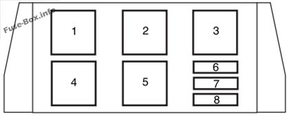
| № | Amp Rating | Description |
|---|---|---|
| 1 | — | Cooling fan relay #4 |
| 2 | — | Cooling fan relay #5 |
| 3 | — | Cooling fan relay #3 |
| 4 | — | Cooling fan relay #1 |
| 5 | — | Cooling fan relay #2 |
| 6 | 40A* | Right-hand cooling fan motor (Vehicles with trailer tow package only) |
| 7 | 15A** | Low-speed cooling fan circuit breaker (Vehicles ‘with trailer tow package only) |
| 8 | 40A* | Left-hand cooling fan motor (Vehicles with trailer tow package) |
| 8 | 10A** | Low-speed cooling fan circuit breaker (Vehicles ‘without trailer tow package) |
| * Maxi fuse ** Circuit breaker |
2006, 2007
Passenger compartment

Assignment of the fuses in the Passenger compartment (2006, 2007)
| № | Amp Rating | Description |
|---|---|---|
| 1 | Relay | Accessory delay relay 1 |
| 2 | Relay | Accessory delay relay 2 |
| 3 | 10A | Front wiper motor Run feed |
| 4 | 5A | B+ feed to outside mirrors |
| 5 | 20A | Vent window power feed/Radio feed |
| 6 | 5A | Driver door switch iUumination/Passenger door switch illumination |
| 7 | 10A | Rear wiper Run feed |
| 8 | 10A | Cluster/Electronic Automatic Temperature Control (EATC) B+ feed, DVD |
| 9 | 10A | Passive Anti-theft System (PATS) LED feed |
| 10 | 5A | Auxiliary radio |
| 11 | 5A | Auxiliary climate control system/Power Liftgate Module/Left and right power sliding door module/Data Link Connector (DLC)/Clock B+ feeds |
| 12 | 5A | Brake-Shift Interlock (BSI) Run feed, Climate control system Run feed |
| 13 | 5A | Compass/Driver heated seat/Passenger heated seats/Reverse sensing system/Power Liftgate Module/Power sliding door Run feeds |
| 14 | 5A | Underhood fuse box Run feed, Front blower Run feed |
| 15 | 10A | Brake On-Off (BOO) switch B+ |
| 16 | 5A | Steering angle/Cluster/Power sliding door and power liftgate inhibit LED/Electrochromatic mirror Run/Start/Tire Pressure Monitoring System (TPMS) |
| 17 | 10A | Restraint Control Module (RCM)/Passenger Air bag Disable Indicator (PADI)/Passenger Occupant Detection System (PODS) Run/Start |
| 18 | 10A | Anti-lock Brake System (ABS) module/Brake pressure switch/Speed control Run/Start |
| 19 | 5A | PATS/Cluster/Air bag LED/Powertrain Control Module (PCM) relay Run/Start |
| 20 | 10A | Liftgate Start feed, Radio Start feed |
| 21 | 10A | Starter relay power START |
Engine compartment

Assignment of the fuses in the Power distribution box (2006, 2007)
| № | Amp Rating | Description |
|---|---|---|
| 1 | — | Not used |
| 2 | 30A** | Right cooling fan |
| 3 | 30A** | Left cooling fan |
| 4 | 30A** | Starter solenoid |
| 5 | 30A** | Right-hand power sliding door |
| 6 | 30A** | SJB accessoiy #2 (driver power window) |
| 7 | 30A** | Auxiliary blower motor |
| 8 | 40A** | Anti-lock Brake System (ABS) #2 (coil power) |
| 9 | 30A** | Power liftgate |
| 10 | 30A** | SJB accessoiy #1 (passenger window, radio, vent windows) |
| 11 | 30A** | Left power seat/heated seat |
| 12 | 40A** | ABS #1 (pump motor) |
| 13 | 40A** | Rear defroster |
| 14 | 30A** | Front climate control system blower motor |
| 15 | 30A** | Right power seat/heated seat |
| 16 | 30A** | Left-hand power sliding door |
| 20 | Mini relay | Powertrain Control Module (PCM) power |
| 21 | Mini relay | Horn |
| 22 | Micro relay | A/C clutch |
| 23 | Micro relay | High beams |
| 24 | Mini relay | Starter |
| 25 | Micro relay | Fuel pump |
| 26 | — | Not used |
| 27 | — | Not used |
| 28 | Mini relay | Auxiliary blower |
| 29 | Micro relay | Trailer park lamps |
| 30 | Micro relay | Left trailer stop/turn lamps |
| 31 | Micro relay | Right trailer stop/turn lamps |
| 32 | Mini relay | Rear defroster |
| 40 | 15 A* | Engine #1 (A/C relay coil, IMRC, HEGO sensors, Canister purge, Transmission module) |
| 41 | 25A* | Horn |
| 42 | 10 A* | A/C clutch |
| 43 | 15 A* | Engine #2 (Cooling fan relays, Injectors, PCM, MAF sensor, IAC, Ignition coil, ESM) |
| 44 | 10 A* | Heated PCV |
| 45 | 15 A* | High beams |
| 46 | 20 A* | Trailer stop/turn lamps |
| 47 | 15 A* | Fuel pump, Fuel pump shut-off switch |
| 48 | 15 A* | Fog lamps |
| 49 | 10 A* | PCM KAP, Canister vent |
| 50 | 10 A* | Alternator |
| 51 | 10 A* | Adjustable pedals (non-memory) or memory module |
| 52 | 20 A* | Trailer tow park lamps |
| 53 | 10 A* | Heated mirrors |
| 54 | 30A* | Front wiper motor |
| 55 | 25A* | Rear wiper motor |
| 56 | 30A* | Premium sound radio |
| 57 | — | Not used |
| 58 | 30A* | SJB #1 – Center High-Mounted Stop Lamp (CHMSL), License plate lamps, OBD II, Dome lamp, Auxiliary blend doors, Switch illumination (feeds F-8, F-9, F-10 and F-l 1) |
| 59 | 20 A* | Radio (non-premium) |
| 60 | 30A* | SJB #4 – Back-up lamps, Door locks |
| 61 | — | Not used |
| 62 | 30A* | SJB #3 – Right cornering/auxiliary lamps, Right low beam, Left front park/turn lamps, Left rear park/stop/turn lamps, Instrument panel courtesy lamps, Step well lamps, Left signal mirror, Clock, Cluster, Message center (SJB F-15), Switch illumination for: overhead console, DVD/Rear climate control system, Headlamp switch illumination, Climate control illumination |
| 63 | 20 A* | Instrument panel power point, Cigar lighter |
| 64 | 20 A* | Ignition switch #1 feed |
| 65 | 30A* | SJB #2 – Left cornering/auxiliary lamps, Left low beam, Right front park/turn lamps, Right rear park/stop/turn lamps, Puddle lamps, Mirror signals, Visors, 2nd and 3rd row lamps, Cargo lamp, Defroster indicator |
| 66 | 20 A* | 2nd and 3rd row seat power points |
| 67 | 20 A* | Ignition switch #2 feed |
| 70 | — | Not used |
| 71 | — | Not used |
| 72 | — | Not used |
| 73 | — | Not used |
| 74 | — | Not used |
| 75 | Diode | PCM |
| 76 | Diode | A/C clutch |
| * Mini Fuse ** Cartridge Fuse |
Auxiliary relay box

| № | Amp Rating | Description |
|---|---|---|
| 1 | — | Cooling fan relay #4 |
| 2 | — | Cooling fan relay #5 |
| 3 | — | Cooling fan relay #3 |
| 4 | — | Cooling fan relay #1 |
| 5 | — | Cooling fan relay #2 |
| 6 | 40A* | Right-hand cooling fan motor (Vehicles with trailer tow package only) |
| 7 | 15A** | Low-speed cooling fan circuit breaker (Vehicles ‘with trailer tow package only) |
| 8 | 40A* | Left-hand cooling fan motor (Vehicles with trailer tow package) |
| 8 | 10A** | Low-speed cooling fan circuit breaker (Vehicles ‘without trailer tow package) |
| * Maxi fuse ** Circuit breaker |


