

See other Ford Flex:

Fuse Layout Ford Flex 2009-2012
Contents

Cigar lighter (power outlet) fuses are the fuses №6, №18, №19 and №21 in the Engine compartment fuse box.
Table of Contents
Fuse box location
Passenger compartment
The fuse panel is located under the instrument panel to the left of the steering wheel.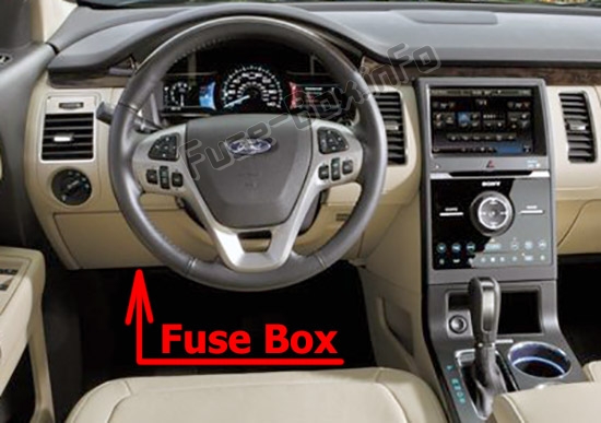
Engine compartment
The power distribution box is located in the engine compartment.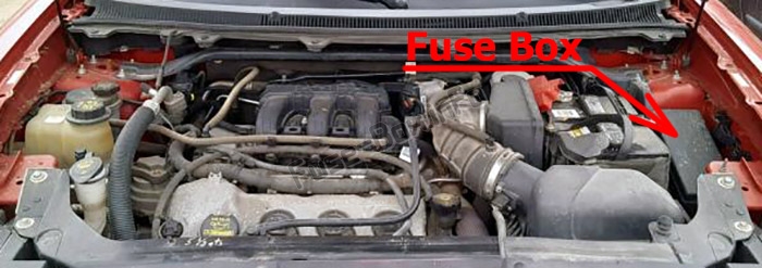
Auxiliary relay box (if equipped)
The relay box is located in the engine compartment next to the power distribution box.
Fuse box diagrams
2009
Passenger compartment
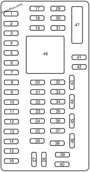
Assignment of the fuses in the Passenger compartment (2009)
| № | Amp Rating | Protected Circuits |
|---|---|---|
| 1 | 30A | Driver smart window motor |
| 2 | 15A | Not used (spare) |
| 3 | 15A | Family entertainment system (FES) |
| 4 | 30A | DC/AC inverter |
| 5 | 10A | Passenger compartment fuse panel logic power, Keypad illumination, BTSI |
| 6 | 20A | Turn signals |
| 7 | 10A | Low beam headlamps (left) |
| 8 | 10A | Low beam headlamps (right) |
| 9 | 15A | Interior lights, Cargo lamps |
| 10 | 15A | Backlighting, Puddle lamps |
| 11 | 10A | All wheel drive |
| 12 | 7.5A | Not used (spare) |
| 13 | 5A | Keypad, Mirror switch, Memory module, DSM logic, Adjustable pedals |
| 14 | 10A | Power liftgate module, CID, MGM |
| 15 | 10A | Climate control head |
| 16 | 15A | EFP, Navigation Screen |
| 17 | 20A | All power lock motor feeds, Liftgate release |
| 18 | 20A | 2nd row power seat, Front heated seats |
| 19 | 25A | Moon roof |
| 20 | 15A | OBDII connector, Memory seat |
| 21 | 15A | Fog lamps |
| 22 | 15A | Park lamps, License lamps |
| 23 | 15A | High beam headlamps |
| 24 | 20A | Horn relay |
| 25 | 10A | Demand lamps/Interior lamps, Power fold seat (2nd row) |
| 26 | 10A | Instrument panel cluster |
| 27 | 20A | Ignition Switch |
| 28 | 5A | Radio, Radio start signal |
| 29 | 5A | Instrument panel cluster |
| 30 | 5A | Overdrive cancel and grade assist switch |
| 31 | 10A | Not used (spare) |
| 32 | 10A | Restraint control module |
| 33 | 10A | Battery charge relay |
| 34 | 5A | Yaw rate sensor, ABS R/S, Refrigerator relay coil |
| 35 | 10A | Steering rotation sensor, Rear park assist, Heated seat modules, AWT), DC/AC inverter |
| 36 | 5A | PATS module |
| 37 | 10A | Not used (spare) |
| 38 | 20A | Not used (spare) |
| 39 | 20A | Radio |
| 40 | 20A | Second row heated seats |
| 41 | 15A | Swatch illumination, EC mirror, Moon roof, Front lock swatches, Radio |
| 42 | 10A | Not used (spare) |
| 43 | 10A | Aux relay, Heated back light relay, rear wiper |
| 44 | 10A | Not used (spare) |
| 45 | 5A | Relay coils: PDB, Front and rear wipers, Front blower motor |
| 46 | 7.5A | Occupant Classification Sensor (OCS), Passenger Airbag Deactivation Indicator (PADI) |
| 47 | 30A Circuit Breaker | Power windows |
| 48 | Full ISO relay | Delayed accessoiy relay |
Engine compartment
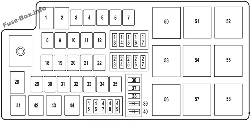
Assignment of the fuses in the Power distribution box (2009)
| № | Amp Rating | Protected Circuits |
|---|---|---|
| 1 | 80A* | Passenger compartment fuse panel power |
| 2 | 80A* | Passenger compartment fuse panel power |
| 3 | — | Not used |
| 4 | 30A* | Front wipers |
| 5 | 30A* | Passenger power seat |
| 6 | 20 A* | Power point (instrument panel) |
| 7 | 30A* | Amp |
| 8 | — | Not used |
| 9 | 40A* | Anti-lock Brake System (ABS)/AdvanceTrac pump |
| 10 | 30A* | Starter |
| 11 | 30A* | Powertrain Control Module (PCM) relay |
| 12 | 20 A* | ABS/AdvanceTrac valve |
| 13 | 20A** | Left HID |
| 14 | 10A** | Brake on/off (BOO) switch |
| 15 | 15A** | Refrigerator |
| 16 | 20A** | Right HID |
| 17 | 10A** | Alternator |
| 18 | 20 A* | Rear quarter panel power point |
| 19 | 20 A* | Power point (front console) |
| 20 | 40A* | Rear defroster |
| 21 | 20 A* | Rear console power point |
| 22 | 20 A* | Sub woofer amp |
| 23 | 7.5 A** | PCM Keep alive power, Canister vent |
| 24 | 10A** | A/C clutch relay |
| 25 | 25A** | Rear wiper |
| 26 | 20A** | Backup relay |
| 27 | 15 A** | Fuel relay (Fuel pump driver module, Fuel pump) |
| 28 | 80A* | Cooling fan |
| 29 | 30A* | E-brake (trailer tow) |
| 30 | 40A* | Battery charge (trailer tow) |
| 31 | 30A* | Auxiliary blower relay |
| 32 | 30A* | Driver seat motors, Memory module |
| 33 | — | Not used |
| 34 | 30A* | Power liftgate |
| 35 | 40A* | Front A/C blower motor |
| 36 | 10A** | Back up lamps |
| 37 | 10A** | PCM run/start |
| 38 | 5A** | Illumination delayed accessory |
| 39 | Diode | Fuel diode |
| 40 | Diode | OTIS diode |
| 41 | G8VA relay | A/C clutch |
| 42 | G8VA relay | Fuel pump |
| 43 | G8VA relay | Backup |
| 44 | G8VA relay | Refrigerator |
| 45 | — | Not used |
| 46 | 15A** | VPWR2, VPWR3 |
| 47 | 15A** | PCM VPWR1 |
| 48 | 15A** | PCM VPWR4 |
| 49 | 10A** | Heated mirrors |
| 50 | Full ISO relay | PCM relay |
| 51 | Full ISO relay | Blower motor relay |
| 52 | Full ISO relay | Starter relay |
| 53 | Full ISO relay | Rear defrost relay |
| 54 | Full ISO relay | Auxiliary blower motor relay |
| 55 | Full ISO relay | Front wiper relay |
| 56 | — | Not used |
| 57 | Full ISO relay | Rear wiper relay |
| 58 | High current | Battery charge relay (trailer tow) |
| * Cartridge Fuses ** Mini Fuses |
Auxiliary relay box
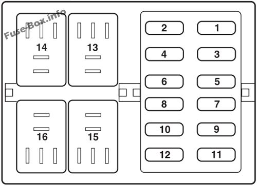
Auxiliary relay box
| № | Amp Rating | Description |
|---|---|---|
| 1 | 10A | Trailer tow backup lamp |
| 2 | 15A | Trailer tow stop/turn lamps |
| 3 | — | Not used |
| 4 | — | Not used |
| 5 | — | Not used |
| 6 | — | Not used |
| 7 | — | Not used |
| 8 | — | Not used |
| 9 | — | Not used |
| 10 | — | Not used |
| 11 | — | Not used |
| 12 | 20A | Trailer tow park lamps |
| 13 | Micro ISO | Trailer tow left turn |
| 14 | Micro ISO | Trailer tow right turn |
| 15 | — | Not used |
| 16 | Micro ISO | Trailer tow park lamp |
2010
Passenger compartment
Assignment of the fuses in the Passenger compartment (2010)
| № | Amp Rating | Protected Circuits |
|---|---|---|
| 1 | 30A | Driver smart window motor |
| 2 | 15A | Trailer tow stop/turn lamps |
| 3 | 15A | Not used (spare) |
| 4 | 30A | DC/AC inverter |
| 5 | 10A | Keypad illumination, 3rd row passenger seats, Brake transmission shift interlock |
| 6 | 20A | Turn signals |
| 7 | 10A | Low beam headlamps (left) |
| 8 | 10A | Low beam headlamps (right) |
| 9 | 15A | Interior lights, Cargo lamps |
| 10 | 15A | Backlighting, Puddle lamps |
| 11 | 10A | All wheel drive (AWD) |
| 12 | 7.5A | Not used (spare) |
| 13 | 5A | Keypad, Mirror switch, Memory module, DSM logic, Adjustable pedals |
| 14 | 10A | Power liftgate module, Center information display, SYNC®, GPS module |
| 15 | 10A | Climate control head |
| 16 | 15A | Electronic finish panel, Navigation Screen |
| 17 | 20A | All power lock motor feeds, Liftgate release |
| 18 | 20A | 2nd row power fold seats, Heated seats |
| 19 | 25A | Moon roof |
| 20 | 15A | Data link connector, Memory seat |
| 21 | 15A | Fog lamps, Fog lamp indicator |
| 22 | 15A | Park lamps |
| 23 | 15A | High beam headlamps |
| 24 | 20A | Horn |
| 25 | 10A | Demand lamps/Interior lamps, Power fold seats |
| 26 | 10A | Instrument panel cluster |
| 27 | 20A | Ignition Switch |
| 28 | 5A | Radio/navigation |
| 29 | 5A | Instrument panel cluster |
| 30 | 5A | Transmission shifter |
| 31 | 10A | Not used (spare) |
| 32 | 10A | Restraint control module |
| 33 | 10A | Not used (spare) |
| 34 | 5A | Roll stability control, Refrigerator relay coil |
| 35 | 10A | Steering angle sensor, Rear park assist, Active park assist, Heated seat, AWD, DC/AC inverter |
| 36 | 5A | Passive anti-theft system module |
| 37 | 10A | Not used (spare) |
| 38 | 20A | Trailer tow park lamps |
| 39 | 20A | Radio/navigation |
| 40 | 20A | Rear heated seats |
| 41 | 15A | Switch illumination, Auto dimming mirror, Moon roof, Mood lighting |
| 42 | 10A | Not used (spare) |
| 43 | 10A | Auxiliary climate control relay, Rear window defroster relay, Rear wiper |
| 44 | 10A | Not used (spare) |
| 45 | 5A | Wiper relay, climate control relay |
| 46 | 7.5A | Occupant classification sensor (OCS), Passenger airbag deactivation indicator (PADI) |
| 47 | 30A Circuit Breaker | Power windows |
| 48 | Full ISO relay | Delayed accessory relay |
Engine compartment
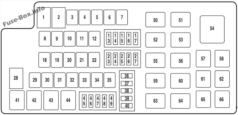
Assignment of the fuses in the Power distribution box (2010)
| № | Amp Rating | Protected Circuits |
|---|---|---|
| 1 | 80A* | Passenger compartment fuse panel power |
| 2 | 80A* | Passenger compartment fuse panel power |
| 3 | 30A* | Trailer tow brake controller |
| 4 | 30A* | Front wipers |
| 5 | 30A* | Passenger power seat |
| 6 | 20A* | Power point (instrument panel) |
| 7 | 30A* | Amplifier |
| 8 | — | Not used |
| 9 | 40A* | Anti-lock brake system (ABS) pump |
| 10 | 30A* | Starter relay |
| 11 | 30A* | Powertrain control module (PCM) relay |
| 12 | 20A* | ABS valve |
| 13 | 20 A** | Left high intensity discharge (HID) headlamp |
| 14 | 10 A** | Brake on/off (BOO) switch |
| 15 | 25A** | Rear wiper |
| 16 | 20 A** | Right HID headlamp |
| 17 | 10 A** | Alternator sensor |
| 18 | 20A* | Rear power point |
| 19 | 20A* | Instrument panel power point |
| 20 | 40A* | Rear defroster |
| 21 | 20A* | Console power point |
| 22 | 20A* | Subwoofer amplifier |
| 23 | 10 A** | PCM keep alive power, Canister vent |
| 24 | 10 A** | A/C clutch |
| 25 | 15A** | Refrigerator |
| 26 | 20 A** | Backup relay |
| 27 | 15A** | Fuel relay (Fuel pump driver module, Fuel pump) |
| 28 | 80A* | Cooling fan |
| 29 | — | Not used |
| 30 | 30A* | Battery charge (trailer tow) |
| 31 | 40A* | Auxiliary blower motor |
| 32 | 30A* | Driver seat motor |
| 33 | 30A* | 3rd row power seats |
| 34 | 30A* | Power liftgate |
| 35 | 40A* | Front A/C blower |
| 36 | 10 A** | Backup lamps |
| 37 | 10 A** | PCM run/start |
| 38 | 10 A** | Trailer tow backup lamps |
| 39 | Diode | Fuel diode |
| 40 | Diode | One touch integrated start diode |
| 41 | G8VA relay | Trailer tow park lamp |
| 42 | G8VA relay | Trailer tow stop/turn lamp (left) |
| 43 | G8VA relay | Trailer tow stop/turn lamp (right) |
| 44 | G8VA relay | Backup lamps relay |
| 45 | — | Not used |
| 46 | 15A** | Vehicle power 2, Vehicle power 3 |
| 47 | 15A** | Vehicle power 1 – PCM power (base engine only) |
| 47 | 20 A** | Vehicle power 1 – PCM power (EcoBoost only) |
| 48 | 15A** | Vehicle power – coils |
| 49 | 10 A** | Heated mirrors |
| 50 | HC micro relay | Blower motor |
| 51 | HC micro relay | Rear wiper |
| 52 | HC micro relay | Starter |
| 53 | HC micro relay | 3rd row power seats |
| 54 | — | Not used |
| 55 | HC micro relay | Front wiper relay |
| 56 | HC micro relay | Rear window defroster |
| 57 | — | Not used |
| 58 | — | Not used |
| 59 | HC micro relay | Auxiliary blower motor |
| 60 | HC micro relay | Trailer tow battery charge |
| 61 | — | Not used |
| 62 | G8VA relay | Refrigerator |
| 63 | — | Not used |
| 64 | HC micro relay | PCM |
| 65 | G8VA relay | A/C clutch |
| 66 | G8VA relay | Fuel pump |
| * Cartridge Fuses ** Mini Fuses |
2011
Passenger compartment
Assignment of the fuses in the Passenger compartment (2011)
| № | Amp Rating | Protected Circuits |
|---|---|---|
| 1 | 30A | Driver smart window motor |
| 2 | 15A | Trailer tow (TT) stop/turn lamps |
| 3 | 15A | Not used (spare) |
| 4 | 30A | DC/AC inverter |
| 5 | 10A | Keypad illumination, Brake transmission shift interlock |
| 6 | 20A | Turn signals |
| 7 | 10A | Low’ beam headlamps (left) |
| 8 | 10A | Low’ beam headlamps (right) |
| 9 | 15A | Interior lights, Cargo lamps |
| 10 | 15A | Backlighting, Puddle lamps |
| 11 | 10A | All wheel drive (AWD) |
| 12 | 7.5A | Not used (spare) |
| 13 | 5A | Keypad, Mirror switch, Memory module, DSM logic, Adjustable pedals |
| 14 | 10A | Power liftgate module, Center information display, SYNC®, Global positioning system (GPS) module, DVD |
| 15 | 10A | Climate control head |
| 16 | 15A | Electronic finish panel, Navigation screen |
| 17 | 20A | All power lock motor feeds, Liftgate release |
| 18 | 20A | 2nd row power fold seats, Heated seats |
| 19 | 25A | Moon roof |
| 20 | 15A | Data link connector, Memory seat |
| 21 | 15A | Fog lamps, Fog lamp indicator |
| 22 | 15A | Park lamps |
| 23 | 15A | High beam headlamps |
| 24 | 20A | Horn |
| 25 | 10A | Demand lamps/Interior lamps, Power fold seats |
| 26 | 10A | Instrument panel cluster |
| 27 | 20A | Ignition Switch |
| 28 | 5A | Radio/navigation |
| 29 | 5A | Instrument panel cluster |
| 30 | 5A | Transmission shifter |
| 31 | 10A | Not used (spare) |
| 32 | 10A | Restraint control module |
| 33 | 10A | TT battery charge relay coil |
| 34 | 5A | Roll stability control, Refrigerator relay coil, Electric power assist steering |
| 35 | 10A | Steering angle sensor, Reverse sensing system, Active park assist, Heated seat, AWD, DC/AC inverter, Rearview camera |
| 36 | 5A | Passive anti-theft system module |
| 37 | 10A | Not used (spare) |
| 38 | 20A | TT park lamps |
| 39 | 20A | Radio/navigation |
| 40 | 20A | Rear heated seats |
| 41 | 15A | Switch illumination, Auto dimming mirror, Moon roof, Mood lighting |
| 42 | 10A | Not used (spare) |
| 43 | 10A | Auxiliary climate control relay, Rear window defroster relay, Rear wiper |
| 44 | 10A | Not used (spare) |
| 45 | 5A | Wiper relay, climate control relay |
| 46 | 7.5A | Occupant classification sensor (OCS), Passenger airbag deactivation indicator (PADI) |
| 47 | 30A Circuit Breaker | Power windows |
| 48 | Full ISO relay | Delayed accessory relay |
Engine compartment
Assignment of the fuses in the Power distribution box (2011)
| № | Amp Rating | Protected Circuits |
|---|---|---|
| 1 | 80A* | Passenger compartment fuse panel power |
| 2 | 80A* | Passenger compartment fuse panel power |
| 3 | 30 A* | Trailer tow brake controller |
| 4 | 30 A* | Front wipers |
| 5 | 30 A* | Passenger power seat |
| 6 | 20 A* | Power point (instrument panel) |
| 7 | 30A* | Amplifier |
| 8 | — | Not used |
| 9 | 40A* | Anti-lock brake system (ABS) pump |
| 10 | 30A* | Starter relay |
| 11 | 30A* | Powertrain control module (PCM) relay |
| 12 | 20A* | ABS valve |
| 13 | 20A** | Left high intensity discharge (HID) headlamp |
| 14 | 10 A** | Brake on/off (BOO) switch |
| 15 | 25A** | Rear wiper |
| 16 | 20A** | Right HID headlamp |
| 17 | 10 A** | Alternator sensor |
| 18 | 20A* | Rear power point |
| 19 | 20A* | Console power point |
| 20 | 40A* | Rear defroster |
| 21 | 20A* | Console power point (rear of front console) |
| 22 | 20A* | Subwoofer amplifier |
| 23 | 10 A** | PCM keep alive power, Canister vent |
| 24 | 10 A** | A/C clutch |
| 25 | 15A** | Refrigerator |
| 26 | 20 A** | Backup relay |
| 27 | 15A** | Fuel relay (Fuel pump driver module, Fuel pump) |
| 28 | 80A* | Cooling fan |
| 29 | — | Not used |
| 30 | 30A* | Battery charge – trailer tow (TT) |
| 31 | 40A* | Auxiliary blower motor |
| 32 | 30A* | Driver seat motor |
| 33 | 30 A* | 3rd row power seats |
| 34 | 30 A* | Power liftgate |
| 35 | 40 A* | Front A/C blower |
| 36 | 10A** | Backup lamps |
| 37 | 10A** | PCM run/start |
| 38 | 10A** | TT backup lamps |
| 39 | Diode | Fuel diode |
| 40 | Diode | One touch integrated start diode |
| 41 | G8VA relay | TT park lamp |
| 42 | G8VA relay | TT stop/turn lamp (left) |
| 43 | G8VA relay | TT stop/turn lamp (right) |
| 44 | G8VA relay | Backup lamps relay |
| 45 | — | Not used |
| 46 | 15A** | Vehicle power 2, Vehicle power 3 |
| 47 | 20A** | Vehicle power 1 – PCM power |
| 48 | 15 A** | Vehicle power – coils on plugs |
| 49 | 10A** | Heated mirrors |
| 50 | HC micro relay | Blower motor |
| 51 | HC micro relay | Rear wiper |
| 52 | HC micro relay | Starter |
| 53 | HC micro relay | 3rd row power seats |
| 54 | — | Not used |
| 55 | HC micro relay | Front wiper relay |
| 56 | HC micro relay | Rear window defroster |
| 57 | — | Not used |
| 58 | — | Not used |
| 59 | HC micro relay | Auxiliary blower motor |
| 60 | HC micro relay | TT battery charge |
| 61 | — | Not used |
| 62 | G8VA relay | Refrigerator |
| 63 | — | Not used |
| 64 | HC micro relay | PCM |
| 65 | G8VA relay | A/C clutch |
| 66 | G8VA relay | Fuel pump |
| * Cartridge Fuses ** Mini Fuses |
2012
Passenger compartment
Assignment of the fuses in the Passenger compartment (2012)
| № | Amp Rating | Protected Circuits |
|---|---|---|
| 1 | 30A | Driver smart window motor |
| 2 | 15A | Trailer tow (TT) stop/turn lamps |
| 3 | 15A | Not used (spare) |
| 4 | 30A | DC/AC inverter |
| 5 | 10A | Keypad illumination, Brake transmission shift interlock |
| 6 | 20A | Turn signals |
| 7 | 10A | Low beam headlamps (left) |
| 8 | 10A | Low beam headlamps (right) |
| 9 | 15A | Interior lights, Cargo lamps |
| 10 | 15A | Backlighting, Puddle lamps |
| 11 | 10A | All wheel drive (AWD) |
| 12 | 7.5A | Not used (spare) |
| 13 | 5A | Keypad, Mirror switch, Memory module, DSM logic, Adjustable pedals |
| 14 | 10A | Power liftgate module, Center information display, SYNC®, Global positioning system (GPS) module, DVD |
| 15 | 10A | Climate control head |
| 16 | 15A | Electronic finish panel, Navigation screen |
| 17 | 20A | All power lock motor feeds, Liftgate release |
| 18 | 20A | 2nd row power fold seats, Heated seats |
| 19 | 25A | Moon roof |
| 20 | 15A | Data link connector, Memory seat |
| 21 | 15A | Fog lamps, Fog lamp indicator |
| 22 | 15A | Park lamps |
| 23 | 15A | High beam headlamps |
| 24 | 20A | Horn |
| 25 | 10A | Demand lamps/Interior lamps, Power fold seats |
| 26 | 10A | Instrument panel cluster |
| 27 | 20A | Ignition Switch |
| 28 | 5A | Radio/navigation |
| 29 | 5A | Instrument panel cluster |
| 30 | 5A | Transmission shifter |
| 31 | 10A | Not used (spare) |
| 32 | 10A | Restraint control module |
| 33 | 10A | TT battery charge relay coil |
| 34 | 5A | Roll stability control, Refrigerator relay coil, Electric power assist steering |
| 35 | 10A | Steering angle sensor, Reverse sensing system, Active park assist, Heated seat, AWD, DC/AC inverter, Rearview’ camera |
| 36 | 5A | Passive anti-theft system module |
| 37 | 10A | Not used (spare) |
| 38 | 20A | TT park lamps |
| 39 | 20A | Radio/navigation |
| 40 | 20A | Rear heated seats |
| 41 | 15A | Switch illumination, Auto dimming mirror, Moon roof, Mood lighting |
| 42 | 10A | Not used (spare) |
| 43 | 10A | Auxiliary climate control relay, Rear window defroster relay, Rear wiper |
| 44 | 10A | Not used (spare) |
| 45 | 5A | Wiper relay, climate control relay |
| 46 | 7.5A | Occupant classification sensor (OCS), Passenger airbag deactivation indicator (PADI) |
| 47 | 30A Circuit Breaker | Power windows |
| 48 | Full ISO relay | Delayed accessory relay |
Engine compartment
Assignment of the fuses in the Power distribution box (2012)
| № | Amp Rating | Protected Circuits |
|---|---|---|
| 1 | 80A* | Passenger compartment fuse panel power |
| 2 | 80A* | Passenger compartment fuse panel power |
| 3 | 30A* | Trailer tow brake controller |
| 4 | 30A* | Front wipers |
| 5 | 30A* | Passenger power seat |
| 6 | 20A* | Power point (instrument panel) |
| 7 | 30A* | Amplifier |
| 8 | — | Not used |
| 9 | 40A* | Anti-lock brake system (ABS) pump |
| 10 | 30A* | Starter relay |
| 11 | 30A* | Powertrain control module (PCM) relay |
| 12 | 20A* | ABS valve |
| 13 | 20A** | Left high intensity discharge (HID) headlamp |
| 14 | 10A** | Brake on/off (BOO) switch |
| 15 | 25A** | Rear wiper |
| 16 | 20A** | Right HID headlamp |
| 17 | 10A** | Alternator sensor |
| 18 | 20 A* | Rear power point |
| 19 | 20 A* | Console power point |
| 20 | 40 A* | Rear defroster |
| 21 | 20 A* | Console power point (rear of front console) |
| 22 | — | Not used |
| 23 | 10A** | PCM keep alive power, Canister vent |
| 24 | 10A** | A/C clutch |
| 25 | 15 A** | Refrigerator |
| 26 | 20A** | Backup relay |
| 27 | 15 A** | Fuel relay (Fuel pump driver module, Fuel pump) |
| 28 | 80A* | Cooling fan |
| 29 | — | Not used |
| 30 | 30 A* | Battery charge – trailer tow (TT) |
| 31 | 40 A* | Auxiliary blower motor |
| 32 | 30 A* | Driver seat motor |
| 33 | 30 A* | 3rd row power seats |
| 34 | 30 A* | Power liftgate |
| 35 | 40 A* | Front A/C blower |
| 36 | 10A** | Backup lamps |
| 37 | 10A** | PCM run/start |
| 38 | 10A** | TT backup lamps |
| 39 | Diode | Fuel diode |
| 40 | Diode | One touch integrated start diode |
| 41 | G8VA relay | TT park lamp |
| 42 | G8VA relay | TT stop/turn lamp (left) |
| 43 | G8VA relay | TT stop/turn lamp (right) |
| 44 | G8VA relay | Backup lamps relay |
| 45 | — | Not used |
| 46 | 15A** | Vehicle power 2, Vehicle power 3 |
| 47 | 20A** | Vehicle power 1 – PCM power |
| 48 | 15A** | Vehicle power – coils on plugs |
| 49 | 10A** | Heated mirrors |
| 50 | HC micro relay | Blower motor |
| 51 | HC micro relay | Rear wiper |
| 52 | HC micro relay | Starter |
| 53 | HC micro relay | 3rd row power seats |
| 54 | — | Not used |
| 55 | HC micro relay | Front wiper relay |
| 56 | HC micro relay | Rear window defroster |
| 57 | — | Not used |
| 58 | — | Not used |
| 59 | HC micro relay | Auxiliary blower motor |
| 60 | HC micro relay | TT battery charge |
| 61 | — | Not used |
| 62 | G8VA relay | Refrigerator |
| 63 | — | Not used |
| 64 | HC micro relay | PCM |
| 65 | G8VA relay | A/C clutch |
| 66 | G8VA relay | Fuel pump |
| * Cartridge Fuses ** Mini Fuses |


