

See other Ford Falcon:
Fuse Layout Ford Falcon 2013-2016
Contents
Cigar lighter (power outlet) fuse in the Ford Falcon is the fuse №15 in the Instrument panel fuse box.
Table of Contents
Passenger compartment fuse box
Passenger compartment fuse box
Fuse box location
It is located behind the panel on the driver’s side.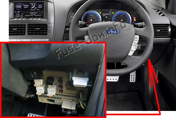
Fuse box diagram
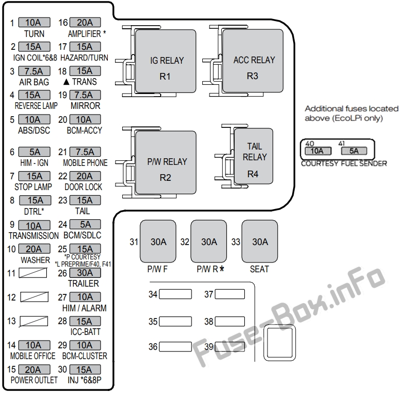
Assignment of the fuses and relays in the Passenger compartment
| № | Amps | Colour | Circuits Protected | Type |
|---|---|---|---|---|
| 1 | 10 | Red | Turn Signal Switch/Memory module (seat) | Ignition |
| 2 | 15 | Blue | Coil Driver (6 & 8 cylinder) | Ignition |
| 3 | 7.5 | Brown | Airbag | Ignition |
| 4 | 15 | Blue | Reverse Lights, Park Aid | Ignition |
| 5 | 10 | Red | DSC / ABS | Ignition |
| 6 | 5 | Tan | HIM | Ignition |
| 7 | 15 | Blue | Stop Lights, (PCM) | Ignition |
| 8 | 15 | Blue | Daytime Running Lights | Ignition |
| 9 | 10 | Red | Transmission | Ignition |
| 10 | 20 | Yellow | Washer Pump | Accessory |
| 11 | – | – | Not Used | – |
| 12 | – | – | Not Used | – |
| 13 | – | – | Not Used | – |
| 14 | 10 | Red | Mobile Phone | Accessory |
| 15 | 20 | Yellow | Power Outlet | Accessory |
| 16 | 20 | Yellow | Amplifier | Battery |
| 17 | 15 | Blue | Turn Signal / Hazard Lights | Battery |
| 18 | 15 | Blue | Transmission (I4) | Battery |
| 19 | 7.5 | Brown | Power Mirrors, Rear Demister Relay, Electrochromatic Mirror | Accessory |
| 20 | 10 | Red | Body Control Module | Accessory |
| 21 | 7.5 | Brown | Mobile Phone | Battery |
| 22 | 20 | Yellow | Door Locks | Battery |
| 23 | 15 | Blue | Tail/Park Lights, Switch Illumination, Display, Cluster, Interior Command Centre | Battery -Tail Relay |
| 24 | 5 | Tan | Body Control Module/SDLC | Battery |
| 25 | 15 | Blue | Petrol: Interior Lights, Solar Sensor, Gearshift (sports sequential), Rain Sensor
EcoLPi: BCM Battery Save Circuit (Preprime PCM, FEED Fuse 40 and 41) |
Battery/ Battery Saver |
| 26 | 30 | Green | Trailer | Battery |
| 27 | 10 | Red | HIM, Alarm, Diagnostic connector | Battery |
| 28 | 15 | Blue | Interior Command Centre, Display | Battery |
| 29 | 10 | Red | Instrument Cluster, Body Control Module | Ignition |
| 30 | 15 | Blue | Injectors (petrol) (6 & 8 cylinder) | Ignition |
| 31 | 30 | Pink | Front Power Windows | Battery, BCM Switched Window Relay |
| 32 | 30 | Pink | Rear Power Windows | |
| 33 | 30 | Pink | Power Seats | Battery |
| 34 | – | – | Not Used | – |
| 35 | – | – | Not Used | – |
| 36 | – | – | Not Used | – |
| 37 | – | – | Not Used | – |
| 38 | – | – | Not Used | – |
| 39 | – | – | Not Used | – |
| Additional Fuses – Located Above the Instrument Panel Fuse Box (EcoLPi only) | ||||
| 40 | 10 | Red | Interior Lights, Solar Sensor, Gearshift (sports sequential) – EcoLPi, Rain Sensor | Battery/ Battery Saver |
| 41 | 5 | Tan | Fuel Tank Level Sensor – EcoLPi | Battery/ Battery Saver |
| Relays | ||||
| R1 | – | White | Ignition | Ignition |
| R2 | – | White | Power Windows | BCM Switched |
| R3 | – | White | Accessory | Accessory |
| R4 | – | Black | Tail Lights | Light Switch |
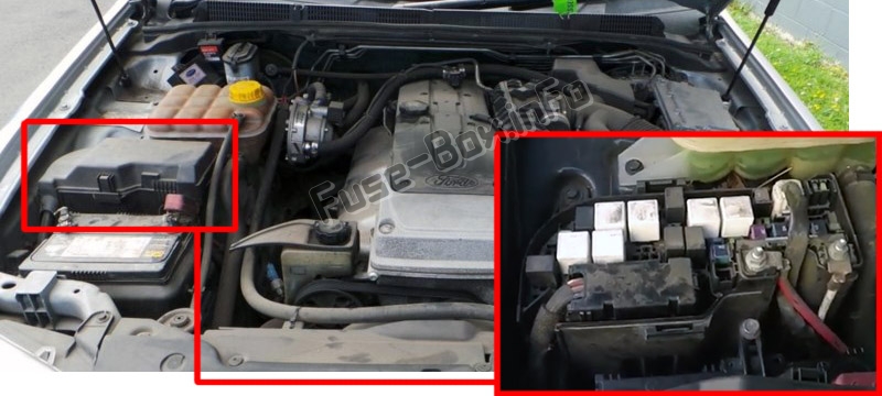
Engine compartment fuse box
Engine compartment fuse box
Fuse box location
Fuse box diagrams
6 Cylinder Petrol
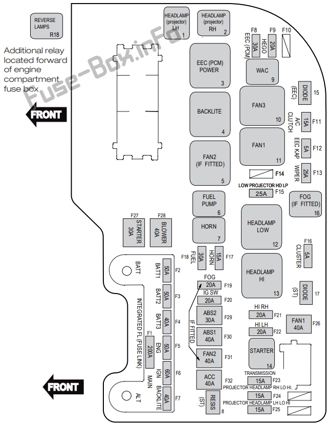
Assignment of the fuses and relays in the Engine compartment (6 Cylinder Petrol)
| № | Amps | Colour | Circuits Protected |
|---|---|---|---|
| F1 | 200 | Black – intergrated fuse link | Main |
| F2 | 50 | Black – intergrated fuse link | Batt 1 |
| F3 | 50 | Black – intergrated fuse link | Batt 2 |
| F4 | 40 | Black – intergrated fuse link | Batt 3 |
| F5 | 50 | Black – intergrated fuse link | Eng |
| F6 | 60 | Black – intergrated fuse link | Ignition |
| F7 | 40 | Black – intergrated fuse link | Backlight (Demister) |
| F8 | 30 | Green | EEC (PCM), IMCC, VCT |
| F9 | 20 | Yellow | Hego |
| F10 | – | – | Not Used |
| F11 | 15 | Blue | Air Conditioning Compressor |
| F12 | 5 | Tan | EEC (PCM) KAP |
| F13 | 25 | Natural | Wiper Front |
| F14 | – | – | – |
| F15 | 25 | Natural | Headlamps – Projector Lamps (Low) |
| F16 | 5 | Tan | Cluster |
| F17 | 15 | Blue | Horn |
| F18 | 30 | Green | Fuel |
| F19 | 20 | Yellow | Fog Lamp |
| F20 | 20 | Yellow | Ignition Switch, Alternator, Relay Coil, Fan, Ignition, Accessory |
| F21 | 20 | Yellow | Headlamp – High – Right |
| F22 | 20 | Yellow | Headlamp – High – Left |
| F23 | 15 | Blue | Transmission (Battery) |
| F24 | 15 | Blue | Headlamp – Low/High-Projector-RH |
| F25 | 15 | Blue | Headlamp – Low/High-Projector-LH |
| F26 | 40 | Green | Fan 1 |
| F27 | 30 | Pink | Starter |
| F28 | 40 | Green | Blower Fan – Climate Control |
| F29 | 30 | Pink | ABS 2 DSC2 (DSC VR) |
| F30 | 40 | Green | ABS1 DSC1 (DSC MR) |
| F31 | 40 | Green | Fan 2 |
| F32 | 40 | Green | Accessory |
| Relays | |||
| 1 | Black | Headlamp (Projector) – Keep on with High (LH) | |
| 2 | Black | Headlamp (Projector) – Keep on with High (RH) | |
| 3 | White | EEC (PCM) | |
| 4 | White | Backlight (Demister) | |
| 5 | Green | Fan 2 | |
| 6 | Black | Fuel | |
| 7 | Black | Horn | |
| 9 | Black | WAC (Air-Conditioning Compressor) | |
| 10 | White | Fan 3 | |
| 11 | White | Fan 1 | |
| 12 | White | Headlamp (Low) | |
| 13 | White | Headlamp (High) | |
| 14 | Black | Starter | |
| 16 | Black | Fog | |
| R18 | Black | Reverse Lamps (6-Speed Automatic Transmission) Located Forward of the Engine Compartment Fuse Box in the Engine Compartment |
|
| Diode | |||
| 15 | Black | EEC (PCM) | |
| 17 | Black | Starter | |
| Resistor | |||
| 8 | Green | Starter |
EcoLPi
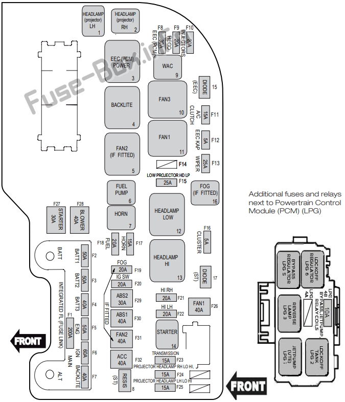
Assignment of the fuses and relays in the Engine compartment (EcoLPi)
| № | Amps | Colour | Circuits Protected |
|---|---|---|---|
| F1 | 200 | Black – integrated fuse link | Main |
| F2 | 50 | Black – integrated fuse link | Batt 1 |
| F3 | 50 | Black – integrated fuse link | Batt 2 |
| F4 | 40 | Black – integrated fuse link | Batt 3 |
| F5 | 50 | Black – integrated fuse link | Eng |
| F6 | 60 | Black – integrated fuse link | Ignition |
| F7 | 40 | Black – integrated fuse link | Backlight (Demister) |
| F8 | 30 | Green | EEC (PCM), LPG Relay Coils, LPG Bypass and Jet Pump Relay Feed, IMCC, VCT |
| F9 | 20 | Yellow | Hego |
| F10 | 20 | Yellow | Injector, LPG Module (LPG Engine) |
| F11 | 15 | Blue | Air-Conditioning Compressor |
| F12 | 5 | Tan | EEC (PCM) and LPG module KAP |
| F13 | 25 | Natural | Wiper Front |
| F14 | – | – | – |
| F15 | 25 | Natural | Headlamps – Projector Lamps (Low) |
| F16 | 5 | Tan | Cluster |
| F17 | 15 | Blue | Horn |
| F18 | 20 | Yellow | Fuel (LPG) |
| F19 | 20 | Yellow | Fog Lamp |
| F20 | 20 | Yellow | Ignition Switch, Alternator, Relay Coil, Fan, Ignition, Accessory |
| F21 | 20 | Yellow | Headlamp – High – Right |
| F22 | 20 | Yellow | Headlamp – High – Left |
| F23 | 15 | Blue | Transmission (Battery) |
| F24 | 15 | Blue | Headlamp – Low/High – Projector-RH |
| F25 | 15 | Blue | Headlamp – Low/High – Projector-LH |
| F26 | 40 | Green | Fan 1 |
| F27 | 30 | Pink | Starter |
| F28 | 40 | Green | Blower Fan – Climate Control |
| F29 | 30 | Pink | ABS 2 DSC2 (DSC VR) |
| F30 | 40 | Green | ABS1 DSC1 (DSC MR) |
| F31 | 40 | Green | Fan 2 |
| F32 | 40 | Green | Accessory |
| Relays | |||
| 1 | – | Black | Headlamp (Projector) – Keep on with High (LH) |
| 2 | – | Black | Headlamp (Projector) – Keep on with High (RH) |
| 3 | – | White | EEC (PCM) (LPG Engine) |
| 4 | – | White | Backlight (Demister) |
| 5 | – | Green | Fan 2 |
| 6 | – | Black | Fuel |
| 7 | – | Black | Horn |
| 9 | – | Black | WAC (Air-Conditioning Compressor) |
| 10 | – | White | Fan 3 |
| 11 | – | White | Fan 1 |
| 12 | – | White | Headlamp (Low) |
| 13 | – | White | Headlamp (High) |
| 14 | – | Black | Starter |
| 16 | – | Black | Fog |
| Diode | |||
| 15 | – | Black | EEC (PCM) |
| 17 | – | Black | Starter |
| Resistor | |||
| 8 | – | Green | Starter |
| Additional Fuses and Relays Located Beside the Powertrain Control Module (PCM) in the Engine Compartment | |||
| LPG1 | – | Black | Fuel Tank Jet Pump Solenoid (Ute Only) |
| LPG2 | – | Black | Fuel Tank Lock Off Solenoid |
| LPG3 | – | Black | Reverse Lamps |
| LPG 4A | – | – | Not Used |
| LPG 4B | 10 | Red | Relay Coils (Lockoff, Bypass and Jet Pump) Solenoids – Bypass and Jet Pump (LPG engine) |
| LPG5 | – | Black | Regulator Bypass Solenoid |
| LPG6 | – | Black | Regulator Lock Off Solenoid |
EcoBoost l4
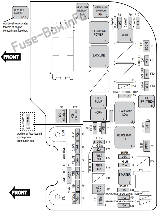
Assignment of the fuses and relays in the Engine compartment (EcoBoost I4)
| № | Amps | Colour | Circuits Protected |
|---|---|---|---|
| F1 | 200 | Black – integrated fuse link | Main |
| F2 | 50 | Black – integrated fuse link | Batt 1 |
| F3 | 50 | Black – integrated fuse link | Batt 2 |
| F4 | 40 | Black – integrated fuse link | Batt 3 |
| F5 | 50 | Black – integrated fuse link | Eng |
| F6 | 60 | Black – integrated fuse link | Ignition |
| F7 | 40 | Black – integrated fuse link | Backlight (Demister) |
| F8 | 30 | Green | VPWR 1 (ECM,EEC) Relay Coil (WAC and Fuel Pump) |
| F9 | 20 | Yellow | VPWR 2, HEGO, UEGO, Cannister Purge, Tl VCT (Intake and Exhaust) |
| F10 | 15 | Blue | VPWR 4 |
| F11 | 15 | Blue | Air-Conditioning Compressor |
| F12 | 5 | Tan | EEC (ECM) KAP |
| F13 | 25 | Natural | Wiper Front |
| F14 | – | – | – |
| F15 | 25 | Natural | Headlamps – Projector Lamps (Low) |
| F16 | 5 | Tan | Cluster |
| F17 | 15 | Blue | Horn |
| F18 | 30 | Green | Fuel |
| F19 | 20 | Yellow | Fog Lamp (if equipped) |
| F20 | 20 | Yellow | Ignition Switch, Alternator, Relay Coil, Fan, Ignition, Accessory |
| F21 | 20 | Yellow | Headlamp – High – Right |
| F22 | 20 | Yellow | Headlamp – High – Left |
| F23 | 15 | Blue | VPWR 3 – VRVS, ECBV (Vacuum Regulator Valve Solenoid, Electronic Compressor Bypass Valve) |
| F24 | 15 | Blue | Headlamp – Low/High – Projector-RH |
| F25 | 15 | Blue | Headlamp – Low/High – Projector-LH |
| F26 | – | – | Not Used |
| F27 | 30 | Pink | Starter |
| F28 | 40 | Green | Blower Fan – Climate Control |
| F29 | 30 | Pink | ABS 2 DSC2 (DSC VR) |
| F30 | 40 | Green | ABS1 DSC1 (DSC MR) |
| F31 | – | – | Not Used |
| F32 | 40 | Green | Accessory |
| F33 | 80 | – | Engine Cooling Fan (Midi Fuse) |
| Relay | |||
| 1 | – | Black | Headlamp (Projector) – Keep on with High (LH) |
| 2 | – | Black | Headlamp (Projector) – Keep on with High (RH) |
| 3 | – | White | EEC (ECM/PCM) |
| 4 | – | White | Backlight (Demister) |
| 5 | – | – | Not Used |
| 6 | – | Black | Fuel |
| 7 | – | Black | Horn |
| 9 | – | Black | WAC (Air-Conditioning Compressor) |
| 10 | – | – | Not Used |
| 11 | – | – | Not Used |
| 12 | – | White | Headlamp (Low) |
| 13 | – | White | Headlamp (High) |
| 14 | – | Black | Starter |
| 16 | – | Black | Fog |
| R18 | – | Black | Reverse Lamps (6-speed Automatic Transmission) |
| Diode | |||
| 15 | – | Black | EEC (ECM/PCM) |
| 17 | – | Black | Starter |
| Resistor | |||
| 8 | – | Green | Starter |
V8
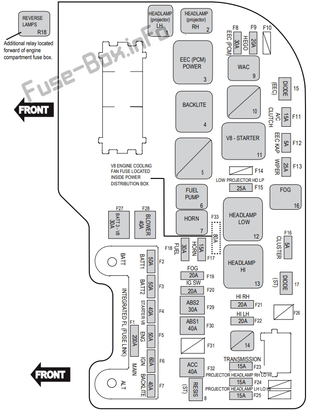
Assignment of the fuses and relays in the Engine compartment (V8)
| № | Amps | Colour | Circuits Protected |
|---|---|---|---|
| F1 | 200 | Black – intergrated fuse link | Main |
| F2 | 50 | Black – intergrated fuse link | Batt 1 |
| F3 | 50 | Black – intergrated fuse link | Batt 2 |
| F4 | 40 | Black – intergrated fuse link | Starter V8 Engine |
| F5 | 50 | Black – intergrated fuse link | Eng |
| F6 | 60 | Black – intergrated fuse link | Ignition |
| F7 | 40 | Black – intergrated fuse link | Backlight (Demister) |
| F8 | 30 | Green | EEC (PCM), IMCC, VCT |
| F9 | 20 | Yellow | Hego |
| F10 | – | – | Not Used |
| F11 | 15 | Blue | Air Conditioning Compressor |
| F12 | 5 | Tan | EEC (PCM) KAP |
| F13 | 25 | Natural | Wiper Front |
| F14 | – | – | Not Used |
| F15 | 25 | Natural | Headlamps – Projector Lamps (Low) |
| F16 | 5 | Tan | Cluster |
| F17 | 15 | Blue | Horn |
| F18 | 30 | Green | Fuel |
| F19 | 20 | Yellow | Fog Lamp |
| F20 | 20 | Yellow | Ignition Switch, Alternator, Relay Coil, Fan, Ignition, Accessory |
| F21 | 20 | Yellow | Headlamp – High – Right |
| F22 | 20 | Yellow | Headlamp – High – Left |
| F23 | 15 | Blue | Transmission (Battery) |
| F24 | 15 | Blue | Headlamp – Low/High-Projector-RH |
| F25 | 15 | Blue | Headlamp – Low/High-Projector-LH |
| F26 | – | – | – |
| F27 | 30 | Pink | Batt 3 V8 Engine |
| F28 | 40 | Green | Blower Fan – Climate Control |
| F29 | 30 | Pink | ABS 2 DSC2 (DSC VR) |
| F30 | 40 | Green | ABS 1 DSC1 (DSC MR) |
| F31 | – | – | – |
| F32 | 40 | Green | Accessory |
| F33 | 80 | – | Engine Cooling Fan V8 Engine |
| Relays | |||
| 1 | – | Black | Headlamp (Projector) – Keep on with High (LH) |
| 2 | – | Black | Headlamp (Projector) – Keep on with High (RH) |
| 3 | – | White | EEC (PCM) |
| 4 | – | White | Backlight (Demister) |
| 5 | – | – | – |
| 6 | – | Black | Fuel |
| 7 | – | Black | Horn |
| 9 | – | Black | WAC (Air-Conditioning Compressor) |
| 10 | – | – | – |
| 11 | – | White | Starter V8 Engine |
| 12 | – | White | Headlamp (Low) |
| 13 | – | White | Headlamp (High) |
| 14 | – | – | – |
| 16 | – | Black | Fog |
| R18 | – | Black | Reverse Lamps (6-Speed Automatic Transmission). Located Forward of the Engine Compartment Fuse Box in the Engine Compartment |
| Diode | |||
| 15 | – | Black | EEC (PCM) |
| 17 | – | Black | Starter |
| Resistor | |||
| 8 | – | Green | Starter |


