


Fuse Layout Ford Escape Hybrid 2011-2012
Contents

Cigar lighter (power outlet) fuses in the Ford Escape Hybrid are the fuse №40 (Front power point) in the Instrument panel fuse box, and fuse №3 (Rear power point) in the Engine compartment fuse box.
Table of Contents
Fuse box location
Fuse box location
Passenger compartment
The fuse panel is located on the right-hand side of the center console, by the instrument panel.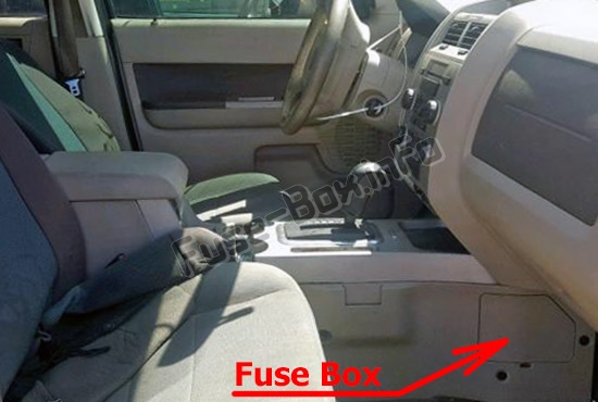
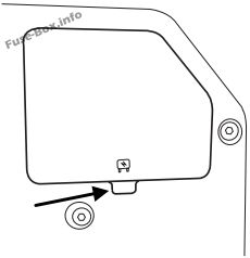
Remove the panel cover to access the fuse cover. Press the tabs on the top and bottom of the fuse cover to remove.
Engine compartment
The power distribution box is located in the engine compartment (left-side).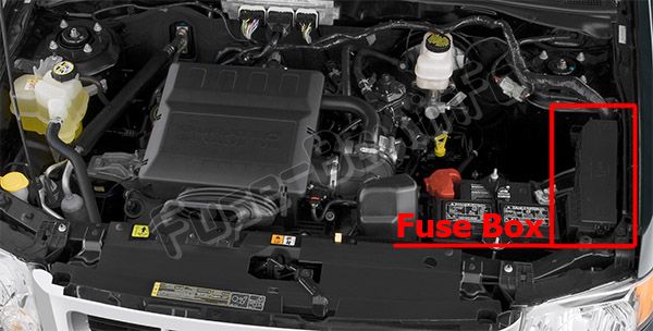
Auxiliary relay box
The relay box is located in the engine compartment on the radiator support bracket.
Fuse box diagrams
Fuse box diagrams
Passenger compartment
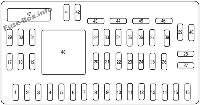
Assignment of the fuses in the Passenger compartment (2011, 2012)
| № | Amp Rating | Protected Circuits |
|---|---|---|
| 1 | 30A | 110V inverter |
| 2 | 15A | Brake on/off switch |
| 3 | 15A | SYNC® module |
| 4 | 30A | Moon roof |
| 5 | 10A | Brake-shift interlock (BSI), Passenger compartment fuse panel, Keypad illumination |
| 6 | 20A | Turn signals, Stop lamps |
| 7 | 10A | Low beam headlamps (left) |
| 8 | 10A | Low beam headlamps (right) |
| 9 | 15A | Interior lights |
| 10 | 15A | Backlighting |
| 11 | 10A | Four wheel drive |
| 12 | 7.5A | Power mirror switch |
| 13 | 5A | Not used (spare) |
| 14 | 10A | FCIM (radio buttons), Front display module, GPS module |
| 15 | 10A | Climate control |
| 16 | 15A | Not used (spare) |
| 17 | 20A | All lock motor feeds, Liftgate release, Liftglass release |
| 18 | 20A | Heated seat |
| 19 | 25A | Rear wiper |
| 20 | 15A | Datalink |
| 21 | 15A | Fog lamps |
| 22 | 15A | Park lamps |
| 23 | 15A | High beam headlamps |
| 24 | 20A | Horn relay |
| 25 | 10A | Demand lamps |
| 26 | 10A | Instrument panel cluster |
| 27 | 20A | Ignition switch |
| 28 | 5A | Radio |
| 29 | 5A | Instrument panel cluster |
| 30 | 5A | Not used (spare) |
| 31 | 10A | Restraints control module |
| 32 | 10A | Rear video camera module |
| 33 | 10A | Not used (spare) |
| 34 | 5A | Not used (spare) |
| 35 | 10A | Four wheel drive, Electronic power assist steering (EPAS), 110V inverter module, Park aid module, Active park assist module |
| 36 | 5A | Passive anti-theft system (PATS) transceiver |
| 37 | 10A | Not used (spare) |
| 38 | 20A | Subwoofer/Amp (premium radio) |
| 39 | 20A | Radio, Radio amplifier (navigation) |
| 40 | 20A | Front power point |
| 41 | 15A | Driver/passenger door lock switches, Auto dimming mirror, Compass, Ambient lighting, Moon roof, Camera display in mirror |
| 42 | 10A | Not used (spare) |
| 43 | 10A | Rear wiper logic, Heated seats relay, Instrument cluster |
| 44 | 10A | Not used (spare) |
| 45 | 5A | Front wiper logic, Blower motor relay |
| 46 | 7.5A | Occupant classification system (OCS), Passenger airbag deactivation indicator (PADI) |
| 47 | 30A Circuit Breaker | Power windows |
| 48 | — | Delayed accessory relay |
Engine compartment
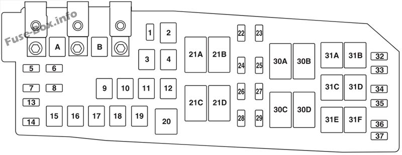
Assignment of the fuses in the Power distribution box (2011, 2012)
| № | Amp rating | Protected Circuits |
|---|---|---|
| A | 80A Midi | Power steering control module |
| B | 125A Midi | Passenger compartment fuse panel |
| 1 | 15 A* | Heated mirror |
| 2 | 30A** | Rear defroster |
| 3 | 20A** | Rear power point |
| 4 | 40A** | Electric vacuum pump |
| 5 | 10 A* | Powertrain control module (PCM) – keep alive power, PCM relay, Transmission control module, Canister vent |
| 6 | — | Not used |
| 7 | 15 A* | Liftgate latch |
| 8 | 5A* | Traction battery control module |
| 9 | 50A** | Brake control module |
| 10 | 30A** | Front wipers |
| 11 | — | Not used |
| 12 | 40A** | Blower motor |
| 13 | — | Not used |
| 14 | 10 A* | Heater/Coolant pump |
| 15 | 50A** | Traction battery control module CTBCM) |
| 16 | 40A** | Cooling fan 1 |
| 17 | 40A** | Cooling fan 2 |
| 18 | 50A** | Brake control module solenoid |
| 19 | 30A** | Power seats |
| 20 | — | Not used |
| 21A | — | Rear defroster relay |
| 21B | — | Ignition relay |
| 21C | — | Blower relay |
| 21D | — | PCM relay |
| 22 | 15 A* | Ignition coils |
| 23 | 15 A* | Fuel injectors |
| 24 | 10 A* | Transmission control module |
| 25 | 5A* | TBCM |
| 26 | 20 A* | Fuel pump, TBCM |
| 27 | 10 A* | PCM (general powertrain components malfunction indicator lamp), Heater pump relay, Motor electronics coolant pump relay, Electronic A/C compressor |
| 28 | 15 A* | Universal exhaust gas oxygen (UEGO) sensor, PCM – emission related powertrain components malfunction indicator lamp |
| 29 | 15 A* | PCM power |
| 30A | — | Cooling fan 1 relay |
| 30B | — | Electric vacuum pump mechanical relay |
| 30C | — | Cooling fan main relay |
| 30D | — | Cooling fan 2 relay |
| 31A | — | Reverse lamp relay |
| 31B | — | Not used |
| 31C | — | Heater pump relay |
| 31D | — | Coolant pump relay |
| 31E | — | Not used |
| 31F | — | Liftgate latch relay |
| 32 | — | Not used |
| 33 | — | PCM diode |
| 34 | — | Not used |
| 35 | 10 A* | Run/start, Reverse lamps, Rear defrost relay |
| 36 | — | Not used |
| * Mini fuse ** Cartridge fuse |
Auxiliary relay box
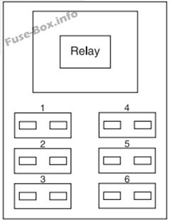
| № | Amp rating | Description |
|---|---|---|
| Relay | — | Electric vacuum pump (solid state) |
| 1 | — | Not used |
| 2 | — | Not used |
| 3 | — | Not used |
| 4 | 5A | Vacuum pump monitor |
| 5 | — | Not used |
| 6 | — | Not used |


